


Laurell Technologies
Quick Start WS-650 Series 10/2011 – 10070193.revL
All information contained in this manual is the property of Laurell Technologies Corporation® and is NOT to be edited, reproduced or
distributed without express written permission from a corporate officer.
- 1 -
QUICK START WS-650 LITE
INSTALLATION INSTRUCTIONS
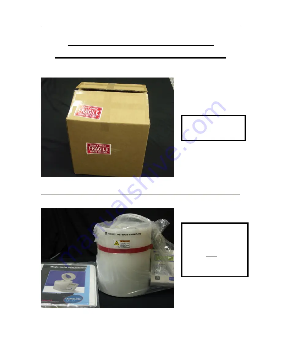
Open Boxes
Remove All
Contents
If any parts are
missing, contact the
factory immediately.
Claims for missing
parts must be made
within 30 days of
shipment.


