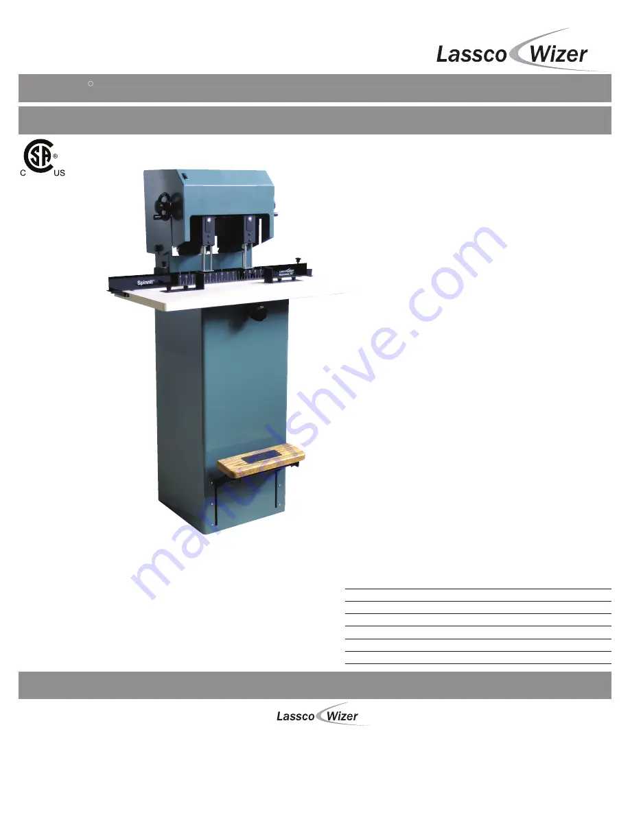
background image

USER’S MANUAL

Spinnit


FMM

 2


Manual Paper Drill

Before operating this equipment, please read these 

instructions completely and keep these operating 

instructions for future reference.

485 Hague Street, Rochester, NY  14606  U.S.A.

Tel:  585-436-1934

Fax:  585-464-8665

www.lasscowizer.com

[email protected]

Serial Number:

Date of Purchase:

Dealer:

Address:

Telephone Number:

-

R

Summary of Contents for Spinnit FMM-2

Page 1: ...lease read these instructions completely and keep these operating instructions for future reference 485 Hague Street Rochester NY 14606 U S A Tel 585 436 1934 Fax 585 464 8665 www lasscowizer com info lasscowizer com Serial Number Date of Purchase Dealer Address Telephone Number R ...

Page 2: ...ll Bits Adjusting the Table Height Adjusting the Back Gauge Assembly Adjusting the Distance Between Holes Adjusting the Stop Collars Multi hole Set up Traversing the Table Drilling Procedures Tips on Drilling 5 Maintenance 5 1 5 2 5 3 Page 14 Page 14 Page 16 Safety Annual Lubrication Inspecting the Flex Drive 6 Trouble Shooting Guide 6 1 Page 17 Determining the Cause and Correction to Certain Prob...

Page 3: ...ations or expose it to rain Keep work area well lighted THIS MACHINE IS DESIGNED FOR ONE PERSON OP ERATION Never operate the machine with more than one person KEEP CHILDREN AWAY All visitors should be kept a safe distance from the work area MAKE WORKSHOP KID PROOF with padlocks or master switches DON T FORCE MACHINE It will do the job better and safer at the rate for which it was designed USE RIGH...

Page 4: ...AVERTISSEMENT NE PAS EXPOSER À LA PLUIE ET NE PAS UTILISER DANS LES EMPLACEMENTS HUMIDES 2 Safety 2 2 Warning Labels Page 03 WARNING DO NOT EXPOSE TO RAIN OR USE IN DAMP LOCATIONS English French ...

Page 5: ...connect the equipment grounding conductor to a live terminal Check with a QUALIFIED ELECTRICIAN or service personnel if the grounding instruc tions are not completely understood or if in doubt as to whether the tool is properly grounded Use only 3 wire extension cords that have 3 prong grounding plugs and 3 pole receptacles that accept the machine s plug This machine is intended for use on a circu...

Page 6: ...Chip Clearer 1 FMM6 652A Chip Bag Assembly 1 MS 1 Drill Sharpener 1 FMM6 651A Master Chip Chute 1 This item may be installed EBM 32 Chuck Re lease Key 1 EBM 41 Sharpening Stone 1 SPIN EZE Drill Bit Lubricant 1 Hollow Drill Bits 2 these items may be installed FMM9 957A Spindle Rotation Tool 1 Short Set Screws 2 FM4 4007 Side Stop Screws 4 HEX 332 Hex Wrench 3 32 1 HEX 732 T Hex Wrench 7 32 T Style ...

Page 7: ...t the machine down in its desired location and determine if the machine is level making sure that it does NOT rock in any direc tion If it does determine which Leveling Feet need to be adjusted and whether they need to be adjusted up or down If adjustment is needed start by loosening the four 4 nuts which are accessed through the rear of the machine Next adjust the four 4 Leveling Feet by screwing...

Page 8: ...ar onto the bracket located on the top flat portion of the master chip chute as shown Please note that you must empty this bag as needed to avoid clogging Master Chip Chute Chip Bag Table Paper Side Stop Side Stop Screws 3 7 Electrical Instructions 3 7 1 3 7 2 Your FMM 2 comes with an electrical cord containing the plug to fit into a standard grounded 115V outlet This machine has a full load draw of...

Page 9: ...ion turn the Chuck Release Key 45 degrees The drill bit will slide out of the spindle It is recommended that you hold onto the drill bit so that it does not drop out of the spindle damaging the tip Place the hole guard back onto the chuck to protect debris from clogging the spindle Diagram 4 20 Chip Chute Chuck Hole Guard Drill Bit Chuck Release Key Tab CAUTION DRILL BITS MAY BE HOT AFTER USE ALLO...

Page 10: ...half turn loosening too much may cause the insert retainer screw to come out completely Retighten the insert retainer screw until it is snug but not tight this will al low you to raise or lower the chuck without too much play Hold onto the Spindle Rotation Tool to prevent the belts from turning Lower the height of the Chuck by turning it counter clockwise Raise the height of the Chuck by turning i...

Page 11: ... when it is positioned correctly If you are drilling into the Drill Strip Loosen the Lock Knob of the Vertical Stop Adjustment Assembly and rotate the large knob clockwise allowing the table to travel lower Tighten down the Lock Knob when it is positioned correctly 4 5 Adjusting the Back Gauge Assembly 4 5 1 4 5 2 4 5 3 4 5 4 4 5 5 Adjust the Back gauge so that it is the correct distance from the ...

Page 12: ...ough 4 7 5 Refer to diagram 4 110 Install the shorter Set Screws included with the machine into the Stop Collars Make sure all the Stop Collars are installed with the shorter Set Screws keeping them loose enough to allow the Stop Collars to slide into the desired positions Set the Stop Collars using the method explained in section 4 8 When the Collars are positioned as desired tighten down the sho...

Page 13: ...e next Stop Collar as shown 4 8 6 Due to the width of the Stop Collars the shortest travel between holes is 3 8 Almost any center to center distance can be drilled but requires variations of table travel and lateral head adjustments Ruler not provided Diagram 4 130 4 9 Traversing the Table 4 9 1 4 9 2 When all the Stop Collars are positioned as desired return the Table to its original position Whe...

Page 14: ...eplace worn out drill strips regularly to ensure proper drilling After all your adjustments are made as desired position the Table in its original position Set the product to be drilled on the table and make sure it is secure using the Paper Side Stops To drill step down on the Foot Treadle raising the Table up to meet the drill bits Using one consistent smooth stroke put pressure on the Treadle s...

Page 15: ...e the bars underneath the Slide as shown Re place the Table in the same manner as it was removed and check the Table traverse for free travel Refer to diagram 5 10 5 1 Safety ALWAYS DISCONNECT THE POWER BEFORE PERFORMING MAINTENANCE ON THIS MACHINE MAINTENANCE SHOULD ONLY BE PERFORMED BY A QUALIFIED TECHNICIAN KEEP HANDS CLEAR WHILE PERFORMING MAINTENANCE ON THIS MACHINE MOVING PARTS CAN CRUSH AND...

Page 16: ...rical wiring to the Switch on the shroud remove the shroud by lifting straight up to clear the drive mechanism making sure the Traverse Locks are disengaged Lubricate the two 2 Idler Pulleys with a good grade of grease A grease gun is required not included Rotate the belts by hand to check the Idler Pulleys for wear Some play between the Idler Pulley Bearings and the Idler Pins comply with origina...

Page 17: ...the out side edge of the Outside Pulley with the pulleys located one be hind the other Depress the belt halfway between the two pulleys and measure the distance between the straight edge and the belt depression The belts can be adjusted by loosening the Lock Nut on the Belt Adjustment Screw located on the front portion of the Flex Drive Pivot Assembly and turning the screw clockwise to tighten the...

Page 18: ...m lifts unevenly or is noisy Loose or missing pivot compo nents in the Treadle Pivot Assembly Tighten or replace as necessary Push Rods are bent Replace Bushings in the lift system are dry or worn Lubricate or replace Push Rods out of adjustment Adjust Push Rods to lift evenly Table traverse channel and or slide is dirty or needs lubrication Clean the channel and lubricate The Table is damaged Rep...

Page 19: ...bit s do not rotate when the motor is turned on A Drive Belt is broken on the Flexible Drive System Replace the broken belt See Maintenance A Drive Belt is loose on the Flexible Drive System Tighten the loose belt See Maintenance An Insert Retainer Screw is hitting the inside of the Chuck Housing Adjust the Chuck and tighten the Insert Retainer Screw The Hand Wheel Lock is tightend down in place L...

Page 20: ...st to a lower position which may require you to use new hollow drill bits The Chuck has been rotated while in the down position Push up on the Chuck and rotate slowly while holding the Spindle stationary until the Chuck returns into a locked position The Needle Bearings on the Idler Pulley s are not lubricated Lubricate the Needle Bearings as needed The Chuck adjustment is designed for a 1 4 total...

Page 21: ...7 Parts Diagrams 7 1 Side View Page 20 ...

Page 22: ...7 Parts Diagrams 7 2 Head Assembly Page 21 ...

Page 23: ...7 Parts Diagrams 7 3 Spindle and Chuck Assembly Page 22 ...

Page 24: ...7 Parts Diagrams 7 4 Rear View Page 23 ...

Page 25: ...N A FMH 5514 Chuck FM7 70A Back Gauge Assembly FM7 7005 Backgauge Knob FM7 7003 Clamp Bar FM4 4003 Side Iron FM4 4000 Table FM4 401A Pedestal Stop Assembly EBM 47 Stop Collar FM4 4014 Stop Collar Rod FM7 7002 Backgauge Clamping Bracket FM3 3007 Pin Housing FM3 304A Vertical Table Travel Stop Assembly FM2 2006 Push Rod FM 42 Short Clevis 50 31 Clevis Pin FM2 201A Push Rod Angle Assembly FM 37 Wear ...

Reviews: