

SLC 8000 Quick Start Guide
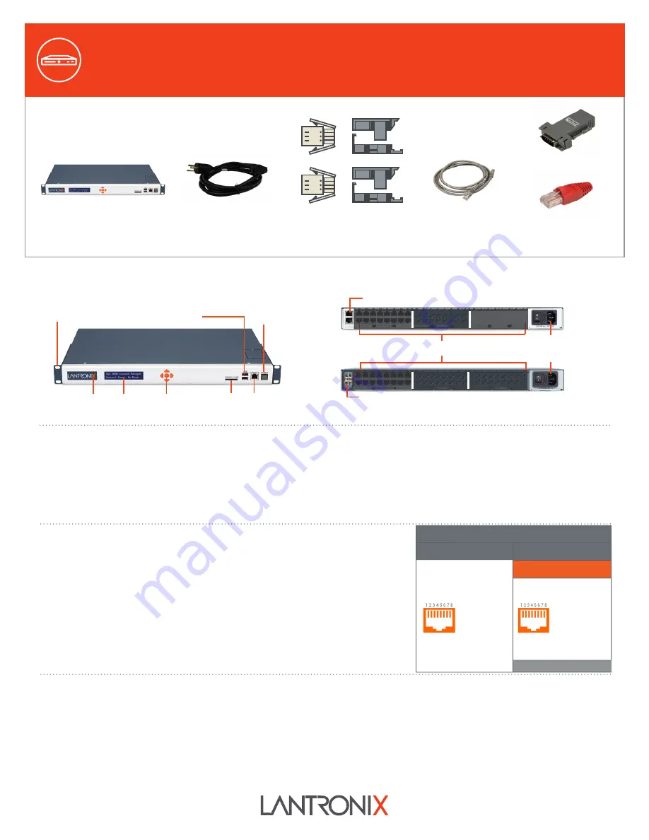
WHAT’S IN THE BOX
The front console port allows a dumb terminal or PC with terminal emulation software to locally
access management functions and connected devices.
The device ports allow simple and flexible connections to serial devices using adapters and a
standard CAT5 cable. Connect one end of the CAT5 cable to the device port and the other end to an
adapter that attaches to the serial console of the target system. For example, to connect a PC to the
console port of the SLC 8000, you only need the RJ45 to DB9F Adapter and a standard CAT5 cable
which is supplied with the unit.
The default communication parameters for the device ports and console ports are:
• 9600 baud • 1 stop bit • 8 data bits • No flow control • No parity
Note: SLC 8000 device ports are reversed by default, but are software configurable
.
1. Install the unit in a 19-inch rack.
Warning: Do not block the air vents on the sides of the unit. If mounted in an enclosed rack, it is recommended that the rack have a ventilation fan.
2. Connect the equipment to the numbered device ports on the back of the unit using the appropriate cables and adapters.
3. If you installed the internal modem, connect a RJ11 cable between the front panel modem port on the SLC 8000 to your phone line.
4. Connect the unit to the network using the upper network port. if your implementation is using an SFP fiber module then you will connect using fiber cables.
Please follow instructions from the SFP module vendor for the orientation of the cable.
5. Connect the power cord and apply power.
6. Wait about a minute and a half for the boot process to complete. When the boot process ends, the SLC model name and clock appear on the LCD. Detected
faults or process messages may also display.
Default Pin Assignments
Console Port (RS-232)
Device Ports (RS-232)
Reversed by Default
1. RTS (Out)
2. DTR (Out)
3. TX (Out)
4. GND
5. GND
6. RX (In)
7. DSR (In)
8. CTS (In)
1. CTS (In)
2. DSR (In)
3. RX (In)
4. GND
5. GND
6. TX (Out)
7. DTR (Out)
8. RTS (Out)
1. HARDWARE OVERVIEW
3. CONNECTING THE SLC 8000
4. HARDWARE INSTALLATION
SLC 8000
Console Manager
Front View
Back View (Model Dependent)
Front-mid-rear
Mounting Bracket
Indicator LED
LCD
Keypad
SD Card Console
Modem
(Optional)
Dual USB Ports
Device Ports (Modular)
Power Inlet
(Single/Dual AC or Dual DC)
10/100/1000 Mb Dual Network Ports
1Gb SFP Ports
1. Please carefully follow handling and installation guidelines provided by
the SFP transceiver module vendor.
2. Use care when inserting SFP transceiver module to the SFP port of
SLC 8000. Please be sure to understand orientation and how the latching
mechanism for the particular SFP transceiver module works.
3. Secure the latching mechanism (part of the SFP transceiver module
being inserted into the SFP port of SLC 8000).
Note:
Even though SFP transceiver module is a fiber interface, the SLC
8000 system interface will show SFP as Ethernet 1 and/or Ethernet 2.
Note:
Please contact Lantronix Technical Support to verify the compatibility of
a specific transceiver as not all are compatible.
2. INSTALLING SFP MODULES TO SLC 8000 SFP PORTS
The front LCD panel and keypad allow for quick and easy network configuration.
Software Reversible
Bay1
Bay2
Bay3
Bay1
Bay2
Bay3
Advanced Modular
Console Manager
RJ45 to DB9F Adapter
RJ45 Loopback Cable
For DC Supply Models:
DC Installation Kit only
083-152-R
For Ethernet Models:
RJ45 to RJ45 CAT5
Cable, 6.6 ft (2 m)
200.0062
For AC Supply Models:
AC Power Cord included only
500-041-R


