background image

MPM-1000A Operator Manual


1000-7075 Rev E


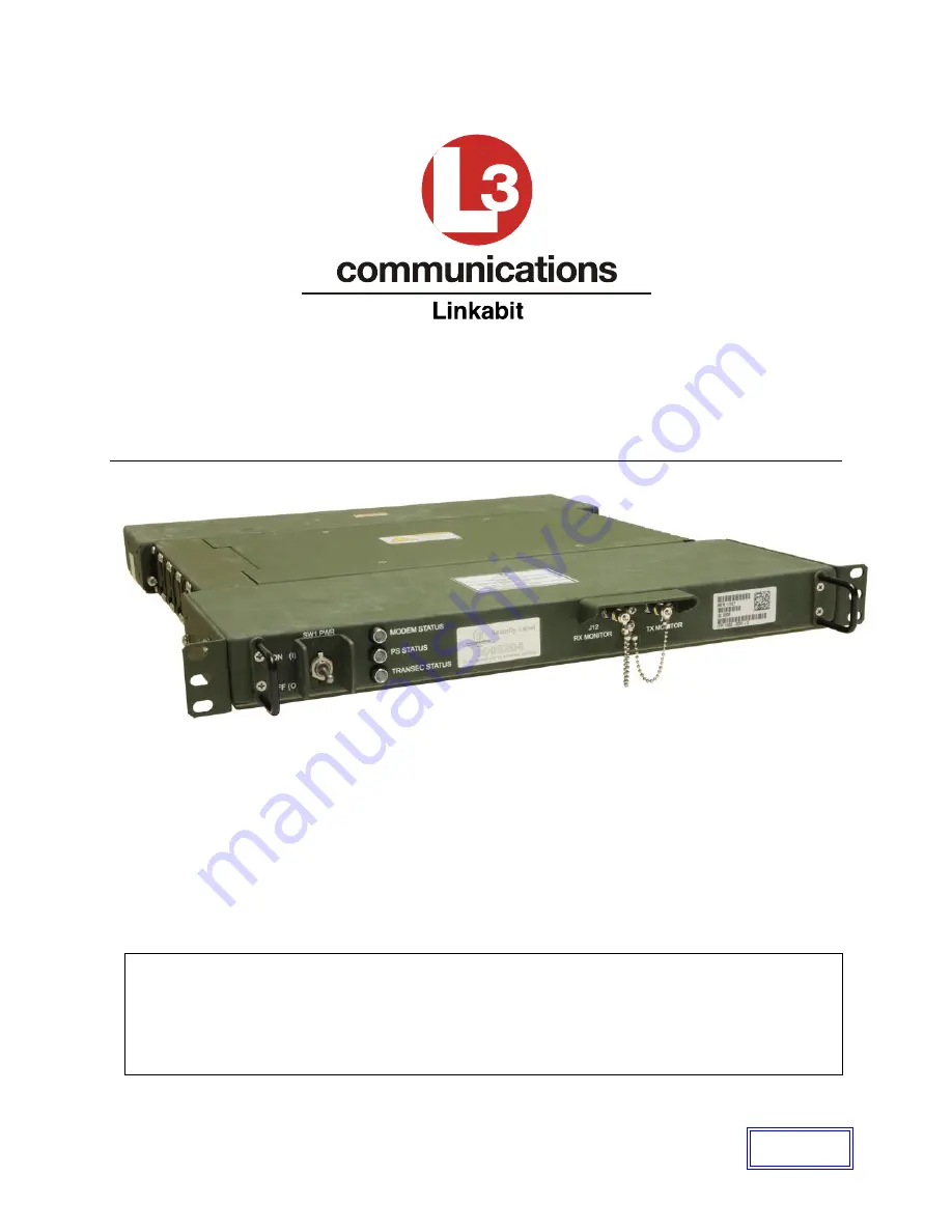
MPM-1000A RUGGEDIZED IP MODEM 

OPERATOR MANUAL 


3033 Science Park Road 
San Diego, CA 92121 
1-800-331-9401 
 
29 April 2011 


WARNING:  This document contains technical data whose export is restricted by the Arms Export Control Act (Title 22, U.S.C. 
Sec 2751, et seq.) or the Export Administration Act of 1979, as amended (Title 50, U.S.C., app. 2401 et seq.) Violators of 
these export laws are subject to severe criminal penalties. 

 
This information in document form (or any other medium), including any attachments and exhibits hereto, may not be 
exported, released or disclosed to foreign persons whether here in the United States or abroad without first obtaining the 
proper export authority. Recipient shall include this notice with any reproduced portion of this document.  


DOCUMENT 

CONTROL


Summary of Contents for MPM-1000A

Page 1: ...Export Administration Act of 1979 as amended Title 50 U S C app 2401 et seq Violators of these export laws are subject to severe criminal penalties This information in document form or any other medium including any attachments and exhibits hereto may not be exported released or disclosed to foreign persons whether here in the United States or abroad without first obtaining the proper export autho...

Page 2: ... 107183 22 MAR010 AP DL MB KH PR C Updated to match MIL STD for manuals ECN 107553 03 AUG 2010 BL AP TB DL KA PR D Added new functions Multiple Mode Configuration Multicast Terminal Calibration RX Attenuator Description ECN 107755 01 OCT 2010 BL AP DL KA BL AP TB DL KA PR PR E Update Table 14 1 Updated section 14 3 2 Tables Updated Pages 15 1 and 15 2 ECN 108567 Upt 29 APR 2011 BL AP TB RR DR ...

Page 3: ...lation 4 1 4 3 HCI Software Installation Procedure 4 2 4 4 Configure PC IP Address 4 2 4 5 Human Computer Interface 4 3 4 6 Human Computer Interface Familiarization 4 4 4 7 Overall Status Screen 4 4 4 8 Software Version Screen 4 5 4 9 Modem CDU Port IP Address 4 6 4 10 Installation and Update Procedure Modem 4 8 5 SOFTWARE MENU OVERVIEW 5 1 5 1 Launch Modem HCI 5 1 5 2 SNMP Dialog 5 2 5 3 Modes of...

Page 4: ...nd Network Members 8 1 8 1 2 Network Controller Capable 8 2 8 2 NCW Signals 8 3 8 2 1 Reference Forward Orderwire RFOW 8 3 8 2 2 Return Orderwire ROW 8 3 8 2 3 Data Communications Burst DCOM 8 4 8 2 4 NCW Traffic Example 8 4 8 3 Network Initiation 8 5 8 4 Network Operation 8 5 8 5 Network Operation with Wideband Global Satellite 8 7 8 6 Setting the Terminal for NCW Mode as Network Controller 8 9 8...

Page 5: ... List 10 8 10 7 Group Status 10 9 11 SCPC NETWORK OPERATIONS 11 1 11 1 Selecting MIL STD 188 165A SCPC Mode 11 1 12 PREVENTIVE MAINTENANCE CHECKS AND SERVICES PMCS 12 1 12 1 Introduction 12 1 12 2 Inspection 12 1 12 3 Cleaning 12 2 12 4 Description of PMCS Table Columns 12 2 13 TROUBLESHOOTING 13 1 13 1 Introduction 13 1 13 2 General Troubleshooting Guidelines 13 1 13 3 Modem BIT and Status Troubl...

Page 6: ...mat 15 5 15 8 Recovery 15 5 15 9 Over The Air Zeroize OTAZ 15 5 15 10 Recovery Protocol Actions at the Initiating Terminal 15 6 15 11 Recovery Protocol Actions at the Network Controller 15 6 15 12 Alternate Recovery Procedures 15 7 15 13 Key Usage 15 7 15 14 Network Initiation 15 8 15 15 TRANSEC Key Rollover 15 8 16 APPENDIX B RX ATTENUATOR DESCRIPTION 16 1 17 GLOSSARY OF ABBREVIATIONS AND ACRONYM...

Page 7: ...ver Successful Screen 4 12 Figure 4 18 Connection Lost Status Screen 4 12 Figure 5 1 HCI Desktop Icon 5 1 Figure 5 2 Network Screen at Startup 5 1 Figure 5 3 SNMP Mode Change 5 2 Figure 5 4 SNMP Configuration Dialog 5 2 Figure 5 5 Connection Lost Status Screen 5 3 Figure 5 6 Select Mode 5 4 Figure 5 7 Configure Menu 5 4 Figure 5 8 Select Mode Screen 5 5 Figure 5 9 Network Main Screen 5 5 Figure 5 ...

Page 8: ...TERM CAL ON Status box 6 22 Figure 6 27 Terminal Calibration Screen 6 22 Figure 6 28 Calibration File Screen 6 23 Figure 6 29 File Validation Success 6 23 Figure 6 30 Losses Screen 6 24 Figure 6 31 Terminal Losses File Screen 6 25 Figure 6 32 File Validation Successful 6 25 Figure 6 33 Configure Menu 6 25 Figure 6 34 Terminal Gains File Screen 6 26 Figure 6 35 Manual Entry Screen 6 27 Figure 6 36 ...

Page 9: ... 9 4 NCW Message Tab 9 5 Figure 9 5 NCW Statistics Tab 9 7 Figure 9 6 NCW RX Burst Tab 9 9 Figure 9 7 NCW RX Comm Tab 9 11 Figure 9 8 NCW TX Comm Tab 9 13 Figure 9 9 NCW TX Queue Tab 9 14 Figure 9 10 NCW Parameters Tab 9 15 Figure 9 11 NCW Advanced Tab 9 17 Figure 9 12 NCW QOS Tab 9 18 Figure 10 1 R2CP Config Tab 10 1 Figure 10 2 R2CP Sessions Tab 10 4 Figure 10 3 R2CP Sessions Tab Operational Sta...

Page 10: ...MPM 1000A Operator Manual 1000 7075 Rev E x Figure 15 2 SSH Network Connection 15 3 ...

Page 11: ...e Tab 8 14 Table 8 3 NCW Statistics Tab 8 16 Table 8 4 NCW BW EIRP Tab 8 18 Table 8 5 NCW Path Loss Tab 8 20 Table 8 6 NCW RX Burst Tab 8 22 Table 8 7 NCW RX Comm Tab 8 23 Table 8 8 NCW TX Comm Tab 8 25 Table 8 9 NCW TX Queue Tab 8 26 Table 8 10 NCW Link Budget Tab 8 27 Table 8 11 NCW Setup Parameters Tab 8 29 Table 8 12 NCW Setup Advanced Tab 8 30 Table 8 13 NCW QOS Tab 8 32 Table 8 14 NCW PSD Ta...

Page 12: ...able 14 4 TX Intermediate Frequecy Output Interface 14 7 Table 14 5 TX Intermediate Frequecy Monitor Interface 14 7 Table 14 6 Modem RX Intermediate Frequency Input Interface 14 8 Table 14 7 RX Intermaediate Frequency Monitor Interface 14 8 Table 14 8 Control Monitor and Alarm ETHERNET Interface 14 9 Table 14 9 Data ETHERNET Interface 14 9 Table 14 10 SCPC Baseband Interface 14 10 Table 14 11 Secu...

Page 13: ...ents or make adjustments inside the equipment with the equipment s power supply turned on Under certain conditions potential danger may exist when power control is in the off position due to charges briefly retained by internal power supply capacitors To avoid injuries always remove power from the main power panel at the installation site apply power to the unit to discharge the capacitors and the...

Page 14: ...ed in the text use as described in this Operator Manual which should not result in any immediate health concerns Consult the local Bioenvironmental Engineer for specific protective equipment and ventilation requirements USE SAFETY APPROVED EQUIPMENT When cleaners and primers are being applied approved explosion proof lights blowers and other equipment shall be used Ensure that firefighting equipme...

Page 15: ...tion with incorrect settings may cause severe damage to the Antenna Please ensure you are familiar with all parameters that may be entered and the impact they have on the Transmit Chain Gain Factor TCGF Please check your Antenna manufacturer specifications prior to changing any of the following settings If you increase the Modem TX Power Setting above the Antenna s Maximum power rating the pop up ...

Page 16: ...part of a Terminal system 7 Transmission Security This section discusses the security methods provided to protect and encrypt Modem communications 8 Network Control Operations This section provides a theory of operations for networks and details the procedures required to operate the Modem as a Network Controller NC along with the unique features available in that mode 9 Network Member Operations ...

Page 17: ...itles and document titles are in italics Keyboard commands are capitalized and bracketed around the text all text to include brackets bold ex Press the ENTER key Press the ESC key The following are Interactive Example Conventions used in this manual Terminal sessions and system messages are in Courier New font Information that the user is required to enter is in boldface Courier New font User defi...

Page 18: ...porting mistakes or suggesting improvements or recommendations via postal mail please direct all inquiries as follows TO MPM 1000 Modem Product Manager L 3 Communications Linkabit 3033 Science Park Rd TPII San Diego CA 92121 If reporting mistakes or suggesting improvements or recommendations via electronic mail please direct all inquiries to the Linkabit Product Services Help Desk at the following...

Page 19: ...y between a local LAN and a remote LAN using standard 1000 Base T Ethernet interfaces NCW mode also supports a digital voice baseband interface enabling simultaneous bi directional transfer of digitized voice data When used in the NCW mode the Modem provides full duplex transmission of Internet Protocol IP data between local and remote LANs via satellite through its Ethernet data port using Multip...

Page 20: ...hniques and modulation schemes within the Modem that are described throughout this manual When operating in the NCW Mode the Modem is capable of operating as a Network Controller NC or an Alternate Network Controller ANC as well as a Network Member NM With its ability to be customized and configured for different network modes the Modem is designed to be a highly flexible Terminal solution when us...

Page 21: ... BASE T Ethernet port CD ROM drive 1 4 Software Version Information This document covers procedures and requirements for the following software versions Modem software version 8 03 HCI version 5 1 7 42 This document may be superseded by later versions of the HCI which may cause visual changes to the applications window content If you have later versions of the HCI refer to release notes or accompa...

Page 22: ...aseband Voice VOW 1 RS 422 RS 423 Sync Full Duplex 16 kbps Burst Data Rate 32 kbps 4 096 Mbps per carrier Turbo Coding SCCC Interleaver Block Length 1280 Modulation Formats BPSK Rate Coding OQPSK Rate and Coding 8 ARY PSK R Coding Direct Sequence Spreading 1 16 0 to 12 dB Voice Orderwire Carrier 1 Tx 1 Rx MF TDMA Carriers 2 Tx 1 if VOW used 4 Rx 3 if VOW used Encryption AES 256 CBC TRANSEC Control...

Page 23: ...powering the Ruggedized Modem 3 1 Panel Indicators The front panel of the Ruggedized Modem contains one 1 power switch three 3 Light Emitting Diode LED Modem status indicators and two 2 L Band Monitor ports The rear panel of the Modem contains the majority of the Input Output I O connections for the device 7 8 9 10 11 12 13 14 15 16 17 18 19 1 2 3 4 5 6 Figure 3 1 Modem Panels ...

Page 24: ...ol the Modem in the SCPC mode 11 J5 Baseband Data Port Provides bi directional data transfer between the Modem and external Baseband equipment when operation in the SCPC mode 12 J6 Terminal Devices Supports asynchronous exchange of control and status information between the Modem and external Terminal equipment The Frame Strobe signal on this connector is utilized by the Modem in stacking operatio...

Page 25: ...igure 4 1 c Connect Power Cable to Modem d Turn on PC e Turn on Modem and allow the Modem to fully boot This can take up to four 4 minutes The Modem is operational when the front panel status LED illuminates Green 192 0 1 X Control Data PC CDU 192 0 1 2 Control PC Figure 4 1 LAN Connection to PC 4 2 Prepare PC for Software Installation A PC is required for hosting the Modem HCI program The system ...

Page 26: ... to the C drive and create a new folder titled IPModemHCI e Copy the new HCI folder from the CD to the IPModemHCI folder on the C drive f Open the IPModemHCI directory on the C drive and then open the directory with the latest version g Double click the IPModemHCISetup msi file to execute Follow the instructions to install the new version of the HCI software An Icon will be placed on the desktop a...

Page 27: ...The primary interface for Monitor and Control of the Modem is an HCI GUI running on a PC that is attached via Ethernet to the Modem s CDU port Modem operation is organized into four 4 modes of operation MIL STD 188 164A Waveform In this mode the Modem is configured as an SCPC Modem conforming to MIL STD 188 165A See Section 10 for more detailed operation NCW without SVOW This is the most common mo...

Page 28: ...ganized into three 3 distinct segments that provide information and control functions dependent on the mode and status of the system 4 7 Overall Status Screen The Overall Status Screen Segment is the top border for all screens It provides a summary status of the Modem and allows quick access to the most commonly used screens It also provides access to the Alarm Acknowledge and Emergency Zeroize co...

Page 29: ...e is synchronized to the local PC or Network Time Protocol NTP server connected to the NC The NC in turn provides this timing to the rest of the NMs in the Reference Forward Orderwire RFOW burst so that all network nodes reflect the same time When a Modem is NOT CONNECTED to an NCW network the timing source i e single PC or NTP server can be changed to update the time on the HCI When a Modem IS CO...

Page 30: ...version of the HCI and the loaded configuration file if any 4 9 Modem CDU Port IP Address The IP address for the CDU port must be set to allow communication with the Modem The default shipped address of the modem CDU port IP address is 192 0 1 2 This may be changed if required To change this IP address you must set the IP address in the IPv4 Address portion of the HCI COMM Address Screen A change ...

Page 31: ...em s CDU Port See Figure 4 8 c Click Save d Cycle power to reboot the Modem If the CDU port address is changed and the PC can no longer talk to the CDU port the Modem may be rendered inoperable Contact your System Administrator to make any changes to this window Figure 4 8 HCI to Modem Address Screen CAUTION ...

Page 32: ...he PC The software may be copied from a CD ROM a Universal Serial Bus USB flash memory device or other storage media 1 Insert the memory device that contains the new version into the PC 2 Use Windows Explorer to navigate to the removable device normally the D or E drive 3 Select the new version of the IP_Modem_Terminal 4 Copy the new version to the IP_Modem_Terminal folder on the C drive 5 Shut do...

Page 33: ...d with step 4 4 From the Menu bar select Software Download Rollover to display the Software Download window See Figure 4 11 Figure 4 11 Software Menu 5 On the Software Download screen click the File button and browse to the new version that was placed on the C drive in step a See Figure 4 12 NOTE The software download screen shown is when the Modem is in a multiple Modem configuration For more inf...

Page 34: ... 10 Figure 4 12 Software Download Showing Selected File Figure 4 13 Open Screen to Select Software to Download 6 Highlight the desired file and click Open The pop up window will close See Figure 4 13 7 Click Start Download to launch the process ...

Page 35: ... data field indicates Verification OK click the Software Rollover button Figure 4 15 Refer to Table 4 2 Software Download and Rollover for data descriptions for this window Figure 4 15 Software Download Verification Screen 9 When the Confirm window appears click OK The rollover may take approximately 20 minutes See Figure 4 16 ...

Page 36: ...his is normal when the Modem is rebooting See Figure 4 18 Figure 4 18 Connection Lost Status Screen Your Modem is now updated and ready to connect to an Antenna Table 4 1 Software Download and Rollover Screen Software Download Functions File button Bring up a File Selection dialog for choosing the file to download Start Download button Only active if a file has been selected When clicked initiates...

Page 37: ...HCI This section will familiarize you with Modem capabilities and navigation 5 1 Launch Modem HCI After installing the Modem software double click the IPModemHCI icon located on the PC desktop See Figure 5 1 Figure 5 1 HCI Desktop Icon If the Modem is in NCW mode the following network screen will then display See Figure 5 2 Figure 5 2 Network Screen at Startup ...

Page 38: ...Figure 5 4 SNMP Configuration Dialog with the current mode set to V2 In SNMPV2 operation you may change the community string to match that of the Modem In SNMPV3 operation you may change the type of Authentication and enter the credentials required to communicate at the level required Selecting Yes on this screen will say that the HCI must be restarted to change SNMP Mode settings and that you wan...

Page 39: ...ng to MIL STD 188 165A See section 10 for more detailed operation NCW without SVOW This is the most common mode of operation and places the Modem in the NCW operation mode To configure the Modem in this mode terminal parameters are entered See Section 6 and Network Member Parameters are configured See Section 9 If the Modem is designated as a Network Controller then Network Parameters are also con...

Page 40: ...00 7075 Rev E 5 4 Figure 5 6 Select Mode 5 4 Selecting Maintenance Mode a Select Configure Mode from the pull down menu to launch the Select Mode screen See Figure 5 7 Figure 5 7 Configure Menu b Select Maintenance See Figure 5 8 ...

Page 41: ...s finished initializing the Maintenance Mode the system will be in the Maintenance 5 5 System Shutdown NOTE Exiting the HCI does not terminate Modem operation a To stop the Modem in NCW mode click on Network Terminate Figure 5 9 Network Main Screen b To stop the Modem in SCPC mode select TX Power Enable No ...

Page 42: ... to run 5 6 File Pull Down Menu An enhanced File pull down menu is available while in Maintenance Mode The enhancements to this pull down menu are Save Config Save Config As and Restore Config See Figure 5 11 During any other Mode only the Exit menu option is available a Select File to open the drop down menu b Select appropriate command you wish to complete Refer to Table 5 1 File Configuration f...

Page 43: ...cation only the MPM 1000 Modem will continue to run 5 7 Save Save As Configuration The Save Configuration dialog appears when you request to save a configuration file for the Modem Refer to Table 5 2 Save Configuration for data descriptions for this window Figure 5 12 Save Configuration a Type in a description in the Description Field b Select the items that you wish to save in this configuration ...

Page 44: ...eters will be saved if selected MIL STD 188 165A Parameters Current 165A parameters will be saved if selected Figure 5 13 Save As Dialog 5 8 Restore Configuration The Restore Configuration dialog allows you to select a previously stored configuration and restore the Modem to that configuration Specific restore options are selectable along with Modem mode after restoration a Select the appropriate ...

Page 45: ...tings to ensure that the correct configuration file has been selected d In the Modem Mode After Restore field select which mode the Modem will operate in after the restore e Select Restore Refer to Table 5 3 Restore Configuration for data descriptions for this window Figure 5 15 Restore Configuration ...

Page 46: ...itude Longitude will be restored Terminal Parameters If selected the saved Terminal parameters will be restored Satellite Parameters If selected the saved Satellite parameters will be restored NCW Parameters If selected the saved NCW parameters will be restored Data Port IP Address If selected the Data Port IP Address will be overwritten Default is un selected MIL STD 188 165A Parameters If select...

Page 47: ...his menu links to pages and dialogs used to setup and operate the Modem Some of the menu choices are on the Overall Status Screen as tabs a Select Configure b Select appropriate item you wish to activate See Figure 5 17 Refer to Table 5 4 Configure Menu for data descriptions for this window Figure 5 17 Configure Menu ...

Page 48: ...reen From this screen you can configure various satellite terminal parameters such as Location Block Up Down Converter frequencies and antenna settings Modem The Modem item opens the Modem screen From this screen you can configure various Modem parameters In a multiple MPM configuration this screen will provide access to all modems in the configuration Selection of this item brings up the Select m...

Page 49: ...or Manual 1000 7075 Rev E 5 13 5 10 Monitor Pull down Menu This menu provides links to the Alarms and Events screens a Select Monitor See Figure 5 18 b Select appropriate item you wish to view Figure 5 18 Monitor Menu ...

Page 50: ...reen This page controls Terminal specific parameters that are set on the initial installation Once set these parameters generally do not change a Select Configure System the Configure System screen will appear See Figure 6 1 Figure 6 1 Configure Menu Refer to Table 6 1 Configure System Configuration Screen for data descriptions for this window ...

Page 51: ...Latitude 2 Enter Satellite dish s Longitude 3 Enter Satellite dish s Altitude 4 Select Apply c Edit Block Converter 1 Edit BUC LO Frequency 2 Edit LNA LNB LO Frequency 3 Select Apply d Edit Rx Attenuator 1 Set Rx Noise Temperature 2 Set Rx Gain 3 Select Apply e Edit Internal Modem Temperature a Set High Thresh b Set Low Thresh c Select Apply ...

Page 52: ...A The Modem software uses the block converter frequencies and the satellite uplink and downlink frequencies to compute and set the Modem transmit and receive frequencies Antenna Allows you to select antenna type Two antenna types are available Circular Aperture and FSS 4180 LP If Circular Aperture type is selected then Aperture size in inch meters is available to you You can use the up down arrows...

Page 53: ...use damage to equipment that is attached to the receive and or transmit port 6 3 Satellite Setup After changing a satellite configuration item please wait for at least 15 seconds before turning off the Modem power This allows the Modem software time to write the updated configuration to its persistent storage 6 3 1 Satellite List Screen This list of satellites is the entry point to updating satell...

Page 54: ...ected center frequency PN Select Pseudo random number identifier for spread spectrum operation Beam Selecting Beam will open a dialog box to edit add or delete a selected beam B W Segments Selection B W Segments will open a dialog box to edit add or delete a selected B W Segment 6 3 2 Beams List You use this dialog to select a beam to edit or to add a beam to this Satellite Click on the Beam butto...

Page 55: ...p the Beam Edit dialog Delete button Deletes the selected beam 6 3 3 Beam Edit Dialog You use this dialog to edit the selected satellite beams See Figure 6 6 Refer to Table 6 5 Edit Beam Dialog for data descriptions for this window Figure 6 6 Edit Beam Dialog Note Uplink center frequency downlink center frequency and bandwidth are used to validate bandwidth segment entries on the bandwidth segment...

Page 56: ...urn Orderwire CROW slots to be scheduled in this beam Spreading Spread factor to use for the CROWs in this beam Most Disadvantaged Network Terminal in this beam EIRP and G T of the most disadvantaged terminal expected to be participating as a network member in this beam G T G T of the most disadvantaged terminal in this beam EIRP EIRP of the most disadvantaged terminal in this beam Contour Offsets...

Page 57: ...dwidth Segment Edit Dialog You use this dialog to edit a selected bandwidth segment See Figure 6 8 Note Uplink center frequency and downlink center frequency are required fields The Ruggedized Modem software uses these frequencies along with the block converter frequencies to compute transmit and receive frequencies Modem Frequency Satellite Frequency Block Converter Frequency Refer to Table 6 7 E...

Page 58: ...MPM 1000A Operator Manual 1000 7075 Rev D 6 9 Refer to Table 6 7 Edit Bandwidth Segment for data descriptions for this window Figure 6 9 Edit Bandwidth Segment Dialog using Saturated Flux Density ...

Page 59: ...erminal gain and power that should be preferentially scheduled into this bandwidth segment Terminal minimum EIRP Min EIRP Terminal minimum G T Min G T Terminal maximum EIRP Max EIRP Terminal maximum G T Max G T Gain of this Bandwidth Segment Transfer Gain Total transfer gain for this bandwidth segment Saturated Flux Density This field is measured in dBW m 2 Input Output Backoff This field is measu...

Page 60: ... CDU ports For more information to connecting the stack on the rear of the Modem refer to section 14 2 Modem Stacking Installation NOTE The IP addresses are for illustration purposes only These settings are user defined Figure 6 10 Modem Stack 6 4 1 Configuring Master Modem This procedure assumes that all modems are set to factory defaults with the IP address set to 192 0 1 2 CDU Network Switch Sl...

Page 61: ...em a Set the Modem to Maintenance Mode if in Maintenance Mode skip to Section 6 4 3 b Select Configure Mode See Figure 6 11 Figure 6 11 Configure File Menu c Select Maintenance and then click OK See Figure 6 12 Figure 6 12 Select Mode Screen d The Modem will change modes Wait until the new mode has completed initializing to proceed 6 4 3 Set the CDU and Data Ports This will set the CDU and Data Po...

Page 62: ... Address in CDU NEW to the desired network configurations See Figure 6 14 Copy the CDU IP Address on a paper for future reference If the CDU port address is changed and the PC can no longer talk to the CDU port the Modem may be rendered inoperable c Set the CDU IP Address and the Data IP Address to the desired network configuration See Figure 6 14 CAUTION ...

Page 63: ...will be the Master Modem of the stack 6 4 4 Configure Slave Modem a Connect the Slave Modem to the network switch b Turn on the Slave Modem wait until Modem Status LED has turned green c Set Slave Modem in Maintenance Mode See Section 6 4 2 d Select Modem Tab See Figure 6 16 Configure Modem Screen e Set Frequency Reference to 10MHz External The System will show alarms and HW status box will go red...

Page 64: ...v D 6 15 Figure 6 16 Configure Modem Screen f Turn off Slave Modem g Repeat steps a through f for each additional slave h Turn on the Master Modem and wait for the Modem Status LED turns green i Select Configure Modem Stack See Figure 6 17 ...

Page 65: ...Master Once the Master Modem has been highlighted the Configure SLAVE Button will be active See Figure 6 18 Refer to Table 6 8 Multi Modem Status Screen for data descriptions for this window Figure 6 18 Multi Modem Configuration Screen k Select Configure SLAVE A pop up box will appear See Figure 6 19 ...

Page 66: ...control the stack n Set the SLAVE CDU Port IP This will change the CDU IP address of the slave o Set the Modem Name This field will give the Slave Modem a name This is important when dealing with more than one 1 slave p Select OK q Power Off the slave r Repeat steps j through q for each additional slave s Ensure all Modems are powered off and are plugged into the network switch t Power on all Mode...

Page 67: ...s you recorded earlier for each Slave See Figure 6 21 All Slave statuses will remain red until the modems are changed from Maintenance Mode to NCW mode See Figure 6 22 Figure 6 21 Configure Slave Modem Figure 6 22 Slave Status after Changing Mode w Change Mode to NCW See Section 6 4 2 x Enter in the MSK and Pass Phrase See Section 7 2 ...

Page 68: ...k Status Note Every Modem in the Multi Modem configuration will show the Wait for Secure Link Status box Once the MSK and Pass Phrase have been sent to each Modem the status will turn green See y The Multi Modem Configuration is now complete Figure 6 24 Multi Modem Status Screen ...

Page 69: ...available for NCW operation OK green i e Modem is available for NCW operation else FAIL red Reset to Default Standalone Mode Button to reset a Modem to the default standalone configuration It can also be used to set the MASTER CDU Port IP Address and Name This will REMOVE ALL SLAVES from the stacked Modem configuration for this MASTER Modem Configure Slave This button is used to configure a Modem ...

Page 70: ...om Manual Entry The Manual Entry method allows the user to enter measured data points for any characterized piece of equipment The data entered using Manual Entry may be saved as a file so it can be used subsequently via the File Entry method Nominal Entry method allows the user to enter a fixed gain and loss value for the BUC PA Antenna and losses 6 5 1 File Entry Method a Select Configure Termin...

Page 71: ...RM CAL ON Status box c On Gains Tab select on File Entry under the PA Gain field of the Terminal Calibration See Figure 6 27 Figure 6 27 Terminal Calibration Screen d Select the browse button and a dialog window will open for you to select a file See Figure 6 28 ...

Page 72: ...at the file only characterizes a subset of the gain components only these sections of the Gain tab will be filled in f Click Open and a File Validation Successful Message pops up See Figure 6 29 g Click OK Files will load in the appropriate field selected If all parameters type of file was selected then all fields will have a file listed Figure 6 29 File Validation Success h Select the Losses tab ...

Page 73: ...MPM 1000A Operator Manual 1000 7075 Rev D 6 24 Figure 6 30 Losses Screen i Select the browse button and a dialog window will open for you to select a saved file See Figure 6 30 ...

Page 74: ... Validation Successful Message pops up See Figure 6 32 Figure 6 32 File Validation Successful l Click OK m Once the files have been loaded select OK and the Terminal Calibration window will close 6 5 2 Manual Entry Method a Select Configure Terminal Calibration See Figure 6 33 Figure 6 33 Configure Menu b Check the box Terminal Calibration State ON See Figure 6 34 ...

Page 75: ...ual 1000 7075 Rev D 6 26 Figure 6 34 Terminal Gains File Screen c Select on New under the desired piece of equipment PA Gain BUC Antenna Gain of the Terminal Calibration d The Manual Entry screen will pop up See Figure 6 35 ...

Page 76: ...easured data in the particular field of the characterized piece of equipment PA Gain BUC Gain Antenna Gain f Select Save when all desired data has been entered g Select Losses Tab of Terminal Calibration h Check the box Use nominal values for losses See Figure 6 36 i Enter in measured losses ...

Page 77: ...MPM 1000A Operator Manual 1000 7075 Rev D 6 28 Figure 6 36 Losses Screen j Select OK and the Terminal Calibration window will close and all values will be pushed to the Modem s MIB ...

Page 78: ...onfigure Terminal Calibration See Figure 6 37 Figure 6 37 Configure Menu b Check the box Terminal Calibration State ON See Figure 6 38 c Select on Nominal Entry Tab under the PA Gain and Antenna Gain field of the Terminal Calibration d Enter in measured gains Figure 6 38 Nominal Entry ...

Page 79: ...or Manual 1000 7075 Rev D 6 30 e Select Losses Tab f Select Use nominal values for losses See Figure 6 39 g Enter in measured losses Figure 6 39 Losses Screen h Select OK and the Terminal Calibration window will close ...

Page 80: ...bration To disable the Terminal Calibration uncheck Terminal Calibration State On selection Term Cal indicator on Main HCI will visually indicate Terminal Calibration status as OFF See Figure 6 41 Figure 6 40 Disable Terminal Calibration Figure 6 41 Terminal Calibration OFF ...

Page 81: ... 256 algorithm The system uses a common network wide key for the TRANSEC cover In the case of the user IP data the Modem applies TRANSEC cover on top of the encryption provided by the external Type 1 In line Network Encryption INE device Note that the TRANSEC encryption covers the plaintext outer IP headers generated by the INE device Figure 7 1 Typical System Setup shows a typical Network Termina...

Page 82: ...J1 The Keys and Pass Phrases may be reloaded after a Zeroize but to recover the data port the Modem must have the power cycled If the HCI is communicating via the data port the HCI COMM fault will occur and there will be no HCI control until you cycle power to the Modem Sections 15 1 through 15 15 contain a description of the TRANSEC implementation and key generation process ...

Page 83: ...ture MSK is stored Future MSK Pass Phrase Indicates if a future MSK Pass Phrase is stored MSK Effective Date UTC Current The effective date time of the current MSK in use Future The effective date time of the future MSK if loaded MSK Fingerprint Unique identifier for current MSK New MSK Current Used to load a new current MSK Future Used to load a new future MSK This button brings up a dialog for e...

Page 84: ...xadecimal key from a saved file that was provided by your Network Controller Administrator into the New Current MSK pop up box See Figure 7 4 Figure 7 4 New Current MSK Entry Screen d Press OK button e Wait up to 15 seconds for keys to be stored One pop up will appear during the process See Figure 7 5 ...

Page 85: ... 5 Figure 7 5 MSK Entry Status Screen f Select Pass Phrase button See Figure 7 6 Figure 7 6 TRANSEC Pass Phrase Selection Screen g A window will open enter in pass phrase that was provided by your Network Controller Administrator See Figure 7 7 ...

Page 86: ...cause the keys between devices do not match and that the PuTTY cache in the PC will need to be updated with a new key In this case the Modem is the server that provides the host key and the PC will act as the client stores the key in registry The Yes button must be activated within 10 seconds in order for the PuTTY session to continue or it will time out and the Modem will indicate a false secure ...

Page 87: ...MPM 1000A Operator Manual 1000 7075 Rev E 7 7 Figure 7 9 Status Screen for Secure Link ...

Page 88: ...g designed to reduce latency and latency deviation jitter results in high quality Voice over IP VoIP and video service The Modem incorporates FPGA technology capable of supporting advanced Modem digital signal processing including multi channel high order modulation demodulation Turbo Codec FEC and 256 bit AES encryption It also provides burst to burst adaptive coding and modulation All nodes in a...

Page 89: ...ccordance with mission requirements and data priority All nodes in a network operate using a common network transmission security TRANSEC key Weekly key rollovers are the responsibility of and controlled by the network NC NC NM mesh NM star NM mesh NM mesh NM mesh RFOW AROW CROW User Traffic Communications Figure 8 1 Basic Network Architecture 8 1 2 Network Controller Capable Any Modem may become ...

Page 90: ...ss to the network The NC will broadcast a RFOW burst at a data rate and with waveform characteristics that allow reception by the least advantaged Terminal anticipated to join the network RFOW bursts may be used to direct messages to specific Terminals as determined by the NC s network management requirements The general purpose of the RFOW is to Establish and maintain network timing Advise nodes ...

Page 91: ...e and is usually dependent on the anticipated size of the network Any non registered node can contend for an available CROW slot The spread factor for the CROW is selectable at the NC only 8 2 3 Data Communications Burst DCOM The DCOM slot or burst is similar to an Orderwire The DCOM is assigned a specific frequency and time within a frame in order to communicate data within the network The DCOM i...

Page 92: ... key data The effective period of an MSK is specified by an Effective Date value which identifies the beginning of a six month period in which the MSK may be used for network initiation Terminals will not initiate a network if the current UTC date falls outside the effective period identified within the MSK MSK Effective Dates are calculated at 12 00 00 AM Greenwich Mean Time GMT on the first Mond...

Page 93: ...rminal aperture size when operating over densely spaced Satellites The NC predicts the total C No at the destination for each link NC to NM NM to NC NM to NM given the EIRP at the transmitting Terminal the uplink path loss the transfer gain and G T of the Satellite BW segment the downlink path loss and the G T at the receiving Terminal The NC selects adaptive burst parameters based on the predicte...

Page 94: ...he Ka band both area coverage and narrow coverage spot beams are supported A network operating over the WGS may consist of nodes that are operating within the X band and or the Ka band and that are deployed within one or more beams Sub channels can be Multicast fan out or combined fan in In the Multicast case a sub channel in any uplink can be simultaneously switched into multiple sub channels In ...

Page 95: ...ndwidth segments for each beam other non fanned out bandwidth segments can be established to provide additional PTP connectivity within a single beam or PTP connectivity between beams The NCW resource scheduler will not support the following WGS Channelized configurations and or associated terminal and beam scenarios a Terminals that are operating on more than one beam Although the satellite can b...

Page 96: ...burst has multiple destination terminals e g Assigned ROW bursts broadcast Data Communication bursts then the G T of the most disadvantaged node is utilized to determine the preferred bandwidth segment s If and only if the preferred bandwidth segments are fully consumed bandwidth or power will the NCW resource scheduler place bursts within other non preferred bandwidth segments Since the RFOW burs...

Page 97: ...ler Capable 3 Select Apply button to save current settings b Select the TRANSEC Tab on the Overall Status Screen Refer to Section 7 Transmission Security 1 Enter in the MSK 2 Enter in the Passphrase c Select the Network tab and click connect d Once the system Status shows Connected you are ready to begin NCW NCC operations ...

Page 98: ...rk button 8 7 1 NCW Network Tab This is the primary Network screen for operating in NCW mode To send or view operator to operator messages select the Message tab To view statistics select one of the statistics tabs The HCI will not allow changing the Satellite when the Terminal status is Connected Refer to Table 8 1 NCW Network Tab for data descriptions for this window Figure 8 5 NCW Screen Networ...

Page 99: ...isted in this list is the IP address of the data port at that Terminal The Handover number if present indicates the order in which that node will take over the network if the current NC terminates Data IP Address Displays the IP address assigned to the data Ethernet port J1 Satellite Information Satellite This combo box enables the selection of a previously configured Satellite Terminal Home Beam ...

Page 100: ...eceived The sound associated with this audible indication needs to be named beep wav and must be located in the same directory as the Modem HCI executable file typically C Program Files L 3 Communications Linkabit Division IP Modem HCI If that file does not exist then the audible indication will be a beep tone at 500 Hz for a 1 2 second Refer to Table 8 2 NCW Message Tab for data descriptions for ...

Page 101: ...dialog Right click in the log list to select Clear Print Save To File options Double click on a message entry to display the full message Note you may on occasion receive two 2 copies of a broadcast message Clear Log Right click mouse within Short message log list Selecting Clear from menu will clear the log from the displayed list Print Log Right click mouse within Short message log list Selectin...

Page 102: ...als that are NCC will display AROW statistics For NM Only Terminals there will be a blank space For each type of burst the Modem provides information on acquisition performance and error bad Cyclic Redundancy Code CRC performance Refer to Table 8 3 NCW Statistics Tab for data descriptions for this window Figure 8 7 NCW Statistics Tab ...

Page 103: ... burst acquisition attempts versus the number of bursts assigned as well as the number of bursts with CRC failures versus number of bursts successfully acquired Byte Packet Counts Displays total bytes packets of IP traffic for both transmitted and received user data traffic Reset Time Time that statistics were last reset Reset button to reset all statistics Statistics Time Time that statistics wer...

Page 104: ...W BW EIRP Tab for data descriptions for this window Figure 8 8 NCW BW EIRP Tab The Reset button on this and the following statistics screens commands the Modem to reset the statistics on the screen to zero The HCI updates this screen once per second by polling the Modem information The Modem updates the information in the Modem every 400 ms that is every frame so the values stay reset for only a s...

Page 105: ...ted for this BW segment Peak EIRP This is peak percentage of the BW segment EIRP scheduled since the last reset Avg EIRP This is the filtered average percent of the BW segment EIRP scheduled since the last reset see Averaging Filter below Thresholds Peak Set these levels to warn you when the referenced peak exceeds the threshold value yellow if it exceeds the warning level red if it exceeds the cr...

Page 106: ... fade conditions in the network NOTE This Tab is only available when the system is connected to the Satellite Refer to Table 8 5 NCW Path Loss Tab for data descriptions for this window Figure 8 9 NCW Path Loss Tab The computed uplink and downlink losses and the estimated clear sky losses allow you to compare computed link conditions with the observed link conditions and to troubleshoot parameter e...

Page 107: ...r Sky Downlink This is the predicted clear sky downlink loss based on uplink and downlink frequencies the Satellite location and the Terminal location Computed Downlink The Modem computes this loss based on feedback reports AROWs from the network Terminals Clear Sky Variance Thresholds Above Clear Sky Fade This provides a warning yellow background to you when the computed loss is greater than the ...

Page 108: ...e NC in the network In order to identify particular NCW links that are having communication problems each network Terminal records burst statistics for all received messages that have been successfully decoded at the Terminal Note that AROW statistics are only applicable for NC capable Terminals Refer to Table 8 6 NCW RX Burst Tab for data descriptions for this window Figure 8 10 NCW RX Burst Tab ...

Page 109: ...tistics are not displayed for NM only Terminals DCOM ACQs This is a count since the last reset of the number of missed DCOM bursts along with the number of expected DCOM bursts Note that Terminals do not receive their own DCOM bursts but may receive their own AROW bursts DCOM CRCs This is a count since the last reset of the number of DCOM bursts with CRC errors along with the number of expected DC...

Page 110: ...rom the named source since the last Reset Modulation This records the modulation type of the burst recorded above Code Rate This records the code rate of the burst recorded above Spread Factor This records the spread factor of the burst recorded above Hub Assist This records if the burst recorded above was hub assisted Peak Alloc Rate kbps This records the peak allocated user rate kbps for DCOM bu...

Page 111: ... rate being used to transmit the hub assisted data to H with the hub assist flag enabled At Terminal H s RX Comm statistics the HCI populates the burst parameters allocated rate and C No values for bursts being received from source Terminal A with the hub assist flag enabled At Terminal H s TX Comm statistics the HCI populates the values for destination Terminal B These values indicate the burst p...

Page 112: ...destination since the last Reset Modulation This records the modulation type of the burst recorded above Code Rate This records the code rate of the burst recorded above Spread Factor This records the spread factor of the burst recorded above Hub Assist This records whether the burst recorded above was hub assisted Peak Alloc Rate kbps This records the peak allocated user rate kbps for DCOM bursts...

Page 113: ...e Terminal receiving these bytes TX Queue Depth Number of bytes in the queue for this destination DSCodePoint Based Queue Depths DiffServ CodePoint DiffServ code point number Name DiffServ code point name Priority SATCOM priority for this DiffServ code point TX Queue Depth Number of bytes in the queue for this code point Clear All Transmit Queues This button commands the Modem to discard all data ...

Page 114: ...Source TX Power dBw Enter the expected power output of the source Terminal Query button Click this to have the Modem compute the link budget If the link cannot be close single hop a red error message will appear Link Budget Results Predicted C No Estimated C No in dB Hz that can be achieved at the destination Terminal when the source Terminal transmits at the specified EIRP Data Rate kbps Estimate...

Page 115: ...arameters 8 8 1 NCW Parameters Tab This page contains information required by the NCW scheduler to compute burst rate and power The Secure Voice Channel information is only available when the selected mode is Network Centric Waveform with SOW Use the Advanced tab to set parameters on how the scheduler reacts to changes in the network operating environment Changes take effect after clicking on the ...

Page 116: ...ss IP Address of the Modem data port J1 RFOW Spread Factor DSSS spread factor to be used for the Reference FOW RFOW B W Segment Select the BW Segment ID number corresponds to the downlink RFOW BW Segment Contour Offsets EIRP Contour Offset Offset to the terminal EIRP due to uplink beam contour G T Contour Offset Offset to the terminal G T due to downlink beam contour SFD Contour Offset Offset to t...

Page 117: ... the CROW message transmission protocol is terminated RTD Filter Weight The weight for the recursive filtering of the Satellite round trip delay value at the Terminal FOW RX Freq Error Recursive Filter Wt The averaging filter weight for the recursive filtering of the RFOW receive frequency error Forwarding Table Age Limit sec Maximum time that information about a particular route will be kept in t...

Page 118: ...s recommended to leave this at the default setting FOW Message Max Retransmissions The number of retransmissions of a FOW message after which the FOW message transmission protocol is terminated Minimum Contention Backoff Number The minimum value for the contention back off number which is used to control retransmission in the contention slots after collision detection Contention ROW recursive Filt...

Page 119: ...s delay sensitive Note Delay Sensitive CodePoint should only be used for streaming data services Priority SATCOM priority associated with the DiffServ CodePoint 0 highest 15 lowest Aging Yes No selection indicating if packets are to be dropped due to age MS If aging is enabled times in milliseconds ms until packets are discarded Assured Delivery Yes No selection for packet acknowledgement retransm...

Page 120: ... Operator Manual 1000 7075 Rev E 8 33 Figure 8 18 Edit QOS Entry Dialog QOS Tab This screen appears after selecting the Add or Edit button on the QoS tab See Table 8 13 for a description of the input edit fields ...

Page 121: ... Figure 8 20 The PSD values in this table represent the highest allowable transmit power spectral density level at beam center for the associated Antenna in order to meet the applicable PSD limits as regulated by the governing agency in the region of network operation The default values in this table represent those mandated by the U S Federal Communications Commission FCC The NC Modem uses the va...

Page 122: ...the FCC PSD limit This is applied for International Telecommunication Union ITU Operations Downlink PSD Limit dBw 4kHz This sets the PSD limit of the downlink Apply Button This will apply changes made to the Regulatory PSD ITU Offset and Downlink PSD Limit Add Button Add new data to the Antenna Beamwidth PSD table Delete Button Delete data from the Antenna Beamwidth PSD table Edit Button Edit a da...

Page 123: ...he Modem to operate as a NM 9 1 Setting the Terminal for NCW Mode as a Network Member a Select Configure Network Centric Waveform Setup See Figure 9 1 Figure 9 1 Configure Menu Tab 1 When the NCW Parameters Screen opens enter a Node Name that the Network Administrator has assigned to your node See Figure 9 2 ...

Page 124: ...layed in the Network page provide you with network status and statistics that can be used to help troubleshoot network communication problems You can access this page by selecting Configure Network or the Network button 9 2 1 NCW Network Tab This is the primary Network screen for operating in NCW mode To send or view operator to operator messages select the Message tab To view statistics select on...

Page 125: ...ork member The Terminal will continue to track the network time base and NC signaling Terminate Button Click the Terminate Button to stop all network activity Network Terminal List A list of the active nodes in a network It is only valid and or populated when this Terminal is connected to the network The IP address listed in this list is the IP address of the data port at that Terminal The Handove...

Page 126: ... selecting Clear from menu will clear the log from the displayed list Print Status List Right click mouse within Protocol Status list selecting Print from menu will Print the log from the displayed list to a locally attached printer Save List To File Right click mouse within Protocol Status list selecting Save to file from menu will save the file to file name you enter File is saved in a TXT forma...

Page 127: ...indication is provided when a short message is received The sound associated with this audible indication needs to be named beep wav and must be located in the same directory as the Modem HCI executable file typically C Program Files L 3 Communications Linkabit Division IP Modem HCI If that file does not exist then the audible indication will be a beep tone at 500 Hz for a 1 2 second Refer to Tabl...

Page 128: ...g Right click in the log list to select Clear Print Save To File options Double click on a message entry to display the full message Note you may on occasion receive two 2 copies of a broadcast message Clear Log Right click mouse within Short message log list Selecting Clear from menu will clear the log from the displayed list Print Log Right click mouse within Short message log list Selecting Pri...

Page 129: ...peration MIL STD 188 EEE defines three 3 types of bursts For more information refer to Section 8 2 For each type of burst the Modem provides information on acquisition performance and error bad CRC performance Refer to Table 9 3 NCW Statistics Tab for data descriptions for this window Figure 9 5 NCW Statistics Tab ...

Page 130: ...essfully acquired Byte Packet Counts Displays total bytes packets of IP traffic for both transmitted and received user data traffic Reset Time Time that statistics were last reset Reset button to reset all statistics Statistics Time Time that statistics were last requested Polling Automatic polling parameters The minimum interval is 1 second Elapsed Time seconds Displays the total time between the...

Page 131: ...g the NC in the network In order to identify particular NCW links that are having communication problems each network Terminal records burst statistics for all received messages that have been successfully decoded at the Terminal Note that AROW statistics are only applicable for NCC Terminals Refer to Table 9 4 NCW RX Burst Tab for data descriptions for this window Figure 9 6 NCW RX Burst Tab ...

Page 132: ... Statistics are not displayed for network member only Terminals DCOM ACQs This is a count since the last reset of the number of missed DCOM bursts along with the number of expected DCOM bursts Note that Terminals do not receive their own DCOM bursts but may receive their own AROW bursts DCOM CRCs This is a count since the last reset of the number of DCOM bursts with CRC errors along with the numbe...

Page 133: ...from the named source since the last Reset Modulation This records the modulation type of the burst recorded above Code Rate This records the code rate of the burst recorded above Spread Factor This records the spread factor of the burst recorded above Hub Assist This records if the burst recorded above was hub assisted Peak Alloc Rate kbps This records the peak allocated user rate kbps for DCOM b...

Page 134: ...ate being used to transmit the hub assisted data to H with the hub assist flag enabled At Terminal H s RX Comm statistics the HCI populates the burst parameters allocated rate and C No values for bursts being received from source Terminal A with the hub assist flag enabled At Terminal H s TX Comm statistics the HCI populates the values for destination Terminal B These values indicate the burst par...

Page 135: ...ion since the last Reset Modulation This records the modulation type of the burst recorded above Code Rate This records the code rate of the burst recorded above Spread Factor This records the spread factor of the burst recorded above Hub Assist This records whether the burst recorded above was hub assisted Peak Alloc Rate Kbps This records the peak allocated user rate in Kbits sec for DCOM bursts...

Page 136: ...the Terminal receiving these bytes TX Queue Depth Number of bytes in the queue for this destination DSCodePoint Based Queue Depths DiffServ CodePoint DiffServ CodePoint number Name DiffServ CodePoint name Priority SATCOM priority for this DiffServ CodePoint TX Queue Depth Number of bytes in the queue for this CodePoint Clear All Transmit Queues This button commands the Modem to discard all data qu...

Page 137: ...ge Configure NCW Parameters 9 3 1 NCW Parameters Tab This page contains information required by the NCW scheduler to compute burst rate and power The Secure Voice Channel information is only available when the selected mode is Network Centric Waveform with SOW Changes take effect after clicking on the Apply button Refer to Table 9 8 NCW Parameters Tab for data descriptions for this window Figure 9...

Page 138: ...the Modem data port J1 Use the configure Modem Ports dialog to change this address RFOW Spread Factor DSSS spread factor to be used for the Reference FOW RFOW B W Segment Select the B W Segment ID number corresponds to the downlink RFOW B W Segment Contour Offsets EIRP Contour Offset Offset to the terminal EIRP due to uplink beam contour G T Contour Offset Offset to the terminal G T due to downlin...

Page 139: ... number of retransmissions of a contention ROW message after which the CROW message transmission protocol is terminated RTD Filter Weight The weight for the recursive filtering of the Satellite round trip delay value at the Terminal FOW RX Freq Error Recursive Filter Wt The averaging filter weight for the recursive filtering of the reference FOW receive frequency error Forwarding Table Age Limit s...

Page 140: ... service is delay sensitive Note Delay Sensitive CodePoint should only be used for streaming data services Priority SATCOM priority associated with the DiffServ CodePoint 0 highest 15 lowest Aging Yes No selection indicating if packets are to be dropped due to age MS If aging is enabled time in milliseconds ms until packets are discarded Assured Delivery Yes No selection for packet acknowledgement...

Page 141: ...es of R2CP are Implement flow control metrics to the local router so it can throttle the transmit rate it sends data to remote nodes based on current conditions Provide link metrics to the local router so it can in turn generate appropriate routes for the network layer For example the router can use R2CP reported link metrics as input to Open Shortest Path First OSPF link cost 10 1 R2CP Network Op...

Page 142: ...r near overflow the Modem begins reporting the Maximum Data Rate MDR metric as 0 so the router will cease sending data until the packets in the buffer are depleted to below the De assert Threshold Units are percent of buffer space in use Default is 90 De assert Threshold This threshold is used as a lower boundary for the packet buffer in the Modem When it is reached indicating buffer near overflow...

Page 143: ...al ms The interval at which the Modem sends the R2CP Node Terminate messages to the router and expects to receive the R2CP Node Terminate Acknowledge message from the router After transmitting Term Msg Tx count Node Terminate Messages with no response from the router the Modem will tear down adjacency and all sessions Units are in milliseconds Default is 1000 Term Msg Tx Count The number of times ...

Page 144: ...tion 0 Dest Rx Role Indicates whether the destination data flow is Unicast multi cast or broadcast Id Session identification number assigned by the router attached to the local node L2 Subnets Reserved for future use Mean In Bit Rate kbps A smoothed average of the bit rate sent from the router to this destination In kilobits per second Mean Out Bit Rate kbps A smoothed average of the bit rate that...

Page 145: ...not operational Entered at startup when mileeeR2cpOperationalConfig is set to r2cpConfigDisabled or when NCW deregistration happens in state DisabledOperational Disabled Operational R2CP is disabled and NCW is operational R2CP disabled via mileeeR2cpOperationalConfig and node level adjacency protocol terminated Enabled Not Operational R2CP enabled but NCW not operational Entered at startup when mi...

Page 146: ...NCW Multicast is to reduce the incidence of broadcasting to all modems in an NCW network Without PIM Snooping and when PIM Snooping is disabled modems broadcast multicast packets to all other modems However with PIM Snooping modems send multicast packets only to the modems that are registered automatically via the PIM Snooping process to receive the multicast packets PIM Snooping can save air band...

Page 147: ...ng by the NC of unsolicited multicast Group Directory messages The default value is 30 seconds Maximum is 4294967295 Group Directory Request Interval Controls the minimum time between the NM requesting an updated Group Directory from the NC due to receipt at its Ethernet interface of multicast packets with no mapping from the Ethernet multicast MAC address to a NCW multicast group address and the ...

Page 148: ...r data descriptions for this window Figure 10 5 Add to Multicast Group Dialog Box Table 10 5 PIM Stateless Group Control Indicator Function Description PIM Stateless Group Entries may be added to the table by selecting the next empty line This will generate the add pop up in which the operator can enter an Ethernet MAC address in the following format six 2 digit hexadecimal numbers separated by Th...

Page 149: ...all dynamically established multicast groups It includes a mapping of Ethernet multicast MAC addresses to NCW multicast group addresses and for each NCW group a list of group members identified by node mnemonic Refer to Table 10 6 Group Status Tab for data descriptions for this window Figure 10 6 Group Status Tab ...

Page 150: ...Ethernet multicast MAC address range of 257 510 MAC Address Ethernet multicast MAC address Group Definition Table The current NCW Group Definition table which is a table of all NCW multicast groups and their members Each entry in the table maps a NCW node mnemonic to a NCW multicast group address A node may be a member in more than one group Index Index to a Group Definition table entry Group Addr...

Page 151: ...ls that you can change These new values take effect when you select Apply 11 1 Selecting MIL STD 188 165A SCPC Mode a Select Configure Mode from the pull down menu to launch the Select Mode screen See Figure 11 1 Figure 11 1 Configure Menu b Select MIL STD 188 165A Waveform See Figure 11 2 Figure 11 2 Select Mode Screen c Select OK The Modem changes mode Once the Modem has initialized the new mode...

Page 152: ...MPM 1000A Operator Manual 1000 7075 Rev E 11 2 Refer to Table 11 1 MIL STD 188 165A Configure Parameters for data descriptions for this window Figure 11 3 MIL STD 188 165A Configure Screen ...

Page 153: ...w Control Select transmit data flow control Demodulator RX Modulation Select waveform modulation Data Rate Specify data rate bps FEC Select forward error correction Diff Coding Select differential coding Scrambling Select scrambling type RS Outer Code Select Reed Solomon Coding IF Freq MHz Specify Modem RX IF frequency in MHz Modulation Mapping Select Demodulator Demapping Data Inversion Select re...

Page 154: ...vice Checks and services performed at the close of daily operation or mission completion Clean and service equipment as needed and report to your supervisor any faults that could not be corrected Scheduled services Checks and services performed on a schedule PMCS checks are used to find correct or report problems PMCS should be performed every day the system is operated No replacement parts are re...

Page 155: ...ght touch with a soft lint free cloth to clean display screens and soft rubber covered items such as keyboards operating buttons and controls Avoid abrasives or solvents as they can permanently damage the finish on the chassis b All media drives connector ports power outlets and vents should be cleaned periodically Cleaning kits are available from a variety of sources Carefully follow the instruct...

Page 156: ...ironment these conditions may render the system not mission capable If equipment is found to be faulty when performing PMCS report the failure to Maintenance for corrective action Table 12 1 Operator Preventive Maintenance Checks and Services PMCS ITEM NO INTERVAL ITEM TO BE CHECKED OR SERVICED PROCEDURE EQUIPMENT NOT READY AVAILABLE IF 1 Daily Indicator LEDs Power system on and visually inspect t...

Page 157: ...orrective action is taken proceed to the next possible cause and perform its corrective action Continue until the fault is cleared or until all corrective actions have been exhausted After each corrective action has been performed recheck the equipment to see if the fault has been cleared 13 2 General Troubleshooting Guidelines If a problem is encountered with the Modem verify all installation and...

Page 158: ... Status Screen COMM green background Communication with CDU established COMM red background Communication with CDU not established or lost TRANSEC Field HCI Status Screen Green TRANSEC Key accepted Red TRANSEC Key rejected or not loaded AES Field HCI Status Screen No OTAR change over date assigned green background Modem is connected Missing current Pass Phrase red background Pass Phrase in TRANSEC...

Page 159: ...ompt Alert showing no network connectivity Check to see if Antenna is pointing toward a satellite If not troubleshoot satellite system positioning system Check to see if antenna is obstructed if obstructed clear or move the antenna No NC Connection Not able to connect to the Network Transmit and Receive Functions have been disabled Check system status page for correct satellite settings if wrong e...

Page 160: ...e network and is re attempting login via CROW Check transmit gain settings verify transmit functional in spoke mode Check that the correct satellite has been selected Check the initially computed terminal RTD to be within 1 ms of the actual RTD TX Problem Check TX cabling or BUC SSPA Output Protocol Status reports AROW but does not login All indications are that the Antenna is working and on the p...

Page 161: ...ameters Ensure that the node name on the Network Centric Parameters page is unique It must not match the name of any other node in the network Ensure that the Data Port IP address on the Network page is unique It must not match the IP address of any other node in the network Login Denied NM terminal login has been denied by the NC Incorrect system parameters Log the terminal out of the network and...

Page 162: ... Table 13 2 Link Path Loss Troubleshooting Symptom Description Corrective Action Computed NC Uplink Downlink path losses are high Losses are higher than clear sky loss on a clear weather day Check that the antenna is pointed correctly peaked Check if the NC transmit gain factor is configured greater than its actual value Check if the NC Terminal G T is configured greater that its actual value Chec...

Page 163: ... to provide an audible indicator of specific conditions in the Modem Select Configure Alarm Sound See Figure 13 1 Figure 13 1 Configure File Menu NOTE An audible indication is provided when a short message is received The sound associated with this audible indication needs to be named beep wav and must be located in the same directory as the Modem HCI executable file typically C Program Files L 3 ...

Page 164: ...t For maintenance purposes it is recommended this list be archived regularly Archiving copies selected entries from this list to a HCI specified file The file name is displayed in the box under the list The archive directory is normally c program files L 3 Communications Linkabit Division IPModemHCI Archives Use the check boxes or the Check All button to select the events to manually archive and o...

Page 165: ...ctions Archive Copies all selected events to file on the HCI PC at the location of the file name displayed in the box under the list Delete Deletes all selected and archived entries Print This function is disabled 13 5 3 Active Alarms If the Antenna integration feature was purchased the alarms indicated by the FSS 4180 LP On the Move SATCOM Antenna will be displayed in addition to Modem alarms The...

Page 166: ... 13 10 Figure 13 4 Antenna Active Alarm Screen 13 6 Assistance For further assistance or if factory service appears necessary contact L 3 Communications Linkabit Group customer service using the contact information at the front of this manual ...

Page 167: ...wnloaded 14 1 HCI Software Update When a newer version of the HCI is released you must perform the following steps to update the HCI on the PC a If HCI is running Exit the HCI b Uninstall the current HCI 1 In the Windows Start menu select Control Panel Add Remove Programs 2 In the Programs list select Modem HCI Remove See Figure 14 1 Figure 14 1 Remove IPModemHCI c Follow the on screen instruction...

Page 168: ...tack are identical in hardware configuration with upgraded dual core processor The CDU Ethernet port of each Modem is connected to an external Ethernet Switch for inter Modem communication This external Ethernet Switch is also connected to an external control PC for the HCI The Data Ethernet port of the Master Modem is the single data interface for the entire stack of modems If available connect a...

Page 169: ... Router IF Combiner IF Splitter Terminal Tx IF Terminal Rx IF Ref Out Ref In Ref Out Ref In Ref Out Ref In Ref In Control Computer Human Computer Interface HCI RM 1 Slave RM 2 Slave RM 3 Slave RM 6 J7 J8 J10 J9 J1 J2 J6 30 31 J7 J8 J10 J9 J1 J2 J6 30 31 J7 J8 J10 J9 J1 J2 J6 30 31 J7 J8 J10 J1 J2 J6 30 31 External Reference CUSTOMER FURNISHED EQUIPEMENT Figure 14 2 Modem Stacking Interconnect Diag...

Page 170: ...aintenance or alternative configuration purposes This information is only provided for reference For questions on the specifications or alternative configuration setup contact the L 3 Communications Linkabit Product Manager 14 3 1 Panel Connector Specifications 7 8 9 10 11 12 13 14 15 1 2 3 4 5 6 Figure 14 3 Panel Connections ...

Page 171: ...ilized by the Modem in stacking operations This connector also provides an interface for connecting to an external GPS device 9 J7 TX IF OUT TX IF Frequency Range 950 MHz to 2150 MHz with 10 MHz L Band TX IF Output Signal level 40 dBm to 0 dBm L Band across 50Ω TX IF Output Impedance 50Ω nominal with a VSWR 1 5 1 10 MHz Reference Level TX IF keyed or unkeyed 7 dBm 2 dB L Band Antenna DC Between 17...

Page 172: ...14 3 2 2 10 MHz Frequency Standard Output Interface Table 14 3 10 MHZ Frequency Standard Output Interace CONN Signal Name Input Output Signal Description Pin J9 10 MHz Output Reference output 10 MHz 6 dBm 1 dB 50Ω VSWR 1 5 1 COAX 14 3 2 3 TX Intermediate Frequency Output Interface The Modem has an L Band TX Intermediate Frequency range output that meets the performance specifications given in Tabl...

Page 173: ...resent in the primary TX IF Interface This interface is located on the front panel J13 connector Table 14 5 TX Intermediate Frequecy Monitor Interface CONN Signal Name Input Output Signal Description Pin J13 TX MON Output TX IF Frequency Range 950 MHz to 2150 MHz L Band TX IF Output Signal Level 72 dBm to 28 dBm L Band across 50Ω TX IF Output Impedance 50Ω nominal with a VSWR 1 5 1 COAX 14 3 2 5 M...

Page 174: ...ignal Name Input Output Signal Description Pin J12 RX MON Output RX IF Frequency Range 950 MHz to 2150 MHz L Band Output Impedance 50Ω nominal VSWR 1 5 1 COAX 14 3 2 7 Control Monitor and Alarm ETHERNET Interface The Modem provides a SNMPv3 Control Monitor and Alarm interface to the host computer This interface is an 802 3 Ethernet interface compatible with 10BASE T 100BASE T and 1000BASE T Note t...

Page 175: ...THERNET Interface CONN Signal Name Input Output Signal Description Pin J1 BI DA Input Output 10 100 1000BASE T Pair 1 1 J1 BI DA Input Output 10 100 1000BASE T Pair 1 2 J1 BI DB Input Output 10 100 1000BASE T Pair 2 3 J1 BI DB Input Output 10 100 1000BASE T Pair 2 4 J1 BI DC Input Output 10 100 1000BASE T Pair 3 5 J1 BI DC Input Output 10 100 1000BASE T Pair 3 6 J1 BI DD Input Output 10 100 1000BA...

Page 176: ...Balanced RS 422 Tx Clock signal 100 ohms between Terminals A and B 11 J5 SEND TMG B Output Balanced uni polar RS 422 Tx Send Timing 12 J5 CTS B Output Balanced uni polar RS 422 Clear To Send signal 13 J5 TX DATA B Input Balanced RS 422 Tx Data signal terminated with 100 ohms 14 J5 SEND TMG A Output Balanced uni polar RS 422 TX Send Timing 15 J5 RX DATA B Output Balanced uni polar RS 422 Rx Data si...

Page 177: ...ed RS 423 input signal or terminal A of the balanced input signal 100 ohm between Terminals A and B 3 J3 VOICE TX DATA B Input Ground or terminal B of the balanced input signal 4 J3 VOICE TX CLK A Output Terminal A of the balanced TX Clock output 5V swing 5 J3 VOICE TX CLK B Output Terminal B of the balanced TX Clock output 5V swing 6 J3 VOICE RX DATA A Output Terminal A of the balanced RX Data ou...

Page 178: ...e is also called Modem Stacking mode Section 6 describes the set up for Modem Stacking configuration This interface is located on the rear panel J6 connector 14 3 2 13 GPS Interface The Modem provides an interface for connecting to an external Global Positioning System GPS device This interface is capable of extracting location data from a GPS device that provides ICD GPS 153C compliant serial dat...

Page 179: ...ect N A NOT USED 12 J6 No Connect N A NOT USED 13 J6 GROUND N A Signal ground 14 J6 GPS RS 422 TX A Output RS 422 A 15 J6 GPS RS 422 TX B Output RS 422 A 16 J6 GPS RS 232 GND N A Ground 17 J6 GPS RS 232 TX Output RS 232 18 J6 GPS RS 232 RX Input RS 232 19 J6 GPS RS 232 GND N A Ground 20 J6 GPS RS 422 RX A Output RS 422 A 21 J6 GPS RS 422 RX B Output RS 422 A 22 J6 GPS RS 422 GND N A Ground 23 J6 G...

Page 180: ...3 A maximum This interface is located on the rear panel J14 connector Table 14 14 Antenna Power Interface CONN Signal Name Input Output Signal Description Pin J14 ANTENNA DC IN Input 17 5 TO 48 5 volts 3 Amax 1 2 3 J14 ANTENNA DC RETURN Output Ground return 4 5 6 14 3 2 16 RS 485 SCPC Control Interface The Modem provides a RS 485 interface for modem control and monitoring The Modem Control Status ...

Page 181: ...vides a Maintenance Interface This interface provides access to the serial debug ports of each of the processors internal to the Modem Modem Control Processor Modem Processor 1 and Modem Processor 2 The Maintenance port connector is protected by a tamper evident seal that covers the access panel on the chassis Access to this port requires that the seal be broken This interface is located on the fr...

Page 182: ...and TRANSEC Passphrase are needed to derive operational keys an idle unpowered Terminal will not yield operational keys if compromised Upon the reapplication of power you must enter the TRANSEC Passphrase in order to re establish the operational TRANSEC keys Figure 15 1 Overall Keying Scheme S S H A 2 N C T M P M 1 0 00 S S H A 2 N T M P M 1 0 00 s R F L in k A 1 M E K 0 M E K 1 M E K 31 A 1 M E K...

Page 183: ...yboard USB flash device CD ROM or compatible key fill device Once loaded the MSK and TRANSEC Passphrase are both applied to the Key Derivation Function KDF defined in Linkabit document 1000 7124 to produce 32 operational TRANSEC keys herein referred to as Message Encryption Keys MEKs 15 3 Access Control The Modem employs the Secure Shell SSH cryptographic network security protocol to communicate s...

Page 184: ... CD ROM or USB flash device media Electronic form keys may also be delivered to Modem end users via a compatible key fill device The TRANSEC Passphrase may be an easily verbalized English phrase and voiced to Modem operators over the Secure Voice Orderwire SVOW This assumes that the SVOW is secured using a suitable external encryption device The TRANSEC Passphrase is typed into the keyboard at the...

Page 185: ...on at his Terminal which causes the Terminal to transmit an OTAR Request message to the NC In response the NC will send an OTAR message containing the Future MSK and changeover time At the Date Time specified in the OTAR Message the NC will initiate a network changeover to the Future MSK This is accomplished by transmitting the series of broadcast Frame Countdown messages The frame number at which...

Page 186: ...unction is a key to compromise recovery 15 9 Over The Air Zeroize OTAZ The NCW network includes one NC and a number of NM Terminals The NC manages the network via the transmission of Forward Orderwire FOW messages NM Terminals take commands from the FOW and communicate with the NC via Return Orderwire ROW messages The Terminal that will perform the function of NC is not fixed Any Terminal that is ...

Page 187: ...ll monitor the FOW for an acknowledgement that the Zeroize message was received by the NC potentially a new NC If the FOW indicates that the NC received the message the NM will then discontinue transmission of Zeroize messages 15 11Recovery Protocol Actions at the Network Controller Upon receipt of a Zeroize message the NC will perform the following compromise recovery steps The NC will begin tran...

Page 188: ...current MSK OTAR The new TRANSEC Passphrase will result in new MEK operational keys being produced from the old MSK Since only friendly nodes will receive the new passphrase the compromised Terminal s will not be able to produce the new operational keys If a short term loss of network connectivity can be afforded an effective recovery procedure is to simply distribute a new TRANSEC Passphrase then...

Page 189: ...he network is restarted after the nominal six month period however it must be restarted using a new MSK The soon to be NC must determine which one of the 32 MEKs will be used to initiate the network The MEK will be selected using the current UTC date offset from the effective date of the MSK This is accomplished as follows The Modem will determine which week of year the current UTC date falls into...

Page 190: ...om 0 to 40 dBm L Band Receive IF Gain The Modem receiver gain is adjusted on a burst by burst basis based on the anticipated receive carrier level which is defined by the following formula Mp dBm 10Log Data rate 10Log T Lg 195 10 dB In this formula Terminal Receiver Gain Lg gain in dB from antenna output to Modem IF input including LNA LNB gain and cable losses Antenna Noise Temperature T Antenna ...

Page 191: ...relative to a milliwatt dBW Decibel relative to Watt DC Direct Current DCOM Data Communication DiffServ Differential Service Differentiated Services DS TOS Differentiated Services Type of Service DSR Data Set Ready DSS Digital Signature Standard DSSS Direct Spread Spectrum Sequence DTR Data Terminal Ready EIRP Effective Isotropic Radiated Power EKMS Electronic Key Management System ESD Electrostat...

Page 192: ...rature Phase Shift Keying OSPF Open Shortest Path First OTA Over the Air OTAR Over the Air Rekey OTAZ Over the Air Zeroize PC Personal Computer PIM Protocol Independent Multicast PMCS Preventive Maintenance Checks and Services PN Pseudo Random Noise PSD Power Spectral Density PTP Point to Point PTT Push to Talk QOS Quality of Service QPSK Quadrature Phase Shift Keying RF Radio Frequency RFOW Refer...

Page 193: ...00 7075 Rev E 17 3 USB Universal Serial Bus UTC Universal Time Coordinated VAC Volts Alternating Current VDC Volts Direct Current VoIP Voice over Internet Protocol VOW Voice Orderwire WGS Wideband Global Satellite µsec microsecond ...

Page 194: ...STD 188 165A 5 8 5 10 11 2 11 3 MIL STD 188 EEE 1 1 9 7 MSK 7 1 7 3 8 5 15 1 15 2 15 3 15 4 15 5 15 6 15 7 15 8 N Network Centric Waveform 5 8 5 10 5 12 8 9 8 11 8 12 8 13 8 14 8 15 8 16 8 17 8 18 8 19 8 21 8 22 8 23 8 25 8 26 8 27 8 28 8 30 8 32 8 34 8 35 9 1 9 2 9 3 9 5 9 6 9 7 9 8 9 9 9 10 9 11 9 13 9 14 9 15 9 17 NM 8 1 8 3 8 5 8 6 8 12 8 14 8 15 8 16 8 31 9 2 9 3 9 6 15 6 Node Name 5 7 5 10 8...

Reviews: