background image


Prepared by: 

L-3 Communications 

Communication Systems – East

One Federal Street 

Camden, NJ  08103-1013 

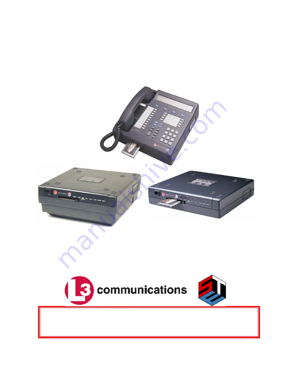
SECURE TERMINAL EQUIPMENT (STE) 

USER’S MANUAL 

Release 2.6 

Rev A January 2008 

THE INFORMATION CONTAINED HEREIN IS SUBJECT TO THE U.S. EXPORT CONTROL LAWS 
AND MAY NOT BE EXPORTED, RELEASED, OR DISCLOSED TO FOREIGN PERSONS INSIDE OR 
OUTSIDE THE U.S. WITHOUT OBTAINING PROPER APPROVALS. 

Control Number:  K000

11722 

Summary of Contents for Office STE

Page 1: ...SECURE TERMINAL EQUIPMENT STE USER S MANUAL Release 2 6 Rev A January 2008 THE INFORMATION CONTAINED HEREIN IS SUBJECT TO THE U S EXPORT CONTROL LAWS AND MAY NOT BE EXPORTED RELEASED OR DISCLOSED TO FOREIGN PERSONS INSIDE OR OUTSIDE THE U S WITHOUT OBTAINING PROPER APPROVALS Control Number K00011722 ...

Page 2: ...Copyright 2006 L 3 Communications Corporation ...

Page 3: ...ements Unpacking inspection instructions familiarization Rear panel arrangements of all STEs and Installation instructions connection programming and testing Chapter 3 Controls Indicators and Interfaces is intended for all audiences It provides A descriptive overview of the STE Identifies front panel keys buttons indicators the alphanumeric display for the Office and Tactical STEs and Identifies f...

Page 4: ...all hold Call transfer and Conference call ISDN Voice Calls Achieving highest quality of service Initiating calls Answering calls Non secure call hold Secure call hold Call transfer Conference call STE secure casual conference and Managing multiple calls TRI TAC Voice Calls Initiating calls Answering calls Calls to and from PSTN terminals Call hold Call transfer and Conference call BDI Voice Calls...

Page 5: ...offers an RJ 45 connection for an Integrated Service Digital Network ISDN a DB 25 serial connection for a local PC or FAX and a DB 9 connection for a power supply The Office Wedge provides an RJ 11 connection to a Public Switched Telephone Network PSTN The Tactical Wedge also provides a RJ 11 connection for PSTN either a Molex connector or spring posts for a Tri Service Tactical Communications TRI...

Page 6: ... Non secure Hold Non secure Transfer Non secure Conference 38 4 kbps Asynchronous Data Rates Release 1C STU III Rekey STE Rekey KOV 14 Crypto Card Reprogramming 8510 Feature Set TPA Transfer STU III over CVSD STU Secure Dial Secure Hold Black Digital Interface BDI Release 2 0 Future Narrowband Digital Terminal FNBDT 2 4 kbps MELP Commercial V 32 Modem Wireless Interoperability with Type 1 wireless...

Page 7: ...tion Control Software Versions are shown in Table 4 2 NOTE The typographic conventions used in this manual include using San Serif fonts as follows Sans Serif font such as this is used for all normal text SAN SERIF BOLD uppercase such as this is used to identify interface ports and control keys except the Soft Keys For example When addressing the ISDN Interface Port it would be shown as ISDN PORT ...

Page 8: ...ages Page s Release a j 2 6 i xiv 2 6 1 1 1 6 2 6 2 1 2 48 2 6 3 1 3 12 2 6 4 1 4 40 2 6 5 1 5 24 2 6 6 1 6 24 2 6 7 1 7 28 2 6 8 1 8 24 2 6 9 1 9 24 2 6 10 1 10 20 2 6 11 1 11 6 2 6 12 1 12 4 2 6 Index 1 Index 18 2 6 FP 1 FP 4 2 6 ...

Page 9: ...STE User s Manual Revision Log Rel 2 6 g Revision Log Revision Change Summary September 2007 Release 2 6 A January 2008 Release 2 6 ...

Page 10: ...ture Button CIK Crypto Ignition Key CIM Compromised Information Message CKL Compromised Key List CO Central Office CSA Canadian Standards Association CSD Circuit Switched Data CSV Circuit Switched Voice C UL Canadian Underwriters Laboratory CVSD Continuously Variable Slope Delta Modulation DAO Department Agency Organization DCE Data Communications Equipment DMS 100 Digital Multiplex System telepho...

Page 11: ...Significant Bit MELP Mixed Excitation Linear Predictive MLPP Multi Level Precedence Preemption MSB Most Significant Bit MSE Mobile Subscriber Equipment MU Multiple Universal for key sets NACK NAK Negative Acknowledgement NI 1 National ISDN 1 NI 2 National ISDN 2 NSA National Security Agency NSV Non Secure Voice NT 1 Network Termination Device U to S T interface PC Personal Computer IBM compatible ...

Page 12: ...te Voice Data ISDN PSTN STE RI STE Remote Voice Data ISDN only STE RT STE Remote Voice Data ISDN PSTN TRI TAC and BDI STU III Secure Telephone Unit III PSTN only SV Secure Voice TPA Terminal Privilege Authority TRI TAC TRI service TACtical Communications TSG Telephone Security Group U 2 wire ISDN interface UL Underwriters Laboratory UL 1950 Underwriters Laboratory standard UPV User Privileges VAC ...

Page 13: ... Requirements 2 6 2 3 4 Order Your FORTEZZA PLUS KRYPTON ENHANCED CRYPTOCARD 2 7 2 4 GENERAL INSTALLATION PROCEDURES 2 7 2 4 1 Wall Mounting Instructions for Office and Tactical STEs 2 7 2 4 2 Install Handset 2 9 2 4 3 Connect the Console Terminal 2 9 2 4 4 Connect Power 2 9 2 4 5 Install Program and Connect Service s 2 10 2 5 INSTALL ISDN 2 11 2 5 1 ISDN Pre installation Requirements 2 11 2 5 2 S...

Page 14: ...IEW 3 1 3 1 1 Crypto Card Slot 3 1 3 1 2 Crypto Card Ejector Button 3 1 3 1 3 Front Panel 3 1 3 1 4 Terminal Reset 3 7 3 1 5 Audible Alerts 3 7 3 2 CEU DATA STE STE R STE RI STE RT OVERVIEW 3 7 3 2 1 FRONT PANEL 3 7 3 2 2 STE TOOL STE VIRTUAL FRONT PANEL 3 9 Chapter 4 TPA FUNCTIONS 4 1 4 1 CLASS OF USERS 4 1 4 1 1 TPA 4 1 4 1 2 User 4 1 4 2 FORTEZZA PLUS KRYPTON ENHANCED CRYPTOCARD 4 1 4 2 1 Crypt...

Page 15: ...EY 6 19 6 5 REMOVE TERMINAL CARD ASSOCIATION 6 21 6 6 VIEW CKL CIM 6 22 6 6 1 View CKL Version 6 23 6 6 2 View CIM Version 6 23 6 7 ZEROIZE TERMINAL 6 24 Chapter 7 CALLS 7 1 7 1 GENERAL MANAGEMENT 7 1 7 1 1 Voice Call Management Overview 7 2 7 1 2 Crypto Card Insertion Removal 7 3 7 1 3 Initiating Voice Calls 7 4 7 1 4 Special Dialing Procedures 7 4 7 1 5 In Call Operations 7 5 7 1 6 Terminating a...

Page 16: ... Auto_Answer 8 3 8 3 4 Data Port 8 3 8 4 Concept of Operation 8 3 8 4 1 Remote Authentication 8 3 8 4 2 Remote Control States 8 4 8 4 3 Secure Dial 8 6 8 5 AT INTERFACE 8 7 8 5 1 General Rules of Operation 8 7 8 5 2 AT Commands 8 7 8 6 Remote Control Examples 8 23 8 6 1 Dialing an Outgoing Call on PSTN 8 23 8 6 2 Manually Answer an Incoming Call 8 23 8 6 3 Auto_Answer an Incoming Call 8 23 Chapter...

Page 17: ...p 10 2 10 1 3 Software Script 10 2 10 1 4 Procedures to Load Electronic ACL Files 10 3 10 2 STE TOOLSET PROGRAM 10 3 10 2 1 STE Toolset Program General Information 10 3 10 2 2 STE Virtual Front Panel Tool 10 7 10 2 3 Software Download Tool 10 18 Chapter 11 USER MAINTENANCE 11 1 11 1 PREVENTIVE MAINTENANCE 11 1 11 2 CLEANING 11 1 11 3 SELF TEST AND SOFTWARE VERIFICATION 11 1 11 4 SOFTWARE VERSION N...

Page 18: ...re 2 21 ADVANCED TERMINAL SETTINGS FOR INSTALLATION PERSONNEL Menu 2 19 Figure 2 22 STU III ACK NACK ENABLED Menu 2 20 Figure 2 23 STU SCIP EXTENDED TIMEOUT Menu 2 20 Figure 2 24 STU SCIP EXTENDED TIMEOUT Menu 2 20 Figure 2 25 STE EXTENDED TIMEOUT Menu 2 21 Figure 2 26 ENTER STE EXTENDED TIMEOUT Menu 2 21 Figure 2 27 Fade Timeout Menu 2 22 Figure 2 28 ENTER FADE TIMEOUT Menu 2 22 Figure 2 29 INITI...

Page 19: ...nu 2 45 Figure 2 75 Initial Call SECURE COMMUNICATIONS DISABLED Menu 2 47 Figure 2 76 Initial Call NON SECURE MODE Dial Menu 2 47 Figure 2 77 Initial Call ALERTING Menu 2 47 Figure 2 78 Initial Call NON SECURE MODE Menu 2 47 Figure 3 1 Office and Tactical Desk Set Overview 3 1 Figure 3 2 Office and Tactical STE Desk Set Front Panel 3 3 Figure 3 3 Alphanumeric Display Arrangement 3 3 Figure 3 4 Scr...

Page 20: ...Level Menu 4 25 Figure 4 42 Secure Data Minimum Security Level Menu 4 25 Figure 4 43 Secure Data Maximum Security Level Menu 4 26 Figure 4 44 Secure Voice Application Menu 4 26 Figure 4 45 Secure Voice ACL Menu 4 26 Figure 4 46 Secure Voice Security Level Menu 4 27 Figure 4 47 Secure Voice Minimum Security Level Menu 4 27 Figure 4 48 Secure Voice Maximum Security Level Menu 4 28 Figure 4 49 Access...

Page 21: ...ntrol Menu 5 12 Figure 5 26 Initial Secure Mode Menu 5 13 Figure 5 27 Remote Control Menu 5 13 Figure 5 28 Card Privileges Menu 5 13 Figure 5 29 Secure Access Control System Menu 5 14 Figure 5 30 Secure Data Application Menu 5 14 Figure 5 31 Secure Data ACL Menu 5 15 Figure 5 32 Secure Data Maximum Minimum Security Level Menu 5 15 Figure 5 33 Secure Voice Application Menu 5 15 Figure 5 34 Secure V...

Page 22: ...Non secure To Menu 6 11 Figure 6 30 STE ISDN STE SCIP Rekey in Progress Going Secure To Menu 6 11 Figure 6 31 SDNS Rekey in Progress Status Menu 6 11 Figure 6 32 SDNS Rekey Successful Menu 6 12 Figure 6 33 View Card Key Data Menu 6 12 Figure 6 34 STU III Key Data Key ID Menu 6 13 Figure 6 35 STU III Key Data DAO Code Menu 6 13 Figure 6 36 STU III Key Data Key Classification Menu 6 13 Figure 6 37 S...

Page 23: ...ne 1 Call In Progress Menu 7 19 Figure 7 26 Line 1 Call Hold Menu 7 20 Figure 7 27 Line 2 Call In Progress Menu 7 20 Figure 7 28 Line 2 Call On Hold Menu 7 20 Figure 7 29 Line 1 Call In Progress Menu 7 20 Figure 7 30 Line 2 Call In Progress Menu 7 21 Figure 7 31 TRI TAC Auto Secure Off Hook Menu 7 21 Figure 7 32 TRI TAC Traditional Off Hook Menu 7 22 Figure 7 33 TRI TAC Secure Only Off Hook Menu 7...

Page 24: ...Options Terminal Type Default Window 10 10 Figure 10 6 STE Toolset Options Terminal Type 10 11 Figure 10 7 STE Toolset Options Comm Port 10 12 Figure 10 8 STE Toolset Options Debug Flags 10 13 Figure 10 9 STE Toolset Options Override 10 14 Figure 10 10 STE Toolset Help About 10 15 Figure 10 11 STE Local Control From a Distance 10 16 FO 1 User Installer Tree 1 FO 2 User Tree 2 FO 3 MODE Tree 3 FO 4...

Page 25: ...TN 2 25 Table 2 19 International PSTN Wedge Characteristic Settings 2 27 Table 2 20 International PSTN Wedge Default Settings 2 29 Table 2 21 TRI TAC Connector Pin outs 2 35 Table 2 22 Active Network Port TRI TAC 2 36 Table 2 23 BDI EIA 530A EIA 232 Connector Pin outs 2 41 Table 2 24 Active Network Port BDI 2 41 Table 2 25 Red Serial Data Port Pin Outs 2 46 Table 4 1 Terminal Privilege Defaults 4 ...

Page 26: ...List of Tables STE User s Manual xiv Rel 2 6 This page intentionally left blank ...

Page 27: ...desk set shown in Figure 1 2 is made up of two parts the STE and the Wedge 1 The STE contains ISDN Integrated Services Digital Network and data processing circuits common to all STE configurations 2 The Wedge contains additional circuits that provide access to other telecommunications systems as described below The Office Desk Set is available in two configurations ISDN only and ISDN and PSTN Publ...

Page 28: ...ne Unit Type III terminals Narrowband devices i e OMNI and wireless FNBDT Future Narrow Band Digital Terminal and DNVT Digital Non secure Voice Terminals Secure voice interoperable with other STE STU III or SCIP FNBDT Terminals like the OMNI Terminals Secure facsimile interoperable with FAX units supported by other STE STU III or SCIP Terminals like the OMNI Terminals and Secure data interoperable...

Page 29: ...rminals The CEU STE R STE RI and STE RT provide secure voice interoperability with STE and STU III and SCIP terminals when they function as a gateway device for interfacing red switches with STE STU III and SCIP terminals on black dial up PSTN or ISDN systems 1 3 L 3 STE SERVICE CENTER L 3 Communications Communication Systems East STE Service Center 11 Federal Street Camden NJ 08103 1013 Phone 800...

Page 30: ...8 7 2 9 6 12 14 4 16 8 19 2 21 6 24 kbps TRI TAC BDI 530A and BDI 232 2 4 4 8 9 6 kbps Interfaces Network Host Data ISDN S T BRI 1B D 2B D RJ 45 PSTN RJ 11C 2 wire TRI TAC MSE wireline modem 4 wire Tactical STE only BDI EIA 232 or BDI EIA 530A Tactical STE only EIA 232 or EIA 530A Interoperability STU III SCIP Terminals like the OMNI DNVT Tactical STE only ISDN NI 1 NI 2 5ESS DMS 100 DEFINITY Euro...

Page 31: ... not use your STE near a gas leak Avoid using your STE during an electrical storm There is a remote risk of electric shock from lightning Use caution when installing or modifying telephone lines Never install telephone jacks in wet locations unless the jack is specifically designed for wet locations Never touch terminals or bare telephone wires unless the telephone line has been disconnected at th...

Page 32: ...Introduction STE User s Manual 1 6 Rel 2 6 This page intentionally left blank ...

Page 33: ... shipping documentation prior to signing for the shipment When the shipping container is opened inventory the contents refer to Table 2 1 through Table 2 7 and inspect each item for damage If the STE Terminal an assembly made up of a base STE and either an Office Wedge or a Tactical Wedge shows signs of damage DO NOT proceed with the installation Send the terminal back to L 3 Communications Refer ...

Page 34: ...sole Cable K10047819 1 1 STE Software and Documentation Support CD ROM K10048750 series Table 2 5 STE RT Packing Container Contents Quantity Description Part Number 1 STE RT Terminal PSTN K10048499 504 REL 2 HW K10048499 507 REL 2 HW 1 AC DC Power Supply K10046396 1 1 Handset Cord Coiled TC08 BLK 12FT 1 ISDN Line Cord URT45 M4N 12 BK 1 PSTN Line Cord H1442 14 ND 1 Console Cable K10047819 1 1 STE S...

Page 35: ...ON PORT is a PCMCIA expansion slot for future network interfaces such as a VOIP interface RED SERIAL DATA PORT 1 ISDN TERMINATION SWITCHES PSTN PORT ISDN PORT TRI TAC PORT Tactical STEs Only BDI PORT Tactical STEs Only RED EXPANSION PORT BLACK EXPANSION PORT POWER PORT Office and Tactical STEs PSTN PORT ISDN PORT POWER PORT CEU Data STE STE R STE RI and STE RT TRI TAC PORT STE RT Only BDI PORT STE...

Page 36: ...on the newer STE versions Use this port to connect your STE to the TRI TAC service 2 2 2 3 Black Digital Interface EIA 530A EIA 232 Port The Black Digital Interface port or the BDI PORT is a 25 pin D connector located in the rear of both the Tactical STE and the STE RT You will use this port to connect to the BDI service You can configure the port as either an EIA 530A or EIA 232 via selections in...

Page 37: ...lled using the STE Power Supply shipped with the unit The Power Supply DC cord DB 9 to power supply is 6 feet long The 6 foot AC cord shipped with the supply for use in the USA is an IEC320 plug on the supply side and a standard 3 prong 110V plug on the other end Users with different requirements must provide an AC cord with an IEC320 plug for the power supply and the power plug required for their...

Page 38: ...equirements apply to the CEU STE RI and STE RT The RED AUDIO PORT an RJ 8 socket is located on the left side of the STEs The pin assignments are shown in Table 2 12 Table 2 12 Red Audio Port Pin out Pin Signal Name 1 Audio In to STE R 2 Audio Out from STE R 3 Audio Out from STE R 4 Audio In to STE R The port consists of differential analog audio input and output signals The audio input signals are...

Page 39: ...GENERAL INSTALLATION PROCEDURES The crypto card is not needed for the installation procedures Therefore your STE can be installed network programming completed and the initial tests performed as soon as the service s are in place When the local facility or Telephone Company representatives have installed the required service s you may proceed with the installation If the Office or Tactical STE des...

Page 40: ... to the STE by the ribbon cable b Carefully rotate the wedge clockwise 180 so the wall mounting holes look like an L rather than a 7 NOTE The ribbon cable should not have more than a half twist 90 c Hold the wedge in position and replace the four Phillips head screws Tighten the four screws hand tight making sure you do not strip the screws or sockets d Remove the Handset Hook by sliding it up and...

Page 41: ...ect the STE Power Supply or user s supply to the STE as follows 1 If installing a CEU STE R STE RI or STE RT connect a PC to the console port and apply power to it NOTE If using other than the STE Power Supply follow the directions provided with the unit or site installation instructions then proceed to step 4 Make sure to connect the POWER PORT first 2 Plug the power supply or user cable into the...

Page 42: ... in detail Install ISDN Paragraph 2 5 Install PSTN Paragraph 2 6 Install TRI TAC Paragraph 2 7 Install BDI Paragraph 2 8 NOTE When more than one service is connected and you change services in the ACTIVE Network Port display it may be necessary to reset your STE After you select a new service i e change from PSTN to ISDN press the MODE MUTE keys to reset the terminal In addition when you change fr...

Page 43: ...r ID function is optional but recommended Additional Call Offerings ACOs Appearances must be at least three If you are using a Lucent 5ESS Switch The line must be set for point to multipoint For Custom Mode the Terminal Type must be set to A If you are configuring a STE for 8510 operations refer to Chapter 9 for additional requirements For additional information about ISDN service ask your service...

Page 44: ...e SPID identifies the available service options There may be one or two SPIDs depending upon the Switch Type and Switch Line Setting A SPID may be up to 20 numbers long Two SPIDs are required for bonding sharing channels for greater bandwidth The DN is your telephone number There may be one or two DNs depending upon the Switch Type and Switch Line Setting Examples of SPIDs and DNs formats are SPID...

Page 45: ...15 ISDN Connector Pin outs Pin Signal Name Pin Signal Name 1 No Connection 5 ISDN RX 2 No Connection 6 ISDN TX 3 ISDN TX 7 No Connection 4 ISDN RX 8 No Connection 2 5 1 3 Additional ISDN Information For additional information for ISDN please go to the government web site at http wired securephone net or http www securephone net then select wired 2 5 2 Set ACTIVE NETWORK PORT to ISDN The STE must h...

Page 46: ...ERMINAL MANAGEMENT menu Figure 2 6 is presented Figure 2 6 TERMINAL MANAGEMENT Menu 2 In the TERMINAL MANAGEMENT menu press SELECT to advance to the NETWORK SETTINGS menu Figure 2 7 Figure 2 7 NETWORK SETTINGS Menu 3 With the NETWORK SETTINGS menu displayed press SELECT to advance to the ACTIVE NETWORK PORT menu Figure 2 8 Figure 2 8 ACTIVE NETWORK PORT ISDN Menu 4 The ACTIVE NETWORK PORT display ...

Page 47: ...D SPID 1 menu Figure 2 10 shows the first SPID assigned to the STE s switch In a new installation this will be blank The aaaaaaaaaaaaaaaaaaaa in the display represents the SPID up to 20 digits Figure 2 10 SERVICE PROFILE ID 1 SPID Menu 1 To set the initial value for SPID 1 or change the value of an existing SPID press CHANGE to advance to the ENTER SERVICE PROFILE ID 1 menu Figure 2 11 Figure 2 11...

Page 48: ...comes available Press DELETE to erase the last digit entered similar to a backspace function When the number has been entered press STORE The display returns to the DIRECTORY NUMBER 1 menu Figure 2 12 3 Press ABORT to return the display to the DIRECTORY NUMBER 1 menu Figure 2 12 4 If no change is required press SCROLL to advance to the SERVICE PROFILE ID SPID 2 menu Paragraph 2 5 6 5 Pressing BACK...

Page 49: ...call capabilities The default setting is 060 Figure 2 15 CONFERENCE FEATURE CODE Menu 1 To change an existing code to one listed in Table 2 14 press CHANGE to advance the display to the ENTER CONFERENCE FEATURE CODE menu Figure 2 16 Figure 2 16 ENTER CONFERENCE FEATURE CODE Menu 2 Using the DIAL PAD KEYS enter the feature value from the table and press STORE The valid range represented by nnn is b...

Page 50: ...s use DELETE to erase the last digit entered This works like a backspace function a If the entry is valid less than 128 the display returns to the TRANSFER FEATURE CODE menu Figure 2 17 b If the entered code is greater than 127 an INVALID ENTRY menu will be displayed Enter the correct code less than 128 and press STORE The display returns to the TRANSFER FEATURE CODE menu Figure 2 17 3 Pressing AB...

Page 51: ...Paragraph 2 5 9 5 Press BACK in the DROP FEATURE CODE menu to return the display to the NETWORK SETTINGS menu Figure 2 7 2 5 9 ADVANCED TERMINAL SETTINGS FOR INSTALLATION PERSONNEL ISDN The Advanced Terminal Settings for Installation Personnel menu is shown in Figure 2 21 Figure 2 21 ADVANCED TERMINAL SETTINGS FOR INSTALLATION PERSONNEL Menu In the ADVANCED TERMINAL SETTINGS FOR INSTALLATION PERSO...

Page 52: ... and 255 The default setting is 0 Figure 2 23 STU SCIP EXTENDED TIMEOUT Menu 1 To change the time press CHANGE to advance the display to the STU III EXTENDED TIMEOUT menu Figure 2 24 Figure 2 24 STU SCIP EXTENDED TIMEOUT Menu 2 Using the DIAL PAD KEYS enter the timeout value in a valid range between 0 and 255 seconds as represented by abc and press STORE If you make a mistake during the entry proc...

Page 53: ...splay returns to the STE EXTENDED TIMEOUT menu Figure 2 25 4 If the entered code is greater than 30 an INVALID ENTRY menu will be displayed Enter the correct code less than 31 then press STORE to return the display to the STE EXTENDED TIMEOUT menu Figure 2 25 5 Pressing ABORT return the display to the STE EXTENDED TIMEOUT menu Figure 2 25 6 If a change is not required or after a new entry is made ...

Page 54: ...CROLL to advance the display to INITIATE DIRECT DIAL Paragraph 2 5 9 5 4 Press BACK to return the display to the NETWORK SETTINGS menu Figure 2 7 2 5 9 5 Set INITIATE DIRECT DIAL This feature supports the United States Navy s Direct Dial program The Navy program developed a new Gateway Interworking Function GW IWF to support the connection of terminals on independent ISDN PSTN networks such as shi...

Page 55: ...rs The INITIATE STE ON VOICE BEARER menu Figure 2 30 shows whether the feature is ENABLED or DISABLED The default setting is ENABLED Figure 2 30 INITIATE STE ON VOICE BEARER Menu 1 To change the setting press CHANGE to toggle between ENABLED or DISABLED 2 If a change is not required or when the setting is made pressing SCROLL advances the display to the STE 210 RECEIVE SECURE DIAL menu Paragraph 2...

Page 56: ... jack If the service provider installed an ISDN U receptacle you must use an NT 1 Interface Adapter Set the adapter s termination switch to 100Ω and plug it into the wall receptacle Plug the Network Cable P N URT45 M4N 12 BK supplied with the STE into the device end of the adapter and the other end into the ISDN PORT When connected proceed to Paragraph 2 11 and make a test call 2 6 INSTALL PSTN 2 ...

Page 57: ... correct setting for your installation Table 2 18 Active Network Port PSTN Setting Default Network Settings Active Network Port must be changed to PSTN ISDN Active Network Port PSTN International Wedge or Active Network Port PSTN Conventional Wedge United States none For International Wedge Advanced PSTN Settings for Installation Personnel defaults vary by country selected but may be changed to me...

Page 58: ...ollowing the procedures in Paragraph 2 6 2 1 If the adapter will be used with the default settings proceed to Paragraph 2 6 3 If the STE is equipped with a Conventional PSTN Adapter proceed to Paragraph 2 6 4 Set PSTN Dialing Mode 2 6 2 1 Configure the International PSTN Adapter NOTE The five switch settings on the International PSTN Adapter must be made before continuing the configuration of the ...

Page 59: ...g switch settings so the circuit board is not damaged Figure 2 36 International PSTN Wedge Arrangement Table 2 19 International PSTN Wedge Characteristic Settings P1 P2 P3 P4 P5 Country 1 2 1 2 1 2 1 2 1 2 DEFAULT ON OFF ON OFF ON OFF ON OFF ON OFF Australia ON OFF OFF ON OFF ON ON OFF OFF ON Belgium OFF ON OFF ON OFF ON ON OFF OFF ON Canada ON OFF ON OFF ON OFF ON OFF ON OFF Czech Republic OFF ON...

Page 60: ...lete the switch settings reassemble your STE and connect the handset 5 Apply power to the STE and proceed to Paragraph 2 6 3 2 6 3 Configure the International STE for PSTN Operation Refer to Paragraph 2 6 2 and follow Step 1 through 3 When in the ACTIVE NETWORK PORT display Figure 2 35a press SCROLL once to advance to the ADVANCED PSTN SETTINGS FOR INSTALLATION PERSONNEL menu Figure 2 37 Figure 2 ...

Page 61: ...TN Wedge Default Settings DTMF Levels dBm Country Default Modem Output Level dBm Modem Reference Level dBm Pre Emphasis Curve High Low Hookflash Duration milliseconds Australia 10 0 4 10 12 600 Belgium 8 0 2 7 9 100 Canada 9 0 1 4 6 600 Czech Republic 10 0 2 7 9 100 Denmark 8 0 2 7 9 100 France 8 0 2 7 9 300 Germany 8 0 2 7 9 100 Greece 8 0 2 7 9 100 Hungary 0 0 2 7 9 100 Iceland 8 0 2 7 9 100 Ita...

Page 62: ...o digits appear in the second line Upon entering a digit using the KEYPAD the digit and SOFT KEYS will appear For the default settings by country see Table 2 20 Figure 2 40 ENTER MODEM OUTPUT LEVEL Menu 1 Press STORE to enter the new level into memory and it is used for all calls until changed 2 Press DELETE to erase the number entered similar to a Backspace function and allows a new number to be ...

Page 63: ...enu Figure 2 43 shows the current settings in the second line and provides the means to changes the levels For information on the default settings by country please see Table 2 20 Figure 2 43 DTMF LEVELS Menu 1 Press CHANGE to select one of three present values 2 Press SCROLL to advance the display to the HOOKFLASH DURATION menu Paragraph 2 6 3 7 3 Press BACK to return the display to the ADVANCED ...

Page 64: ... recognize tones or DISABLED The default setting is ENABLED Figure 2 46 PREEMPT TONE DETECTION Menu 1 Press CHANGE to toggle between ENABLED and DISABLED 2 When the setting has been completed press SCROLL to advance the display to the ADVANCED TERMINAL SETTINGS FOR INSTALLATION PERSONNEL menu Paragraph 2 6 6 3 Press BACK to return the display to the NETWORK SETTINGS menu Figure 2 34 2 6 6 ADVANCED...

Page 65: ...DISABLED 2 When the setting is made press SCROLL to advance to the STU SCIP EXTENDED TIMEOUT Paragraph 2 6 6 2 menu also shared by all services 3 Press BACK to return the display to the NETWORK SETTINGS menu Figure 2 34 2 6 6 2 Set STU SCIP EXTENDED TIMEOUT In a secure call attempt based on STU III or SCIP signaling the time allotted for the far end to respond is increased by this value In other w...

Page 66: ...the modem carrier fades before the STE fails the call In other words it defines how long the STE will attempt to maintain an active call STU III if the network fades such as in a cellular network NOTE Although the STE maintains the connection while within this timeout window it may be necessary to automatically resynchronize the STE at the end of the fading interval The FADE TIMEOUT menu Figure 2 ...

Page 67: ...ke a test call 2 7 INSTALL TRI TAC Please note that the followiing TRI TAC pre installation requirements will apply only to the Tactical STE and to the STE RT 2 7 1 TRI TAC Pre installation Requirements The TRI TAC PORT is located on the rear of the Tactical Wedge Two types of TRI TAC interfaces are used in the Tactical STEs The older models use a Molex 43045 0400 connector while the newer models ...

Page 68: ... to TRI TAC The STE must have power applied but should not be connected to the TRI TAC service while making the initial settings You do not need a FORTEZZA PLUS KRYPTON ENHANCED CRYPTOCARD for any installation procedure including placing the initial test call The ACTIVE NETWORK PORT setting determines which service the STE will use to operate Table 2 22 provides a listing of the variables associat...

Page 69: ...K PORT to TRI TAC next you will press SCROLL once to advance to the ADVANCED TERMINAL SETTINGS FOR INSTALLATION PERSONNEL menu Paragraph 2 7 3 6 Press BACK to return the display to the NETWORK SETTINGS menu Figure 2 55 2 7 3 ADVANCED TERMINAL SETTINGS FOR INSTALLATION PERSONNEL TRI TAC The Advanced Terminal Settings for Installation Personnel menu is shown in Figure 2 57 Figure 2 57 ADVANCED TERMI...

Page 70: ...ss CHANGE to toggle between ENABLED and DISABLED 2 When the setting is made press SCROLL to advance to the STU SCIP EXTENDED TIMEOUT Paragraph 2 7 3 2 menu also shared by all services 3 Press BACK to return the display to the NETWORK SETTINGS menu Figure 2 55 2 7 3 2 Set STU SCIP EXTENDED TIMEOUT In a secure call attempt based on STU III or SCIP signaling the time allotted for the far end to respo...

Page 71: ... to maintain the network connection when the modem carrier fades before the STE fails the call In other words it defines how long the STE will attempt to maintain an active call STU III if the network fades such as in a cellular network NOTE Although the STE maintains the connection while within this timeout window it may be necessary to automatically resynchronize the STE at the end of the fading...

Page 72: ...play to the NETWORK SETTINGS menu Figure 2 55 This completes the configuration of the STE for TRI TAC service Proceed to Paragraph 2 7 4 and connect the STE to the TRI TAC service 2 7 4 Connect TRI TAC Port The TRI TAC PORT is located on the rear panel of the Tactical STE Wedge Figure 2 1 If a STE Sleeve is being used refer to Paragraph 2 7 and the instruction sheet provided with the sleeve in lie...

Page 73: ...5 for an EIA 232 interface 2 8 2 Set the ACTIVE NETWORK PORT to EIA 232 or EIA 530A The STE must have power applied but should not be connected to the BDI service while making the initial settings You do not need a FORTEZZA PLUS KRYPTON ENHANCED CRYPTOCARD for any installation procedure including placing the initial test call The ACTIVE NETWORK PORT setting determines which service the STE will us...

Page 74: ...or BDI 530A 5 With your BDI set you will press SCROLL once to advance to the NETWORK RATE menu Paragraph 2 8 3 6 Press BACK to return the display to the NETWORK SETTING menu Figure 2 65 2 8 3 Set NETWORK RATE The NETWORK RATE menu Figure 2 67 shows the data communications rate 2 4 Kbps 4 8 Kbps or 9 6 Kbps set in the STE The default setting is 9 6 Kbps Figure 2 67 NETWORK RATE Menu 1 To change the...

Page 75: ...onnel menu is shown in Figure 2 69 Figure 2 69 ADVANCED TERMINAL SETTINGS FOR INSTALLATION PERSONNEL Menu In the ADVANCED TERMINAL SETTINGS FOR INSTALLATION PERSONNEL 1 Press SELECT to advance to the STU III ACK NACK menu Paragraph 2 8 5 1 2 Press SCROLL or BACK to return the display to the NETWORK SETTINGS menu Figure 2 65 2 8 5 1 Set STU III ACK NACK The STU III ACK NACK menu selects a protocol ...

Page 76: ...press CHANGE to advance the display to the STU III EXTENDED TIMEOUT menu Figure 2 72 Figure 2 72 STU III EXTENDED TIMEOUT Menu 2 Using the DIAL PAD KEYS enter the timeout value in a valid range between 0 and 255 seconds as represented by abc and press STORE If you make a mistake during the entry process use DELETE to erase the last digit entered This works like a backspace function 3 If the entry ...

Page 77: ...ge between 0 and 255 seconds as represented by abc and press STORE If you make a mistake during the entry process use DELETE to erase the last digit entered a If the entry is valid less than 256 the display returns to the FADE TIMEOUT menu Figure 2 73 b If the entered code is greater than 255 an INVALID ENTRY menu will be displayed Enter the correct code less than 256 then press STORE c Press ABOR...

Page 78: ...onnection 13 CTS B Not Used The timing clock for the transmit element is supplied by the DCE the STE via pins 12 and 15 for an EIA 530A interface or just pin 15 for an EIA 232 interface Use a shielded serial cable to connect a PC or FAX unit to the RED SERIAL DATA PORT on the rear of the STE unit All connections to this port must be made with TEMPEST approved full foil and 85 percent braid covered...

Page 79: ...s dialed Figure 2 77 is displayed Figure 2 77 Initial Call ALERTING Menu When the far end party called answers the call Figure 2 78 is displayed Figure 2 78 Initial Call NON SECURE MODE Menu When you have completed your call hang up the handset The display will show a disconnect message for a few seconds and then it will clear When all Network Settings and initial test calls have been completed yo...

Page 80: ...ceive their STE with the TPA already established the privileges set and with the user card s already associated with the STE When the STE privileges have been set and User Crypto Cards established the STE may be issued for use in accordance with local procedures ...

Page 81: ... you have fully seated the card When seated the CARD INSERTED indicator located on the front panel will flash for 5 seconds and then become a solid light NOTE Ensure you load the Crypto Card properly with the images of the key and of the arrow facing up and with the arrow facing into the STE Failure to properly load the card can damage the card and the STE This damage is not covered by the warrant...

Page 82: ...Controls Indicators and Interfaces STE User s Manual 3 2 Rel 2 6 and Crypto Cards as well as call control is accomplished by actuation of various keys The display keys and indicators are described below ...

Page 83: ...splay The Soft Keys are variable function selectors The STE provides four types of displays scrollable Soft Key selection acknowledgement and data entry 3 1 3 1 1 Scrollable Displays When a scrollable display Figure 3 4 is presented you can scroll through the display names that appear in line 1 by pressing SCROLL Soft Key 3 You select the desired display by pressing SELECT Soft Key 1 Options or li...

Page 84: ...o confirm you will be required to press the Soft Key located immediately below the word SELECT in the third line of the display Figure 3 5 Soft Key Selection Display Press Result SELECT When pressed traverses down through the Menu Hierarchy i e TERMINAL MANAGEMENT NETWORK SETTINGS ACTIVE NETWORK PORT Also applies to CHANGE MODIFY USER and VIEW SCROLL When pressed is used to scroll through the menu...

Page 85: ... returns the display to the next higher display 3 1 3 2 Control Keys and Indicators 3 1 3 2 1 Soft Keys The four Soft Keys located below the alphanumeric display provide interaction with the STE as indicated in the bottom line of the display during programming and operation 3 1 3 2 2 Precedence Key and Indicator Press the PREC Precedence key to send the AUTOVON precedence tones available only with...

Page 86: ...e or answer other calls When you press the HOLD button the active call is placed on hold again as with a normal telephone However the CALL LED indicator will flash 0 2 seconds on 0 8 seconds off for the call placed on hold To return to the call on hold press the CALL button with the flashing indicator HOLD is also used while other tasks are being performed such as establishing conference calls or ...

Page 87: ... off hook 3 1 3 7 Programming Keys 3 1 3 7 1 MENU Key MENU is used to enter and exit the menus to view or change the Terminal Management and Card Management settings while the STE is on hook 3 1 3 7 2 MODE Key MODE may be used with the STE on hook or off hook It is used to configure the modes of the STE and to enable Speed Dial setting modifications Settings made via the MODE menus when off hook a...

Page 88: ... the card place your hand in a position to catch the card and apply firm constant pressure to the ejector button 3 2 1 4 Card Inserted Indicator Whenever a Crypto Card is inserted in an activated STE CARD INSERTED will glow YELLOW While the STE initializes the Crypto Card CARD INSERTED flashes at a slow rate When the terminal determines the Crypto Card is invalid or not compatible the CARD INSERTE...

Page 89: ...s is the assigned TPA ZEROIZE should not be used by operational users except in an emergency destruction situation 3 2 2 STE TOOL STE VIRTUAL FRONT PANEL The STE Virtual Front Panel shown in Figure 3 9 provides an alphanumeric display control keys and indicators for the STE Physically the Virtual Front Panel is a software application running on a PC which is connected to the CEU Data STE and STE R...

Page 90: ...Controls Indicators and Interfaces STE User s Manual 3 10 Rel 2 6 DIAL PAD KEYS WINDOWS BANNER SOFT KEYS 4 ALPHANUMERIC DISPLAY MENU KEY MODE KEY Figure 3 9 Virtual Front Panel ...

Page 91: ...el Local Control Mode Enabled The TPA controlled menu item allows a STE R to enable or disable local mode operations When the TPA has enabled STE R Local Mode for a STE R that STE becomes a remotely controlled secure phone which can be physically located away from the user as needed in any non office situations As the STE already has a remote control mode using the red data port and AT commands th...

Page 92: ...Controls Indicators and Interfaces STE User s Manual 3 12 Rev 2 6 This page intentionally left blank ...

Page 93: ...A Card When the card is inserted into an assigned STE it unlocks the security features and allows the TPA to program the STE s security features Responsibilities of the TPA include Setting the STE Security Straps and STE Privileges Downloading STE and Crypto Card Software Upgrades Creating User Cards from Fill Cards Transferring TPA card privileges 4 1 2 User A User is a person who has been given ...

Page 94: ...teries have an expected life of approximately 5 to 7 years Also there are neither program nor visible indications that the battery is failing Thus any problem with the card s power supply battery may become apparent only though errors when the card is installed in the STE 4 2 1 Crypto Card States and Functions The FORTEZZA PLUS KRYPTON ENHANCED CRYPTOCARD can be in either one of two primary states...

Page 95: ...A split of the CIK The B split has been removed and is stored in the STE Because association has removed one of the splits the card is no longer classified and is said to be locked and unclassified Now the User Card only needs to be accountable by serial number Without the User Card being inserted in the associated STE the STE is also unclassified When the User Card is inserted in the associated S...

Page 96: ... User s Manual 4 4 Rel 2 6 Figure 4 2 2 In Figure 4 3A the STE s Associated Crypto Card List registry is empty and the Fill Card designated as a new TPA Card is serial number 10000 To establish a TPA proceed as follows ...

Page 97: ...d Crypto Card serial number 10000 has been designated as the TPA for the STE From now on the STE will check to ensure that the TPA Card in our example serial number 10000 is inserted before allowing any changes to privileges or security related terminal settings Foldout 4 shows the hierarchy of functions associated with the TPA Before we proceed to programming privileges we will complete the discu...

Page 98: ...isplay to NETWORK SETTINGS menu Figure 4 6 SCROLL Advances display to CRYPTO CARD MANAGEMENT menu Chapter 1 BACK Exits Menu function clears display NOTE The Soft Key to be pressed is set in BOLD Press SELECT to advance the display 2 The next display is the NETWORK SETTINGS menu Figure 4 6 Figure 4 6 NETWORK SETTINGS Menu Press Result SELECT Advances display to ACTIVE NETWORK PORT menu Chapter 2 SC...

Page 99: ...efully insert the card into the CRYPTO CARD SLOT When the CARD INSERTED indicator on the front panel lights the STE will process the card and the front panel will display the flashing notification message shown in Figure 4 8 Figure 4 8 VALIDATING TPA CRYPTO CARD Menu 6 When the validation completes the display will present the TERMINAL CONFIGURATION CONTROL menu Figure 4 9 Figure 4 9 TERMINAL CONF...

Page 100: ...TO CARD EJECTOR BUTTON Then insert the Fill Card to be Associated with the STE You can also associate the TPA card with the STE This card would be both a TPA card and a User Card Figure 4 11 CREATE ASSOCIATION Menu Press Result FULL_CIK Executes the creation function ABORT Returns display to REMOVE ASSOCIATION BY NUMBER CREATE A NEW ASSOCIATION menu Figure 4 10 9 When the designated Fill Card is i...

Page 101: ...it B of some User Card that can be carried to another STE for association by the destination STE s TPA The CIK is transferred to the STE under control of the TPA during the establishment the Association If a User Card from one STE original must be associated with another STE destination a Carry Card must be created The holder of the originating User Card must obtain a second Crypto Card that will ...

Page 102: ...E ASSOCIATION Figure 4 15 if Crypto Card is inserted SCROLL Advances display to TRANSFER TPA PRIVILEGES menu if TPA PASSWORD was set if not advances display to AUDIBLE ALERTS menu Paragraph 5 1 4 BACK Returns display to TERMINAL MANAGEMENT menu Paragraph 4 2 3 Press PREPARE 2 The PREPARE REMOTE ASSOCIATION For Inserted User Card menu Figure 4 15 is displayed Figure 4 15 PREPARE REMOTE ASSOCIATION ...

Page 103: ...ess ABORT and the display returns to the REMOVE CRYPTO CARD ASSOCIATION PREPARE REMOTE ASSOCIATION If you want to continue with the operation eject the User Card currently in the STE the Associated User Card and insert the Carry Card Remember the Carry Card is not the associated User Card but a new card a different User Card a new Fill Card or a TPA Card PREPARE REMOTE ASSOCIATION ABORT Insert Car...

Page 104: ...plit B which is now available for transfer to the destination STE 5 Eject the Carry Card and give it to the TPA of the destination STE the Carry Card along with the associated User Card that was used to create the Carry Card 4 2 4 2 Associate User Carry Card The TPA for a specific STE is the only person who can create an association with a Crypto Card Follow the procedures in Paragraph 4 2 3 to as...

Page 105: ...een moved to the STE as CIK Split B under control of the TPA When the association process is completed the secure capabilities of the User Card can now be unlocked in both the original STE and destination STE as is shown in Figure 4 20 NOTE The User Card is associated with the originating STE by one CIK Split and is associated with the destination STE by a different CIK Split A Crypto Card Slot CR...

Page 106: ...rd cannot serve as the TPA Card for any other STE until it is assigned to those STEs as discussed in Paragraph 4 2 2 NOTE When attempting to transfer TPA privileges if an incorrect TPA password is entered 10 times in succession either maliciously or mistakenly the STE will delete the transfer password The TPA will then need to create a new password Inputting the correct password will reset the inc...

Page 107: ...ed to 10 characters digits 0 9 Figure 4 22 ENTER NEW TPA PASSWORD Menu Press Result DONE Advances display to PASSWORD CHANGE SUCCESSFUL menu no shown DELETE Available when first digit of the password is entered in line 2 Acts as a backspace by deleting the last character entered ABORT Return display to CHANGE TPA PASSWORD menu Figure 4 21 When your password is entered press DONE 4 After the passwo...

Page 108: ...gure 4 23 Enter the 10 digit TPA Password and press DONE 3 After the password is processed the STE will display the TPA ESTABLISHMENT SUCCESSFUL Figure 4 25 menu Figure 4 25 TPA ESTABLISHMENT SUCCESSFUL Menu Press Result CONTINUE Advances display to TRANSFER TPA PRIVILEGES menu Press CONTINUE The User Card or Fill Card that was inserted at the beginning of this process now is a TPA 4 4 MENU Hierar...

Page 109: ...is the gateway to all features dealing with the cryptographic cards It is accessed by pressing SCROLL once in the TERMINAL MANAGEMENT menu This menu and its subordinate menus will be discussed in Chapter 1 Figure 4 27 CRYPTO CARD MANAGEMENT Menu Press Result SELECT Advances display to CARD MANAGEMENT PRIVILEGES Select Management Level menu SCROLL Advances display to ZEROIZE TERMINAL menu Figure 4 ...

Page 110: ...e Control Disabled Remote Authentication Enabled Remote Nonsecure Voice Disabled Card Privileges Disabled Secure Access Control System Access Control List Empty Secure Applications Secure Data Applications Enabled Secure Data ACL Disabled Minimum Security Level None Maximum Security Level None Secure Voice Application Enabled Secure Voice ACL Disabled Minimum Security Level None Maximum Security L...

Page 111: ...ontrol The TERMINAL CONFIGURATION CONTROL menu Figure 4 30 is comprised of four major components Initial Secure Mode Change TPA Password Remote Control and Card Privileges Figure 4 30 TERMINAL CONFIGURATION CONTROL Menu Press Result SELECT Advances display to INITIAL SECURE MODE menu Paragraph 4 5 1 1 SCROLL Advances display to SECURE ACCESS CONTROL SYSTEM menu Paragraph 4 5 2 BACK Returns display...

Page 112: ... to CHANGE TPA PASSWORD menu Paragraph 4 5 1 2 For User not TPA advances display to REMOTE CONTROL menu Paragraph 4 5 1 3 BACK Returns display to TERMINAL CONFIGURATION CONTROL menu Paragraph 4 5 1 Press CHANGE to select the desired mode Then press SCROLL to advance to the CHANGE TPA PASSWORD menu 4 5 1 2 Change TPA Password Refer to Paragraph 4 3 1 When DONE is pressed at the ENTER NEW TPA PASSWO...

Page 113: ...or to make changes 3 If you enable Remote Control you will be able to make changes in the TERMINAL CONTROL menu to set either the Front Panel or the Terminal Under Host Port Control remote control options Paragraph 5 1 5 4 5 1 3 1 Remote Authentication The Remote Authentication default setting is enabled see REMOTE AUTHENTICATION ENABLED menu Figure 4 34 Therefore when Remote Control is enabled Re...

Page 114: ...splay to TERMINAL CONFIGURATION CONTROL menu Paragraph 4 5 1 Press SCROLL The TPA of STE R configurations has the ability to Enable or Disable Remote Nonsecure Voice operation The TPA Remote Non Secure Voice menu disabled Figure 4 36 is used to enable remote nonsecure voice operations which allows the terminal to accept and act upon the ATG1 go nonsecure command The default setting for all configu...

Page 115: ...ed as shown below Figure 4 37 CARD PRIVILEGES Menu Press Result CHANGE Only presented to TPA Toggles between ENABLED and DISABLED SCROLL Returns display to TERMINAL CONFIGURATION CONTROL menu Paragraph 4 5 1 BACK Returns display to TERMINAL CONFIGURATION CONTROL menu Paragraph 4 5 1 Press CHANGE to select the desired option ENABLED or DISABLED Press SCROLL to advance the display 4 5 2 Secure Acces...

Page 116: ...a Applications Menu Press Result CHANGE Only presented to TPA and used to toggles between ENABLED and DISABLED SCROLL Advances display to SECURE DATA ACL menu Paragraph 4 5 2 1 2 BACK Returns display to SECURE ACCESS CONTROL SYSTEM menu Paragraph 4 5 2 Press CHANGE to select the desired setting When set to disable observe the notice in the second line Paragraph 5 1 5 Press SCROLL 4 5 2 1 2 Secure ...

Page 117: ...splay to SECDATA MINIMUM SECURITY LEVEL menu Figure 4 42 SCROLL Advances display to SEC VOICE APPL menu Paragraph 4 5 2 1 2 BACK Return display to SECURE ACCESS CONTROL SYSTEM menu Paragraph 4 5 2 Press CHANGE to make changes in either minimum or maximum levels Press SCROLL if no changes are required or after change is made Figure 4 42 Secure Data Minimum Security Level Menu Press Result CHANGE To...

Page 118: ...he menu is displayed when SCROLL is pressed in the SECDATA MAX SEC SECDATA MIN SEC menu Figure 4 44 Secure Voice Application Menu Press Result CHANGE Toggles between the ENABLED and DISABLED menus SCROLL Advances display to SECURE VOICE ACL menu Paragraph 4 5 2 1 5 BACK Returns display to SECURE ACCESS CONTROL SYSTEM menu Paragraph 4 5 2 Press CHANGE to select the desired setting Press SCROLL if n...

Page 119: ...NIMUM SECURITY LEVEL menu Figure 4 47 SCROLL Advances display to SECURE ACCESS CONTROL SYSTEM menu Paragraph 4 5 2 BACK Returns display to SECURE ACCESS CONTROL SYSTEM menu Paragraph 4 5 2 Press CHANGE if security levels must be modified Press SCROLL if changes are not required or after change is made Figure 4 47 Secure Voice Minimum Security Level Menu Press Result CHANGE Toggles between security...

Page 120: ... KMID and or Department Agency Organization DAO lists stored within the STE These are used to validate the identity of connected far end terminals The ACL is empty when shipped from the factory or after the STE is zeroized It is managed installed edited removed by the TPA and can be viewed by all users The TPA can independently enable or disable the ACL for voice and data communications Figure 4 4...

Page 121: ... Figure 4 51 Add ACL Elements Menu Press Result DAO Advances display to ENTER DAO menu Paragraph 4 5 2 2 1 1 1 KMID Advances display to ENTER KMID menu Paragraph 4 5 2 2 1 1 2 BACK Returns display to EDIT ACCESS CONTROL LIST menu Paragraph 4 5 2 2 1 Press either DAO or KMID to access the appropriate list 4 5 2 2 1 1 1 Add DAO Code The ENTER DAO menu provides instructions in line 1 and an entry fie...

Page 122: ...refore press the 3 to create the R The R is shown in display D 3 Enter the numbers 4 5 and 6 using the DIAL PAD KEYS The DAO Code 12R456 is shown in display D Press Result STORE Store the data entered and advances the display to ADDED TO ACL menu Figure 4 53 DELETE Acts as a backspace by deleting the last character entered ABORT Return display to ADD ACL ELEMENTS menu Paragraph 4 5 2 2 1 1 Press t...

Page 123: ...red data and returns menu to ADD ACL ELEMENTS menu Paragraph 4 5 2 2 1 1 DELETE Acts as a backspace by deleting the last character entered ABORT Returns display to ADD ACL ELEMENTS menu Paragraph 4 5 2 2 1 1 Press STORE 4 5 2 2 1 2 Remove ACL Elements Access the REMOVE ACL ELEMENTS menu Figure 4 55 by pressing REMOVE in the EDIT ACCESS CONTROL LIST menu Figure 4 49 This menu allows the removal of ...

Page 124: ...E the Confirmation menu Figure 4 56 is presented Figure 4 56 Remove DAO Code Confirmation Menu Press Result CONFIRM Advances display to DAO REMOVED menu Figure 4 57 ABORT Returns display to REMOVE ACL ELEMENTS menu Paragraph 4 5 2 2 1 2 Press CONFIRM When confirmed the DAO is removed the STE presents the DAO Code Removed menu Figure 4 57 Figure 4 57 DAO Code Removed Menu Press Result CONTINUE Comp...

Page 125: ...VED menu Figure 4 60 ABORT Returns display to REMOVE ACL ELEMENTS menu Paragraph 4 5 2 2 1 2 Press CONFIRM When confirmed the KMID is removed and the STE presents the KMID Removed menu Figure 4 60 Figure 4 60 KMID Removed Menu Press Result CONTINUE Completes the removal of the KMID and returns display to REMOVE ACL ELEMENTS menu Paragraph 4 5 2 2 1 2 or Returns to the EDIT ACCESS CONTROL LIST if t...

Page 126: ...om a PC connected to the RED SERIAL DATA PORT 1 Host Port by selecting FROM PC in the Edit Access Control List menu Refer to Chapter 10 for detailed instructions for downloading the Electronic ACL 4 5 3 Speakerphone Control The SPEAKERPHONE CONTROL menu Figure 4 63 settings may be enabled or disabled for either non secure or secure calls The default setting for both modes is disabled Refer to the ...

Page 127: ...CROLL if no change is required or after change has been made The default setting in the SECURE SPEAKERPHONE menu Figure 4 65 is disabled Figure 4 65 Secure Speakerphone Menu Press Result CHANGE Toggles between ENABLED and DISABLED SCROLL Returns display to SPEAKERPHONE CONTROL menu Figure 4 63 BACK Returns display to SPEAKERPHONE CONTROL menu Figure 4 63 Press CHANGE to change setting Press SCROLL...

Page 128: ...l number through the keypad If the crypto card is available any authorized user can remove the association using the procedures in Paragraph 5 1 2 1 To remove an association by serial number proceed as follows 1 Access the REMOVE ASSOCIATION BY NUMBER CREATE A NEW ASSOCIATION menu Refer to Paragraph 4 5 4 Press REMOVE to present the VIEW ASSOCIATION REMOVE ASSOCIATION menu Figure 4 67 Figure 4 67 ...

Page 129: ...n in the display otherwise a confirmation will be requested Figure 4 69 Remove Crypto Card Association Confirmation Menu Press Result CONFIRM Completes the removal process and returns display to REMOVE ASSOCIATION BY NUMBER CREATE A NEW ASSOCIATION menu Paragraph 4 5 4 ABORT Returns display to ENTER CRYPTO CARD SERIAL NUMBER menu Figure 4 68 Press CONFIRM When CONFIRM was pressed the removal is co...

Page 130: ...vances display to UPDATE SOFTWARE menu SCROLL Advances display to TERMINAL CONFIGURATION CONTROL menu Paragraph 4 5 1 BACK Advances display to TERMINAL PRIVILEGES ASSOCIATION AND SOFTWARE UPDATE MANAGEMENT menu Paragraph 4 5 The current version of the STE Software is available at the STE Web Site and can be downloaded with any web browser Likewise updates to the STE Users Manual may be downloaded ...

Page 131: ... 7522 40 1 13 CEU STE R 1 0 0556 0547 0543 7522 41 1 13 2 2 0561 0552 0548 7529 43 1 13 2 2 1 0563 0558 0552 7529 43 1 13 2 2 2 0569 0561 0552 7529 43 1 13 2 2 3 0575 0567 0552 7529 43 1 13 2 3 0588 0575 0565 7533 43 1 13 2 4 0603 0589 0576 7536 43 1 13 2 5 0615 0602 0582 7801 43 1 13 2 6 0620 0611 0584 7804 43 1 13 NOTE Office Wedge PSTN Tactical Wedge 1 13 and CEU and STE RI no wedge ...

Page 132: ......

Page 133: ...udible Alert Enabled Terminal Control Front Panel Auto answer Disabled Rings Before Auto answer 4 Data Port EIA 232 EIA 530A RED SERIAL DATA PORT EIA 232 Remote Control Data Port Rate 38 4 115 kbps 38 4 Handset Sidetone Enabled Ring Selection Standard Ring Terminal Test Initiate Terminal Test Initiate Front Panel Test 5 1 USER SETTINGS The Main Menu Hierarchy is discussed in Paragraph 4 4 The User...

Page 134: ...graph 5 1 1 SCROLL Advances display to TERMINAL AUDIT INFORMATION menu Paragraph 5 1 1 BACK Returns display to TERMINAL MANAGEMENT menu Figure 5 1 Press SCROLL 5 1 1 Terminal Audit Information The TERMINAL AUDIT INFORMATION menu Figure 5 4 is available to all you The menu is accessed by pressing SCROLL in the Terminal Privileges Associations and Software Update Management menu or if the STE is in ...

Page 135: ...PA Configuration TPA Menu Press Result SCROLL Advances display to CURRENT TPA SOFTWARE SERIAL menu Figure 5 6 BACK Returns display to TERMINAL AUDIT INFORMATION menu Figure 5 4 Press SCROLL When SCROLL is pressed the CURRENT TPA SOFTWARE SERIAL menu Figure 5 6 is displayed and you can view CURRENT TPA indicates the TPA currently established for the STE SOFTWARE SERIAL the identifier for the BOOT p...

Page 136: ...K or as 1024K Figure 5 9 NP Memory Display Press Result SCROLL Returns display to TERMINAL AUDIT INFORMATION menu Figure 5 4 BACK Returns display to TERMINAL AUDIT INFORMATION menu Figure 5 4 At the TERMINAL AUDIT INFORMATION menu Figure 5 4 press SCROLL to advance to the REMOVE CRYPTO CARD ASSOCIATION PREPARE REMOTE ASSOCIATION menu see Paragraph 5 1 2 5 1 2 Remove Crypto Card Association Prepare...

Page 137: ...revent a person from using a STE that they were previously authorized to use but permission has been suspended or revoked and the TPA is not immediately available The person doing the removal may be any user perhaps a Watch Officer but the card being removed from association must be in their possession The TPA should be notified of all removals When REMOVE was pressed in the REMOVE CRYPTO CARD ASS...

Page 138: ...e of two ways 1 Press SCROLL in the REMOVE CRYPTO CARD ASSOCIATION PREPARE REMOTE ASSOCIATION menu Figure 5 10 or 2 If the STE is in an idle state press MENU SELECT and then SCROLL as necessary until the display Figure 5 13 appears Figure 5 13 Audible Alerts Menu Press Result CHANGE Toggles between ENABLED and DISABLED SCROLL Advances display to TERMINAL CONTROL menu Paragraph 5 1 5 if Remote Cont...

Page 139: ...e of two ways 1 If the STE is in the TERMINAL CONTROL menu Figure 5 14 press SCROLL 2 If the STE is in an idle state press MENU SELECT and then SCROLL as necessary until the display Figure 5 15 appears Figure 5 15 Auto_Answer Menu Press Result CHANGE Toggles between ENABLED and DISABLED SCROLL If ENABLED advances display to RINGS BEFORE AUTO ANSWER menu Paragraph 5 1 6 1 If DISABLED advances displ...

Page 140: ...LL if no change is required or after change has been made NOTE When Remote Control is enabled the number of rings is reset to zero 0 disabling Auto_Answer See Paragraph 8 3 3 5 1 7 Data Port The RED SERIAL DATA PORT 1 may be set for EIA 232 default or EIA 530A interoperability by all authorized users Refer to the menu hierarchy shown in the foldouts and the default setting shown in Table 5 1 The D...

Page 141: ...selected the STE will operate at the Remote Control Data Port rate when accepting remote control commands but will operate at the selected synchronous data rate when transferring data traffic The default remote control data port rate setting is 38 4 kbps Figure 5 19 Remote Control Data Port Rate Menu Press Result CHANGE Toggles between 38 4 Kbps and 115 Kbps SCROLL Advances display to HANDSET SIDE...

Page 142: ...lay Figure 5 21 Figure 5 21 Ring Selection Menu Press Result CHANGE Toggles among six selections STANDARD and ALTERNATE RING 1 5 SCROLL Advances display to INITIATE TERMINAL TEST INITIATE FRONT PANEL TEST menu Paragraph 5 1 11 BACK Return display to TERMINAL MANAGEMENT menu Figure 5 1 Press CHANGE as often as necessary to select the desired ring The STE will ring with the unique sound for each set...

Page 143: ...ure self tests will be performed If the card is not inserted only the non secure self tests will be performed If an error occurs during the self test the following display will be presented Figure 5 23 Record the error code s and call the STE Service Center Paragraph 12 1 Figure 5 23 Failure Codes Menu Where hhhh Host Processor error code ffff Front Panel error code nnnn Network Processor error co...

Page 144: ...EM menu Figure 5 29 BACK Returns display to TERMINAL PRIVILEGES ASSOCIATION AND SOFTWARE UPDATE MANAGEMENT menu Figure 5 3 Press SELECT 2 Initial Secure Mode The INITIAL SECURE MODE menu Figure 5 26 determines whether the STE will automatically initiate a secure call upon completion of dialing Three modes are available Traditional The STE will proceed to a non secure voice call unless changed whil...

Page 145: ...mode is enabled advances to REMOTE AUTHENTICATION BACK Return display to TERMINAL CONFIGURATION CONTROL menu Figure 5 25 Press SCROLL 4 Card Privileges CARD PRIVILEGES Figure 5 28 determines if you are authorized to remove crypto card association under Crypto Card Management functions from a STE The default setting is disabled disallowing anyone but the TPA from making changes to Crypto Card privi...

Page 146: ...Secure Applications SECAPP control the secure data and secure voice operations security parameters by enabling allowing or disabling disallowing the application if associated ACLs are enabled or disabled and sets the minimum and maximum operational classification levels for each when enabled a Secure Data Application The SECURE DATA APPL menu Figure 5 30 shows if the STE will accept and place secu...

Page 147: ...cations as established by the TPA Figure 5 32 Secure Data Maximum Minimum Security Level Menu Press Result SCROLL Advances display to SEC VOICE APPL menu Figure 5 33 BACK Returns display to SECURE ACCESS CONTROL SYSTEM menu Figure 5 29 Press SCROLL 8 Secure Voice Application The SECURE VOICE APPL menu Figure 5 33 shows if the STE will accept and place secure voice calls to far end terminals with c...

Page 148: ...nu Figure 5 35 shows both Maximum and Minimum security level settings for voice communications as established by the TPA Figure 5 35 Secure Voice Maximum Minimum Security Level Menu Press Result SCROLL Returns display to SECURE ACCESS CONTROL SYSTEM menu Figure 5 29 BACK Returns display to SECURE ACCESS CONTROL SYSTEM menu Note We recommend that you review the SECAPP settings first then ACL Figure...

Page 149: ...e 5 38 lists the codes currently assigned in the Access Control List that can be used to identify far end STEs in automated operations Figure 5 38 ACL DAOs Menu Press Result PREV Scrolls to the preceding display if available NEXT Scrolls to the next sequential display if available BACK Returns display to VIEW ACCESS CONTROL LIST menu Figure 5 37 Press PREV and or NEXT to view all DAO listings Then...

Page 150: ...akerphone in non secure and secure operations The default setting for both modes is disabled Figure 5 40 Speakerphone Control Menu Press Result SELECT Advances display to NONSECURE SPEAKERPHONE menu Figure 5 41 SCROLL Advances display to TERMINAL CONFIGURATION CONTROL menu Figure 5 25 BACK Advances display to TERMINAL PRIVILEGES ASSOCIATION AND SOFTWARE UPDATE MANAGEMENT menu Figure 5 3 Press SELE...

Page 151: ... TAC circuits voice modes The ADPCM CELP and LPC 10e modes apply to secure voice Mode settings can be made either on hook or off hook The on hook settings are stored in the STE and apply to all calls made The off hook settings are in effect only for the call in progress 5 3 1 On hook Mode Settings To set the Secure Signaling Mode RED SERIAL DATA PORT mode and rate STU III voice mode or to configur...

Page 152: ...CURE DATA A115 STU SECURE VOICE CELP If a change is necessary for either mode press CHANGE to advance to the SECURE DATA Mode Menu If the present settings are correct press SCROLL to advance to the SCIP LINE QUALITY menu Figure 5 45 Figure 5 45 SCROLL Advances display to SCIP LINE QUALITY menu Figure 5 48 BACK Exits the MODE menus The current secure data and voice settings for the STE are presente...

Page 153: ...te is presented Then press SCROLL to advance to the STU SECURE VOICE menu If you have completed all changes press BACK Figure 5 47 Secure Voice Menu Either 2 4 Kbps LPC 10e or 4 8 Kbps CELP Press Result CHANGE Toggles between the 2 4 kbps LPC 10e and 4 8 kbps CELP SCROLL Returns display to MODE SETTING menu Figure 5 44 BACK Returns display to MODE SETTING menu Figure 5 44 If you choose to modify t...

Page 154: ...lection while off hook Press MODE to display the SECURE SIGNALING MODE menu Figure 5 43 and follow the procedures to make the settings and then press MODE or BACK to clear the display Remember in order for off hook changes to Signaling Selection settings to take effect the call must be transitioned to NONSECURE and the secure session must be reinitiated Also remember that off hook settings only ho...

Page 155: ...DIAL key you want to program The display shows the entry menu Figure 5 49 Figure 5 49 Speed Dial Number Entry Menu Where xx is the Speed Dial Key number 1 10 Press Result BACK Returns the STE to the MODE menu 3 Whether a number is presently assigned to the key or not when you enter the first digit for a new number the display will present the action menu Figure 5 50 The number may be up to 25 char...

Page 156: ...o memory repeat step 2 through 4 6 To enter the name or number of the person or organization next to a particular SPEED DIAL key follow these steps 7 Remove the plastic faceplate covering the speed dial card by pressing the top and bottom together and lifting it up 8 Remove the card 9 Write or type the name or number associated with the key in the appropriate space on the card 10 Replace the card ...

Page 157: ...indicated by BOLD ITALIC type in the Press column of the table which we state again following the figure title The CRYPTO CARD MANAGEMENT menu Figure 6 1 is contained within the subordinate menus of TERMINAL MANAGEMENT and is accessed by pressing MENU and then pressing SCROLL Figure 6 1 Crypto Card Management Menu Press Result SELECT Advances display to CARD MANAGEMENT PRIVILEGES menu Paragraph 6 ...

Page 158: ...y to VIEW CARD KEY DATA Paragraph 6 3 BACK Returns display to CRYPTO CARD MANAGEMENT Press SELECT 6 2 1 Update Rekey Phone Number Perform Rekey The UPDATE REKEY PHONE NUMBER PERFORM REKEY menu Figure 6 4 provides the gateway to change the telephone numbers for the rekey center facility or to download new crypto keys to the User Card Access to the UPDATE REKEY PHONE NUMBER PERFORM REKEY menu from t...

Page 159: ...K Returns display to REKEY FUNCTIONS Paragraph 6 2 Press STU III 6 2 1 1 1 STU III Rekey Phone Number Update In the examples below Figure 6 6 empty is shown when the STE is at default zeroized If a number is in memory it will be shown i e 19993456789 Figure 6 6 STU III Enter New Number to Change Menu Press Result BACK Returns display to UPDATE STORED PHONE NUMBER Paragraph 6 2 1 1 As you enter the...

Page 160: ...ne Number Update The SDNS REKEY PHONE NUMBER SELECT TYPE menu Figure 6 8 provides the ability to select the memory supporting either STE or SCIP rekey operations Figure 6 8 SDNS Rekey Phone Number Select Type Menu Press Result STE Advances display to Enter New Number to Change menu Figure 6 9 SCIP Advances display to Enter New Number to Change menu Figure 6 9 BACK Returns display to Update Stored ...

Page 161: ...ng the Rekey telephone numbers press BACK two times to return to the REKEY FUNCTIONS menu Paragraph 6 2 Then press SELECT to advance to the UPDATE REKEY PHONE NUMBER PERFORM REKEY menu Figure 6 4 Press REKEY to advance to Perform Rekey Paragraph 6 2 6 2 2 Perform Rekey The Perform Rekey function allows you to update the STU III and or SDNS crypto keys on the User Card presently installed in the ST...

Page 162: ...ed nor will it notify you of incoming calls When the STE is configured for ISDN and an incoming call is received the STE will provide a BUSY indication to the network The STU III REKEY MODE menu Figure 6 13 is available when 1 STU III was pressed in the PERFORM REKEY menu 2 The STE is configured for ISDN or TRI TAC digital networks or PSTN analog networks 3 A User Card an associated crypto card co...

Page 163: ...d as a non secure call If you are operating on ISDN the Proceeding To menu Figure 6 14 and the subsequent menus are displayed If you are operating in PSTN or TRI TAC proceed to Figure 6 17 Figure 6 14 STU III ISDN STU III Rekey in Progress Proceeding To Menu Figure 6 15 ISDN STU III Rekey in Progress Alerting Menu Figure 6 16 ISDN STU III Rekey in Progress Non secure To Menu Once the call has been...

Page 164: ...tion in the second line in menus Figure 6 18 through Figure 6 23 is replaced with the true value i e KEY CLASSIFICATION TOP SECRET Figure 6 19 ISDN PSTN or TRI TAC STU III Rekey in Progress Key ID Menu Figure 6 20 ISDN PSTN or TRI TAC STU III Rekey in Progress Key Exp Menu Figure 6 21 ISDN PSTN or TRI TAC STU III Rekey in Progress Key Class Menu CLASSIFICATION LINE 1 REKEY DAO DESCRIPTOR SCROLL CL...

Page 165: ... Rekey call may be placed and the STE will not allow calls to be answered nor will it notify you of incoming calls When the STE is configured for ISDN and an incoming call is received the STE will provide a BUSY indication to the network The SDNS REKEY MODE function is available when 1 SDNS was pressed in the PERFORM REKEY menu 2 The STE is configured for ISDN or PSTN SCIP 3 A User Card associated...

Page 166: ... in memory Whichever number is used the call to the KPF is connected by pressing GO Figure 6 26 SDNS Rekey Mode Dial Menu Where XXXXXXXXXXX is the KPF telephone number and YYYYY shows the mode selected in Figure 6 25 as either STE or SCIP Press Result GO At completion of dialing if connection failed advances display to NETWORK REJECTED CALL PLEASE HANG UP In either STE or SCIP mode with the STE se...

Page 167: ...e either REQUEST or RESPONSE depending if your request is being processed or if the rekey response is in progress A 4 window bar shows the progression of the identified task Figure 6 31 SDNS Rekey in Progress Status Menu Various error conditions are possible during an SDNS Rekey attempt Some errors are managed automatically by the STE other errors are recoverable by placing the Rekey call again an...

Page 168: ...TA menu or access either to the ZEROIZE KEY menu or to the VIEW CKL VERSION NUMBERS VIEW CIM VERSION NUMBER menu depending on the card privilege setting Figure 6 33 View Card Key Data Menu Press Result SELECT Advances display to STU III KEY DATA KEY ID menu Paragraph 6 3 1 SCROLL If card privilege is enabled advances display to ZEROIZE KEY Paragraph 6 4 If privilege is disabled advances display to...

Page 169: ...ragraph 6 3 2 SCROLL Advances display to STU III KEY DATA KEY CLASSIFICATION Figure 6 36 BACK Returns display to VIEW CARD KEY DATA Paragraph 6 3 Press SCROLL 3 Figure 6 37 provides the classification of the key in the second line of the display The menu also provides access to the next STU III KEY DATA menu or to the SDNS KEY DATA menu Figure 6 36 STU III Key Data Key Classification Menu AAAAAAAA...

Page 170: ...Press Result NEXT Advances display to SDNS N KEY DATA KEY ID Paragraph 6 3 2 SCROLL Advances display to STU III KEY DATA KEY STATE Figure 6 39 BACK Returns display to VIEW CARD KEY DATA Paragraph 6 3 Press SCROLL 6 Figure 6 39 provides the state of the key in the second line of the display This is the last menu in the STU III KEY DATA series This menu provides access to the SDNS KEY DATA menu or r...

Page 171: ... provides the identification number for the key in the second line of the display The menu also provides access to the next SDNS menu for the present set or to the next sequential key set Figure 6 40 SDNS Key Data Key ID Menu N key set number AAAAAA Key ID KMID Press Result NEXT Advances display to next SDNS N KEY DATA KEY ID Next sequential SDNS Key Figure 6 40 SCROLL Advances display to SDNS N K...

Page 172: ...ess SCROLL 4 Figure 6 43 provides the special identification field for the key in the second line of the display The menu also provides access to the next SDNS menu for the present set or to the KEY ID menu for the next sequential key set Figure 6 43 SDNS Key Data Special ID Field Menu XXXXXXXX Special ID Press Result NEXT Advances display to next SDNS N KEY DATA KEY ID Next sequential SDNS Key Fi...

Page 173: ...O Descriptor Menu AAAAAAAAAAAAAAAAAAAA DAO Descriptor Press Result NEXT Advances display to next SDNS N KEY DATA KEY ID Next sequential SDNS Key Figure 6 40 SCROLL Advances display to SDNS N DATA UNIVERSAL ID Figure 6 46 BACK Returns display to VIEW CARD KEY DATA Paragraph 6 3 Press SCROLL 7 Figure 6 46 provides the universal identification for the key in the second line of the display The menu al...

Page 174: ... Returns display to VIEW CARD KEY DATA Paragraph 6 3 Press SCROLL 9 Figure 6 48 provides the universal edition for the key in the second line of the display The menu also provides access to the next SDNS menu for the present set or to the KEY ID menu for the next sequential key set Figure 6 48 SDNS Key Data Universal Edition Menu XX Universal Edition of SDNS n Press Result NEXT Advances display to...

Page 175: ...in the STE Press BACK if all SDNS key sets have been reviewed and STU III key does not need to be reviewed 6 4 ZEROIZE KEY When card privileges are enabled you may access the ZEROIZE KEY menu Figure 6 50 to remove specific keys from the STE Crypto Card If card privileges are not enabled this menu will not be presented to you NOTE You can only zeroize a User Card that is associated with a specific ...

Page 176: ... SELECT was pressed the confirmation menu is displayed Figure 6 52 Confirm Zeroize Specific Key Menu AAAA Key Type STE Type 1 STE Type 2 STU III XXXXXXXXXXXXXX KMID not displayed for Type II STE key YY Universal Edition displayed for STE Type 1 only Press Result CONFIRM Verifies the selection and deletes the key Advances display to KEY ZEROIZED Figure 6 53 ABORT Returns display to ZEROIZE SPECIFIC...

Page 177: ...essed from the ZEROIZE KEY menu Figure 6 51 by pressing SCROLL If the STE is in idle condition and card privileges are enabled it can be accessed by pressing MENU then SCROLL SELECT USER SCROLL SCROLL and SCROLL Figure 6 54 Remove Terminal Card Association Menu Press Result SELECT Begins the removal process and advances the display to REMOVE TERMINAL CARD ASSOCIATION CONFIRM ABORT Figure 6 55 SCRO...

Page 178: ... Press CONTINUE 6 6 VIEW CKL CIM All users may view the CKL and CIM version numbers when a User Card is inserted in the STE If a card is not in the STE the notification message INSERT CRYPTO CARD will be displayed Refer to the menu hierarchy shown in Foldout 2 Access the View CKL Version Numbers View CIM Version Number Figure 6 58 as follows 1 If card privileges are disabled a From the VIEW CARD K...

Page 179: ...resented Figure 6 59 CKL Version Number Menu XXXXXXXXXXXXXXXXXXXXXXXX CKL ID ED V Press Result SCROLL Advances display to next CKL VERSION NUMBER Figure 6 59 BACK Returns display to VIEW CKL VERSION NUMBERS VIEW CIM VERSION NUMBER Paragraph 6 6 Press SCROLL to view the remaining CKL numbers up to 8 4 MU x 2 editions Press BACK if in last SDNS CKL menu 6 6 2 View CIM Version The CIM VERSION NUMBER ...

Page 180: ...l Secure Mode had been set to Secure Only the setting is retained Audit Information is also retained after zeroizing the STE To zeroize the terminal press MENU and then press SCROLL twice to display the ZEROIZE TERMINAL menu Figure 6 61 Figure 6 61 Zeroize Terminal Menu Press Result SELECT Advances display to ZEROIZE TERMINAL CONFIRM menu Figure 6 62 SCROLL Advances display to TERMINAL MANAGEMENT ...

Page 181: ...STE User s Manual Crypto Card Management Rel 2 6 6 25 ...

Page 182: ......

Page 183: ... Secure and Secure Only mode calls on a Data Bearer service if it is available to the far end terminal called party The Traditional mode calls are placed on a Voice Bearer service To use STE signaling which provides high quality secure voice and higher data rates a digital network path from end to end is required Data Bearer service guarantees a digital network path Voice Bearer service does not g...

Page 184: ...d Party Table 7 1 Secure Voice Call Service Caller Carrier Service User Service Provided Network Strapping Requested Provided Security Signaling Vocoder Algorithm STU III CELP LPC 10e Voice Bearer not digital SCIP MELP G 729D Traditional Voice Bearer Voice Bearer digital STE ADPCM Data Bearer STE ADPCM STU III CELP LPC 10e Voice Bearer not digital SCIP MELP G 729D Auto Secure Data Bearer Voice Bea...

Page 185: ...oint to Point EIA 530A EIA 232 STU III S 2 4 9 6 A 2 4 9 6 7 1 2 Crypto Card Insertion Removal In general you should insert a crypto card before initiating or answering secure calls Place the crypto card in the CARD SLOT at the front of the STE The CARD INSERTED indicator is lit when a crypto card is inserted and engaged The STE may prompt you to insert a crypto card e g if you answer a call and t...

Page 186: ... 530A or BDI 232 6 The strapping mode of your STE Auto Secure Traditional Secure Only 7 The type of call NSV SV or SD 7 1 4 Special Dialing Procedures 7 1 4 1 Redial To redial the last number dialed from the keypad press REDIAL while off hook 7 1 4 2 Speed Dial The ten programmable speed dial repertory keys allow you to pre program frequently called telephone numbers Once programmed you may dial o...

Page 187: ...raffic application display NOTE For TRI TAC Operation To emulate DNVT keys the STE converts your and keys on your keypad to R and to C respectively During secure dial your STE HMI will display R or C but will convert these keys to or when secure digits are sent Secure digits cannot be dialed from any speed dial location The keypad must be used for all secure dialing 7 1 5 In Call Operations 7 1 5 ...

Page 188: ...low Figure 7 3 depending on the Initial Mode Setting Auto Secure Traditional Secure Only For each mode follow the instructions in the table immediately below each menu to place a call Figure 7 1 PSTN Auto Secure Off Hook Menu Call Type Procedures Non secure Voice Go off hook and press NONSEC then enter the number you wish to call Secure Voice Go off hook and press NONSEC then enter the number you ...

Page 189: ...TN Secure Only Off Hook Menu Call Type Procedures Secure Voice Go off hook and enter the number you wish to call After call is established press SECVOICE To view additional security information about the call press SCROLL Information that cannot be validated e g Caller ID is enclosed by parenthesis Secure Data Go off hook and enter the number you wish to call After call is established press SECDAT...

Page 190: ...an incoming call by lifting the handset pressing the CALL button of the incoming call or pressing SPKR Calls answered by pressing CALL or SPKR will be routed to the speakerphone If the speakerphone function has been disabled for either the non secure or the secure mode or both the call will be connected but not audible but you must use the handset Depending upon the configuration of the STE an ans...

Page 191: ... and obtaining data bearers there may be other advantages to initially placing non secure calls Supplementary services such as call hold and transfers are not generally supported on data service Your carrier may charge you a per minute connection fee on data service Therefore security considerations aside you may prefer to place non secure calls especially if they generally support higher quality ...

Page 192: ... that cannot be validated e g Caller ID is enclosed by parenthesis Figure 7 7 ISDN Traditional Off Hook Menu Call Type Procedures Non secure Voice Go off hook and enter the number you wish to call Secure Voice Go off hook and press AUTO SEC then enter the number you wish to call Once dialing has begun the call initiation mode cannot be changed until the call is connected Once a secure connection h...

Page 193: ...ation of the call To view additional security information about the call press SCROLL Information that cannot be validated e g Caller ID is enclosed by parenthesis 7 3 3 Off Hook Menu ISDN Answering Calls When the STE is on hook and an incoming call is being received the display will show the line and calling number In the sample display Figure 7 9 LINEx is the ISDN line and the Calling Number wil...

Page 194: ...cure on ISDN with data bearer service XXXXXXXXXXXXXXX LINE1 SV 2 4 or SV 4 8 Indicates the incoming call is on line 1 CALL1 and the STE is strapped Auto Secure with audio bearer service XXXXXXXXXXXXXXX LINE2 SD 128 Indicates the incoming call is on line 2 CALL2 and the STE is strapped Auto Secure when set for Secure Data only You may answer an incoming call by lifting the handset pressing the CALL...

Page 195: ...Failed Near end CALL ON HOLD SECURE CALL FAILED Far end CALL PUT ON HOLD Not Applicable Party Secure Off Hold Achieved Secure Off Hold Failed Near end Return to secure voice SECURE CALL FAILED or CALL PLACEMENT NOT POSSIBLE Far end Return to secure voice Not Applicable NOTE You may see two possible displays in a Secure Off Hold Failed condition SECURE CALL FAILED is displayed when signaling negoti...

Page 196: ...gnals from both of its ISDN B channels during conference The Endnode Terminal participates using one ISDN B channel in the conference A STE terminal is capable of taking on either role on the network For simplicity we will refer to Endnode 1 and Endnode 2 as STE 1 and STE 2 respectively and the Bridgenode as STE 3 in this section Figure 7 11 STE Secure Casual Conference Network Diagram 7 3 8 1 Set...

Page 197: ... and terminate the call If in the Secure Only mode attempt to reestablish a secure connection or terminate the call by going on hook Otherwise the second connection between STE 3 and STE 2 is established To complete the conference the Bridgenode user needs to press CONF once more at STE 3 At this point if no downgrading is needed the conference is established and the Secure Casual Conference Defau...

Page 198: ... Casual Conference A conference call to discuss CONFIDENTIAL information is required The originator Bridgenode STE 3 and Endnode STE 1 are set for Top Secret while Endnode STE 2 is set for Confidential The steps to establish a conference call is listed below 1 The Bridgenode STE 3 user dials Endnode STE 1 and successfully connects at the TOP SECRET level This call appears as CALL1 at STE 3 When th...

Page 199: ...rovides the capability to manage multiple calls on the ISDN lines 7 3 9 1 ISDN Place Additional Calls with a Call In Progress While handling a call in progress you can place another call by placing the call in progress on hold The sample menu Figure 7 17 shows the in progress call on line 1 Figure 7 17 Line 1 In Progress Call Menu Press Result SECVOICE Places STE in the Secure Voice Mode SECDATA P...

Page 200: ...splay NOTE SCROLL is available when more than one ISDN line is connected in progress and or on hold When SCROLL is pressed in any active display and held for at least 3 seconds you will scroll to the next active display In this case the HOLD display in step 1 above will also show SCROLL 5 When you have completed your second call hang up and return to your first call by pressing the CALL1 button Fi...

Page 201: ...all not answer it or you can answer it If you choose to ignore the call press REJECT The new call will be disconnected and you will be returned to the display associated with the call in progress To silence the ringer and clear the display without either answering or disconnecting the incoming call press CLEAR In either case the STE returns to the display associated with the in process call Figure...

Page 202: ...is available a If the new call is more important than the call on hold the options are to continue holding the first call CALL1 and complete your new task CALL2 or terminate the first call 1 If you choose to terminate the call holding on line 1 the line 2 in process call must be placed on hold by pressing HOLD Figure 7 28 shows the line 2 call on hold Figure 7 28 Line 2 Call On Hold Menu 2 With CA...

Page 203: ... on the Initial Mode Setting Auto Secure Traditional Secure Only For each mode follow the instructions in the table immediately below each menu to place a call Figure 7 31 TRI TAC Auto Secure Off Hook Menu Call Type Procedures Non secure Voice Go off hook and press NONSEC then enter the number you wish to call Secure Voice Go off hook and press NONSEC then enter the number you wish to call After c...

Page 204: ... Hook Menu Call Type Procedures Non Secure Voice Not possible if STE is strapped for Secure Only Secure Voice Go off hook and enter the number you wish to call After call established press SECVOICE To view additional security information about the call press SCROLL Information that cannot be validated e g Caller ID is enclosed by parenthesis Secure Data Go off hook and enter the number you wish to...

Page 205: ...I TAC 7 4 6 TRI TAC Calls To and From PSTN Terminals When the initiator of a call is strapped as Traditional STE TRI TAC users can place and receive secure calls to from terminals connected to a PSTN network Two network configurations are accommodated as shown in the Figure 7 35 below Figure 7 35 TRI TAC to PSTN Phone Call Diagram Network Case 1 with an Inter Working Function IWF provides the requ...

Page 206: ...A EIA 232 BDI interface provides two methods of communications 1 a directed point to point connection between STEs that requires no dialing or 2 via a modem as in satellite communications 1 Upon going off hook a point to point connection with the far end is established During the connection establishment period the STE presents the alerting display Figure 7 36 No user options are available during ...

Page 207: ...to Secure you will need to press NONSEC after the initial secure call establishment If far end is strapped Secure Only establishment of NSV will not be permitted Secure Voice After call is established far end strapping will determine whether 1 the call automatically proceeds to Secure Voice or 2 you will have to press SECVOICE Traditional Secure Data After call is established far end strapping wil...

Page 208: ... 7 6 VOICE CALL FAILURES Calls made from or received by your STE may fail for a number of reasons Table 7 4 lists some failures and the associated STE displays Depending upon the STE s configuration and the nature of the failure you may or may not be provided an option for continuing the call Table 7 4 STE Voice Call Failures and Displays Call Failure STE Display No available ISDN connection NETWO...

Page 209: ...y Failure processing far end invalid cryptographic security material not operational key SECURE CALL FAILED FAR KEY INVALID General call failure SECURE CALL FAILED SECURE CALL FAILED TERMINAL RESOURCES NOT AVAILABLE SECURE CALL FAILED LOCAL KEY EXPIRED REKEY DUE ...

Page 210: ...Calls STE User s Manual 7 28 Rel 2 6 This page intentionally left blank ...

Page 211: ... using the CEU STE R STE RI or STE RT the TPA must also set Secure Voice Application and the Secure Voice Security Levels It should be noted that the STE R acts as though Remote Authentication is enabled When TPA settings have been completed you can set Terminal Control to Terminal Under Host Port Control remote control enable Auto_Answer and set the Rings Before Auto_Answer value 8 2 Data Modes T...

Page 212: ...blished Poor line conditions could cause the STEs to establish a secure connection at a data rate lower than that set for the data port The connect data rate is displayed to you 5 When more than one service is connected and you change services in the ACTIVE Network Port display it may be necessary to reset the STE After you select a new service i e change from PSTN to ISDN press MODE MUTE to reset...

Page 213: ... data at any of the available data rates and modes compatible with your network setting Only the STE R family can transmit and receive secure voice calls Nonsecure voice calls can also be processed under tightly controlled circumstances Refer to the TPA Functions to enable non secure voice calls Remote control will default to asynchronous 38 4 or 115 2 kbps as determined by the local mode menu set...

Page 214: ... port interface when transferring synchronous or asynchronous data or voice Following call failure when connecting to a far end terminal When a call is disconnected Remote Control commands and responses are transmitted between the STE and a DTE asynchronously at 38 4 or 115 2 kbps as determined by the local mode menu setting 8 4 2 2 Connecting State The STE will attempt to connect to a far end ter...

Page 215: ...verbose form result codes to the DTE The verbose form result codes are defined in Table 8 3 E0 Inhibit Echo This command inhibits the STE from echoing commands sent from the DTE back to the DTE E1 Enable Echo This command causes the commands sent to the STE from the DTE to be echoed back to the DTE Q0 Enable message control This command causes the STE to send the information that would be displaye...

Page 216: ...CONNECT 128000 056 CONNECT 26400 026 Reserved 057 CONNECT 31200 027 CONNECT 115200 058 CONNECT 33600 028 Reserved 098 DR NONE 029 Reserved 099 DR V44 030 EXPIRED LOCAL KEY 8 4 3 Secure Dial When operating in STE STU III or SCIP traffic mode the STE supports Secure Dial transmit and receive Transmission of Secure Dial characters is performed by the DTE escaping from On Line State via escape code or...

Page 217: ...pace characters Multiple commands on a command line are processed in the order received Spaces in the command line are ignored Backspace characters as defined by S5 in command lines cause the STE to ignore the character preceding the backspace character Multiple contiguous backspace characters are supported If the STE does not execute a command on a command line it will return an ERROR result code...

Page 218: ... PLACE CALL TRY LATER Dn If in the command state with an active call dial n which can include any of the 16 dial characters 0 9 and AUTOVON call precedence levels A B C and D 0 OK 4 ERROR E0 Inhibit echo command 0 OK 4 ERROR E1 Enable echo command 0 OK 4 ERROR G 0 Provision for or go secure Only valid in the Command State while in a nonsecure voice call xx CONNECT rate or vocoder 4 ERROR G1 Go non...

Page 219: ...remote controlled STE which supports Displayed Security Level Control is in a secure voice call and is using STE 210 or SCIP 210 signaling 0 OK 4 ERROR DR x Enable X 1 or disable x 0 the V 44 intermediate result code 0 disabled or 1 enabled 0 OK 4 ERROR DR Show V 44 enabled disabled status 0 OK 4 ERROR DS44 x Enable x 3 or disable X 0 V 44 compression on a data compression capable STE 0 OK 4 ERROR...

Page 220: ... settings Terminal Privilege 0 OK 4 ERROR U Request UPV Not supported by STE always returns OK and takes no action 0 OK 0 OK Z Request Secure Dial Digits Received secure dial digits 0 OK 4 ERROR The parenthesis in the Calling party and called party will be part of the data returned indicating that the data is not trusted 8 5 2 2 ATA Causes the STE to go off hook and enter the Connecting State It i...

Page 221: ...is command is for use with a network that supports MLPP C Dial Immediate Upon receiving the C parameters after the D command the STE dials with the precedence code immediate This command is for use with a network that supports MLPP D Dial Priority Upon receiving the D parameters after the D command the STE dials with the precedence code priority This command is for use with a network that supports...

Page 222: ...erwise it causes the STE to transition the nonsecure voice call to secure voice or data as determined by S33 If not in a nonsecure voice call it sends the 4 ERROR result code 8 5 2 8 ATG1 STE R Family only If the Remote Nonsecure Voice strap is enabled causes the STE to connect to the far end as a nonsecure voice call and set S35 to connect in nonsecure voice This command is only valid for an outg...

Page 223: ...form 1 or 2 digit decimal result codes to be returned to the DTE 8 5 2 19 ATV1 Sets bit 3 of register S14 to 1 and causes long form verbose result codes to be returned to the DTE 8 5 2 20 ATXn Bits 6 5 and 4 of register S22 are set to reflect the operating mode Xn setting a ATX0 bits set to 0 0 and 0 respectively b ATX1 bits set to 1 0 and 0 respectively c ATX2 bits set to 1 0 and 1 respectively d...

Page 224: ...8 unchanged If S28 bits 1 and 2 are set to SCIP signaling mode sends the error result code to the DTE and leaves S28 unchanged 8 5 2 28 AT V1 Send the Software Versions to the DTE as a verbose ASCII string framed by carriage return and line feed characters as defined by S3 and S4 regardless of the S14 register Q and V settings If terminal is off hook send the error result code to the DTE 8 5 2 29 ...

Page 225: ... the local user or terminal to the DTE regardless of the S14 register Q and V settings If a security association is not established send the error result code to the DTE 8 5 2 35 AT L 0 Send the last number dialed during the current Remote Control session to the DTE 8 5 2 36 AT L1 Send the calling party number received in the ISDN incoming call Setup message to the DTE as a verbose ASCII string of...

Page 226: ...estored 8 5 2 41 AT O 0 When the terminal is a STE R without a call active set bit 7 of register S33 to a 0 and use secure data as the on line secure state Otherwise send the error result code to the DTE and take no further action 8 5 2 42 AT O3 When the terminal is a STE R without a call active set bit 7 of register S33 to a 1 and use secure voice as the on line secure state Otherwise send the er...

Page 227: ... or data as specified in register S33 b If S0 is set to 0 auto answer is disabled c The default value for S0 is 0 unless Auto_Answer is enabled in local mode In that case the number of rings set in local mode is the default value d S0 has a valid range of 0 to 255 S1 a S1 holds the number of rings that have occurred for the incoming call b The default value for S1 is 0 c The terminal increments S1...

Page 228: ...e S6 and S22 is set to X2 or X4 the terminal will wait this length of time for dial tone detection b The default value for S7 is 30 30 seconds c S7 has a valid range of 1 to 30 If an attempt is made to set the register to a value less than 1 set the register to 1 and send the success result code to the DTE If an attempt is made to set the register to a value greater than 30 set the register to 30 ...

Page 229: ...is bit mapped to store the options listed below Bit Option Values 0 Reserved 0 1 DSN 0 Disabled 1 Enables AUTOVON Pre emption signal detection when implemented for the network in use NOTE DSN in not currently implemented in Remote Control 2 Reserved 0 3 Reserved 0 4 Reserved 0 5 DCD C0 1 0 see C0 1 see C1 6 Reserved 0 7 Reserved 0 Factory Default b The default value for S21 is 0 c If an attempt is...

Page 230: ...e data rate for on line data mode The terminal writes to S27 to set it to the default value The valid values and their corresponding data rate are as follows Value Rate 6 2400 7 4800 10 9600 14 19200 17 38400 18 56000 20 64000 22 112000 23 128000 27 115200 Factory Default b The default value for S27 is 17 38400 bps or 27 115200 depending on the Remote Control Data Port Rate menu setting c If an at...

Page 231: ...his bit is ignored no error is returned by the terminal when the DTE writes to the register e Bit 6 Async Sync indicates the On line State the terminal will enter on the next data call setup or the state it is in if it is currently on line A 0 indicates Asynchronous State and is set by the AT M0 command A 1 indicates the Synchronous State and is set by the AT M1 command f The default value for S28...

Page 232: ...nd State b The default value for S32 is 50 500 milliseconds c S32 has a valid range of 1 to 255 If an attempt is made to set the register to a value outside this range send the error result code to the DTE and leave the register unchanged d If an attempt is made to set the time to a value less than the time value in S31 set the time value equal to S31 rounded to the next higher hundredth of a seco...

Page 233: ...r PSTN If an attempt is made to change S37 when off hook or on another network send the error result code to the DTE and leave the register unchanged 8 6 Remote Control Examples 8 6 1 Dialing an Outgoing Call on PSTN Command Line ATDT8W9876543210 cr This command line might be used to call another STE or any other secure phone STU III OMNI SCIP compatible phone etc through a PSTN PBX In executing t...

Page 234: ...Remote Control Operations STE User s Manual 8 24 Rel 2 6 This page intentionally left blank ...

Page 235: ...510 operation Differences between STE 8510 operation and STE operation on other switch type settings Section 9 3 provides details of non secure calling with the STE 8510 switch setting Section 9 4 provides details of the features supported with the STE 8510 switch setting on the 5ESS and DEFINITY switches Section 9 5 and 9 6 discuss secure calls to or from a STE 8510 capable terminal when connecte...

Page 236: ...data bearers differently than it did before To understand what data bearer call appearances do it may be helpful to know what a data bearer is and what it does When a call is placed to or from the STE the connection and route is established using different bearer types depending on what type of phone system the far end terminal is using If the far end terminal is connected to a PSTN line the beare...

Page 237: ...ension the voice station will have one extension number and the data number a separate extension number What this means is for normal non secure voice calls calling parties will use the number of the voice station For calling parties attempting SCIP or STU calls the voice station number must also be used For STE signaling voice or data calls including secure casual conferencing the calling party m...

Page 238: ...t the handset to go off hook on that call appearance This differs from the Lucent 8510 terminal which will go off hook immediately when the call appearance button is pressed See Paragraph 9 2 1 7 NOTE The TPA must enable the non secure speakerphone before it can be used 9 4 SWITCH FEATURE SUPPORT This section provides an overview of switch features supported by the STE Paragraph 9 4 1 describes su...

Page 239: ...ged call alerting must be enabled at the switch for alerting at a station with bridged calls assigned A bridged call appearance is considered the same as a normal call appearance when determining the value of the Last Call Appearance to be entered in the configuration menu This feature must be assigned to one of the first six call appearance feature buttons with an LED 9 4 1 6 Digital Bridged Call...

Page 240: ...provided by the switch depending on the switch type and the information provided The STE is capable of displaying the calling party identifier calling party name called party identifier and or called party name The STE is only capable of displaying 30 characters The STE will interpret incoming caller ID information and will delete extraneous spaces to fit as much display information as possible NO...

Page 241: ...r users are dropped Exclusion is deactivated automatically upon going on hook This feature must be assigned to a call appearance feature button with an LED NOTE The Exclusion cannot be activated during a secure call because feature button presses are not recognized during a secure call 9 4 1 16 Hold Pressing the HOLD button places the current call on hold When a call is on hold the associated LED ...

Page 242: ...available line appearance Dial the destination number When the call is answered you announce the call press transfer XFER a second time and the call is transferred and the transferring terminal is disconnected NOTE If the called line is busy you must press DROP then press the original call s line appearance to return to the original call 9 4 2 5ESS Supported Features The local 5ESS switch administ...

Page 243: ... pattern You cannot activate return call from a bridged call appearance If you activate a return call from a primary extension number the return call notification rings at all bridged call appearances This feature does not require a call appearance feature button with a lighted LED This is a CLASS feature and must be assigned to the line on a subscription or per use basis to function 9 4 2 5 5ESS ...

Page 244: ...ion is denied If the facility is an incoming trunk and is in service the switch generates a confirmation tone to signify verification is complete If the facility is an outgoing trunk in service the switch will generate dial tone for an outgoing call on the trunk to show verification is complete If the trunk member is busy with an active call the active call will be bridged with a warning tone to t...

Page 245: ...ature activates a Call Appearance and dials the last number dialed from the terminal Single keystroke dialing This feature does not require a call appearance feature button with a lighted LED 9 4 3 10 Return Call Different From 5ESS Return Call When you press the feature button assigned to Return Call the STE initiates a call to the currently displayed number The number may be from a leave word ca...

Page 246: ... the LED will be illuminated Figure 9 2 Data Bearer Call Annunciation Transitioning to secure voice from a non secure call will cause signaling to be performed over a voice bearer This type of call can result in a STE secure voice call if your voice bearer can support STE signaling If the voice bearer is STE capable the effect will be a STE secure call SV32 If the voice bearer is not STE capable t...

Page 247: ... calls When a STE data bearer secure data call is answered the call automatically transfers to a data bearer call appearance and acts as if ring preference has been set Otherwise the call appearance handling will happen as described above and the call will reside on a regular call appearance Calls on normal call appearances will negotiate to a signaling type compatible with the call initiator All ...

Page 248: ...contains data bearer call appearances and call progress will happen a little differently than it would in STE versions earlier than release 2 3 In versions before release 2 3 the call would be established on call appearances 1 through 6 on the STE For release 2 3 and later if a secure voice call is initiated by pressing the auto secure button the call appearance will automatically be transferred t...

Page 249: ...data rates higher than 38 4 Kbps Incoming secure data calls on voice bearers must be made to the voice station number and are subject to the same ring idle preference setting as secure voice calls A user answering a STE 8510 cannot tell whether the incoming call is on a data or voice bearer except by the behavior of the STE after the call is answered When a STE data bearer secure data call is answ...

Page 250: ...ted switch type is STE 8510 It will appear when the SCROLL Soft Key is pressed in the SWITCH TYPE STE 8510 menu The display sequences used to support this menu are provided below Refer to Paragraph 2 5 for details in setting these parameters Starting from the ACTIVE NETWORK PORT ISDN display press SCROLL to the SWITCH TYPE menu Figure 9 6 The default is NI 1 NI 2 Figure 9 6 Default Switch Setting ...

Page 251: ...Press SCROLL to change to the Directory Number 1 menu Figure 9 10 Refer to Paragraph 2 5 5 for details in setting the DNs Figure 9 10 Directory Number 1 Menu Press SCROLL to get to the new Last Call Appearance Assigned menu The new Last Call Appearance Assigned has a default of three Figure 9 11 NOTE If SWITCH TYPE is not set to STE 8510 SCROLL will advance the menus to the FEATURE CODES menu SWIT...

Page 252: ...ure button may interrupt the call appearances but a feature button may not be assigned until after the last call appearance As an example call appearance buttons 1 2 and 3 are assigned to the primary directory number Call appearance buttons 4 and 5 are assigned to share call appearances In this case the last call appearance value to be programmed into the STE is 5 Call appearance feature buttons 6...

Page 253: ...ncluded with the location s telecom equipment The NT1 selection should not be set to Built into CPE as the STE provide an S T interface only A U interface is provided by the service provider and must be converted using an NT1 The Power Supplied By should be Built into CPE PC The following configuration suggestions will help to ensure the STE is correctly configured They may be helpful when orderin...

Page 254: ... The following figures Figure 9 14 Figure 9 17 show typical displays captured from an AVAYA DEFINITY switch running Version 11 software These displays show the proper configuration of an 8510T station to work with a STE set to the STE 8510 switch type setting The line shown has an Audix Coverage Path Coverage Path 1 a Data Module Ring Preference and an audible message waiting indication in additio...

Page 255: ...NITY 8510 Station Page 2 Auto Select Any Idle Appearance and Idle Appearance Preference should both be enabled if you want to select an idle call appearance when going off hook These should be disabled if you want to select a ringing call appearance when going off hook See Paragraph 9 4 1 21 for more information on ring idle preferences If shared call appearances are used bridged call alerting sho...

Page 256: ...shared with a group or shared with the entire switch Button Assignments must be configured to program any call appearances or shared call appearances on the first six buttons The call appearances must be in contiguous order A button may be skipped but a button between call appearances may not be assigned a feature The remaining buttons up to and including eight should be assigned any features that...

Page 257: ...ta extension number must be entered but the name is optional Multimedia is disabled The Data Module Capabilities section should set the Default ITC to unrestricted and the Default Data Application to M2_A Once the STE is properly configured at the switch and at the terminal the STE should be reset by pressing MODE and MUTE buttons at the same time Once the reset is complete the STE should be able ...

Page 258: ...8510 Capabilities STE User s Manual 9 24 Rel 2 6 This page intentionally left blank ...

Page 259: ... ASCII file with three record formats File Type Record Data Record s File Termination Record The following special characters are used in the file exchange Table 10 1 STE File Special Characters Hexadecimal Special Character 06 ACK 0A LF Line Feed 0C FF Form Feed 0D CR Carriage Return 15 NAK All alphabetic characters must be upper case Each line is terminated by an ASCII Carriage Return and or ASC...

Page 260: ...one Stop Bits 1 10 1 3 Software Script The script that automates the computer STE exchange will depend on the computer terminal emulation software you use From a logical perspective the following is possible logic for the script R_Count 0 initialize the count of records successfully transferred File_Done False initialize to file transfer not done Open File X If File X open failure File_Done True O...

Page 261: ... change to Figure 10 1 ACL Installation Menu Where PC ACL COMMAND is REMOVE ALL ACL ENTRIES ADD DAO ENTRIES or ADD KMID ENTRIES If you CONFIRM the PC ACL COMMAND the STE will execute the command and advise you of the success or failure of the execution 10 2 STE TOOLSET PROGRAM NOTE Ensure you are using STE Tool Set Version 4 7 or later for proper operation of your STE Updates to the STE Tool Set a...

Page 262: ...95 98 2000 or Windows NT 4 0 and higher One available COMM Port COMM 1 through COMM 15 A Laptop computer meeting the general requirements listed above may also be used For interface to an Office or Tactical STE an interface cable with one end compatible with the computer s selected COMM port and the other end compatible with the STE s RED SERIAL DATA PORT connector For interface to a CEU Data STE ...

Page 263: ...d log file To access this option first you will select the File menu then move your mouse over the Open Log File menu releasing your mouse there A window will appear which indicates that the log file is opening Your computer network speed determines how long it is displayed The log file will open in a window similar to Figure 10 2 Please note that we reduced the size of the window to better fit th...

Page 264: ...h time the program is run unless the host computer is connected to a different type STE terminal The selected COMM Port and Data Rate are displayed in an information box in the upper right side of the Software Download Tool 10 2 1 4 1 3 Debug Flags Selection The Debug tab allows selections associated with debug options The first selection is a check box that if checked causes debug information to ...

Page 265: ...ta STE STE R STE RI or STE RT terminal type is selected from the Options menu See Figure 10 3 for an illustration of the STE Toolset Menuba and window The STE Toolset Menubar contains the following items FILE see Paragraph 10 2 1 4 1 for more information OPTIONS see Paragraph 10 2 2 2 1 for more information and HELP see Paragraph 10 2 1 4 2 for more information When the STE R has STE R Local Mode ...

Page 266: ...g File and Exit Open Log File The first item in the menu bar this option is used in the STE Toolset Program to open a Notepad window Figure 10 4 which will display data about your session and allow use of AT commands Exit The only other item in the dropdown menu You will use this to safely end the STE Toolset Program While there are other methods that you might use to exit the program we recommend...

Page 267: ... The second item in the menu bar is Options You use the Options default pop up window Figure 10 5 to select from and then view change or set various STE options After you open the Options window you can then select from the various available tabs which also provide you with additional drop downs and other STE options ...

Page 268: ...m the window Terminal Type Use this tab Figure 10 5 to select the STE Terminal Type or Configuration Comm Port Use this Figure 10 7 to select from the available COMM ports and Data Rates Debug Flags Use this tab Figure 10 8 to set your log file and to select log file size as well as to choose from two other available options Terminal Type Use this tab Figure 10 9 to safely end the STE Toolset Prog...

Page 269: ...he following STE Terminal Types STE Configurations or other related terminal or options Office Use to select a standard Office STE Tactical Use to select a Tactical STE Data Use to select a Data STE STE R Use to select a STE R setup as well as to choose to Enable Local Mode for that STE Figure 10 6 STE Toolset Options Terminal Type ...

Page 270: ...ns Port or the STE Data Rate from the available drop down menu options Select Comm Port Use to select a STE Communications Port from the drop down menu The default port is Comm 1 Select Data Rate Use to select a STE bpm data transfer rate The available options are 38400 19200 and 9600 The current default is 38400 Figure 10 7 STE Toolset Options Comm Port ...

Page 271: ...The default is Maximum Size of Log File Use to select a maximum size for your message log The latest data will always overwrite the oldest data and will be kept depending upon the size of the file you select The default size is 32 kb Show warning message at startup Use to continue displaying the warning message The default has the block checked Log Modem Control Line Transitions Use to maintain a ...

Page 272: ...ile Force full download and Skip download The default selection is Allow control by header file Select Modem Override Use to select a STE Modem Override for the Modem updates from the drop down menu The available options are Allow control by header file Force full download and Skip download The default selection is Allow control by header file Select Wedge Override Use to select a STE Wedge Overri...

Page 273: ...ows you a visual indication of the Tone command and sends a generic tone to the computer running the STE Toolset Program The visual indication is of a speaker with a thought cloud The thought cloud is color coded white for a positive tone yellow for a negative tone We use the Toolset Program executable name as the Virtual Front Panel form caption see Paragraph 10 2 2 5 2 and Figure 4 9 and Figure ...

Page 274: ... send a Download Query and also clean up status messages For Voice Over IP releases you can skip the Modem and the Wedge processor download You can should use the Console port for software downloads when you are configured for STE R operations with local mode enabled Your STE accepts and implements Soft Reset commands from the Front Panel interface to help it function more like the Remote Control ...

Page 275: ...both local and remote control operations Set your local mode menu item as follows a Use the STE Toolset Program Virtual Front Panel from a powered up STE R to select the MENU button The Terminal Management screen will appear b Choose SELECT The Network Settings screen will appear c Select SCROLL The Terminal Privileges Association and Software Update Management screen will appear d Select MODIFY T...

Page 276: ...r download is performed and is successful the Network download will attempt unless the STE aborts the download operation Your Network Processor download status is reported in the Network Processor status box The software delivery header file for the Network Processor determines which if any sector files need to be downloaded Again your reported status could vary from Download Not Required to Sendi...

Page 277: ...a STE for a Software Download the STE must be configured to accept the download Access the SOFTWARE VERSION menu via the Office or Tactical physical front panel or the STE Virtual Front Panel tool for the CEU Data STE STE R STE RI or STE RT and press CHANGE CAUTION Canceling a Software Download can leave the STE in a state that requires a complete download to recover For the Office and Tactical ST...

Page 278: ... over the STE will skip the Host Network Audio Modem and Wedge download and go directly to the KOV 14 Reprogramming Option Additionally you can choose not to program a User Card by pressing the Cancel button 10 2 3 9 KOV 14 Reprogram Warning If a KOV 14 reprogram operation is performed the KOV 14 Reprogram Warning form is displayed This form warns you not to remove the KOV 14 during reprogramming ...

Page 279: ...th and then clean the terminal 11 3 SELF TEST AND SOFTWARE VERIFICATION Terminal self test can be initiated by selecting the Self Test functions from the STE Terminal Management menu Software verification can be initiated by resetting the terminal with the Crypto Card inserted 11 4 SOFTWARE VERSION NUMBER The STE has five separate processors each running a separate program If you report a STE prob...

Page 280: ...set SECURITY FAILURE RESETTING TERMINAL Terminal communications security failure terminal is not secure capable TERMINAL SECURE TEST FAILURE CRYPTO CARD OPERATIONS DISABLED Terminal communications security failure terminal is not secure capable TERMINAL SECURE TEST FAILURE X CRYPTO CARD OPERATIONS DISABLED Terminal failure communications or other capabilities may be impaired TERMINAL SELF TEST FAI...

Page 281: ... the STE TRI TAC Call Failures Applicability ALL Symptom STE calls fail after changing TRI TAC network connections to from back to back mode Cause s When STE first attempts to use a TRI TAC circuit it negotiates the line speed In back to back mode this is 16 KBPS when connected to a TRI TAC switch it is usually 32 Kbps If you change Connections the STE does not negotiate the line speed Resolution ...

Page 282: ... 852 1633 Priority D 941 1633 Dialing precedence was implemented in STE Release 1B There are no known problems when connected to a digital switch However STE Release 1B inverted the precedence DTMF Tone mapping e g Flash Override 941 1633 for analog switch connections Resolution 1 Coordinate with your serve provider to have your subscriber line provisioned for call precedence 2 The Precedence DTMF...

Page 283: ...elephone network thus the call will not be connected Resolution Use the handset to place calls or ask the TPA to enable the desired speakerphone mode s STE Speed Dialing Problems Applicability ALL Symptom Tones stick when accessing voice mail or keypad locks up Cause s The STE assigns a store area for a 26 character speed dial If all 26 characters are used the STE does not handle all characters co...

Page 284: ...User Maintenance STE User s Manual 11 6 Rel 2 6 This page intentionally left blank ...

Page 285: ...his warranty DOES NOT extend to defects or failures resulting from Neglect accident or abuse Use in other than a normal and customary manner Improper installation Unauthorized alterations and repairs Acts of God Improper use of peripheral devices When you experience a failure contact the STE Service Center by telephone at 800 339 6197 or 856 338 6207 We will help you try to restore your STE If it ...

Page 286: ...telephone service If you experience trouble with this telephone equipment please turn to the TROUBLESHOOTING section of this guide for information in obtaining service or repairs The Telephone Company may ask that you disconnect this equipment until the problem has been corrected or until you are sure the equipment is not malfunctioning This equipment may not be used on coin service provided by th...

Page 287: ...quest you to disconnect the equipment You should ensure for your own protection that electrical ground connections of the power utility telephone lines and internal metallic water pipe system if present are connected together This precaution may be particularly important in rural areas CAUTION You should not attempt to make such connections yourself but should contact the appropriate electric insp...

Page 288: ...Notes STE User s Manual 12 4 Rel 2 6 12 4 CE DECLARATION OF CONFORMITY ...

Page 289: ...acing Secure Data Calls 9 14 Receiving Secure Data Calls 9 15 Introduction 9 1 New 9 1 Non secure Calling 9 4 Overview of Features 9 1 Bridging and Exclusion Specifics 9 3 Data Number Voice Number of DEFINITY 9 3 Definition of Data Bearer Call Appearances 9 2 Location of Call Appearance Feature Buttons 9 1 Maximum Number of Call Appearances 9 2 No Adjunct Control Permitted 9 3 No Directory Call Lo...

Page 290: ...g Idle Preference 9 8 Transfer 9 8 DEFINITY Supported Features 9 9 Abbreviated Dialing Use Programming 9 9 Auto Intercom 9 10 Busy Indicator 9 10 Busy Verification 9 10 Call Park Call Park Function Button 9 10 Inspect Specific Implementation 9 10 Last Number Dialed Switch Supported Redial Feature 9 11 Multiple Call Appearance 9 11 Personal Central Office CO Line 9 11 Priority Calling 9 11 Return C...

Page 291: ...ay 3 3 Answering Calls BDI 7 25 Off Hook Menu ISDN 7 11 PSTN 7 7 TRI TAC 7 22 Associate User Carry Card 4 13 AT Commands 8 7 AT Interface 8 7 AT Commands 8 7 Command and Response Summary 8 8 General Rules of Operation 8 7 S Register Description 8 17 S Register Summary 8 17 AT INTERFACE See Remote Control Operations Audible Alerts 5 6 Auto Answer 5 7 8 3 BDI Answering Calls 7 25 Call Hold 7 26 Call...

Page 292: ...eaning 11 1 COMM Port Settings Box 10 19 Command and Response Summary 8 8 Command State 8 4 Common 8510 Switch Features 9 4 Computer Setup 10 2 Concept of Operation See Remote Control Operations CONF Key and Indicator 3 6 Conference Call BDI 7 26 ISDN 7 14 ISDN STE Secure Casual 7 14 PSTN 7 8 TRI TAC 7 23 Conference Feature Code 2 17 Connect BDI Port 2 45 Connect Power 2 9 Connect PSTN Port 2 35 C...

Page 293: ...ey Phone Number Update 6 4 STU III Rekey Phone Number Update 6 3 Remove Terminal Card Association 6 21 View Card Key Data 6 12 View SDNS Key Data 6 15 View STU III Key Data 6 12 View CKL CIM 6 22 View CIM Version 6 23 View CKL Version 6 23 Zeroize Key 6 19 States and Functions 4 2 Fill Card 4 3 User Card 4 3 TPA Card 4 3 Transfer TPA Privileges 4 15 Install TPA Password 4 16 Transfer Privileges 4 ...

Page 294: ...bug Box 10 19 DEFINITY Configuration 9 20 DEFINITY Supported Features 9 9 Description of New STE 8510 Features 9 1 Dial Pad Keys 3 7 Directory Number 2 16 Display Messages 8 4 Download ACL From_PC 4 35 Drop Feature Code 2 18 Drop Key 3 6 Edit ACL 4 29 Electronic ACL File Formats 10 1 External Utilities 10 1 Fade Timeout 2 21 2 34 2 39 2 45 Failures Voice Call 7 26 FCC Information 12 2 Feature Code...

Page 295: ...Definition File 10 2 Procedures to Load Electronic ACL Files 10 3 Software Script 10 2 Install Handset 2 9 Install TPA Password 4 16 Installation 2 7 Advanced Settings 2 19 2 32 2 37 2 43 Set Fade Timeout 2 21 2 34 2 39 2 45 Set Initiate Direct Dial 2 22 Set Initiate STE on Voice Bearer 2 23 Set Initiate STU Modem Signaling 2 40 Set STU III ACK NACK 2 19 2 33 2 38 2 43 Set STU III Extended Timeout...

Page 296: ...he Highest Quality of Service 7 9 Answer Multiple Calls With a Call In Progress 7 19 Answering Calls 7 11 Call Transfer 7 13 Conference Call 7 14 Initiating Calls 7 9 Install 2 13 Set Active Network Port 2 13 Managing Multiple Calls 7 17 Non Secure Call Hold 7 13 Order Service 2 11 Place Additional Calls with a Call In Progress 7 17 Port 2 4 Secure Call Hold 7 13 Selector Switches 2 4 Set Conferen...

Page 297: ...tical STE Terminals 1 1 On Line States 8 4 Order ISDN Service 2 11 Order Your FORTEZZA PLUS Krypton Crypto Cards See Crypto Card Perform Rekey 6 5 Placing Secure Voice Calls on DEFINITY With STE 8510 9 14 Ports and Controls Located in the STE Rear Panel 2 3 Ports Located in the Wedges 2 4 Power Indicator 3 8 Power Port 2 4 Connector Pin outs 2 5 Pre installation Requirements 2 5 Precedence Dialing...

Page 298: ...ber Perform Rekey 6 2 Update Stored Rekey Phone Number 6 3 SDNS Rekey Phone Number Update 6 4 STU III Rekey Phone Number Update 6 3 Remote Authentication 4 22 8 3 Remote Control 4 21 8 3 Remote Control Examples 8 23 Auto_Answer an Incoming Call 8 23 Dial an Outgoing Call 8 23 Manually Answer an Incoming Call 8 23 Remote Control Operations AT Interface 8 7 AT Commands 8 7 Command and Response Summa...

Page 299: ... 5 7 Safety Instructions 1 5 Sample ACL Purge File 10 2 Sample DAO Definition File 10 2 Sample KMID Definition File 10 2 Scrollable Displays 3 3 SDNS Rekey 6 9 SDNS Rekey Phone Number Update 6 4 SECAPP 4 25 Secure Access Control System SACS 4 24 Secure Data ACL 4 25 Secure Data Application 4 25 Secure Data Calls on 5ESS 9 12 Secure Data Calls on DEFINITY 9 14 Secure Data Security Level 4 26 Secure...

Page 300: ...rence 7 14 Setting Off hook Data and Voice Modes 5 22 Setting the STE 8510 Switch Type 9 15 Sidetone Control 7 6 Soft Key Selection Display 3 4 Soft Keys 3 5 Software Download Tool 10 18 Software Script 10 2 Software Version Box 10 19 Software Version Number 11 1 Speakerphone Control 4 35 Special Dialing Procedures 7 4 Speed Dial 7 4 Speed Dial Keys 3 7 5 23 SPKR Key and Indicator 3 7 S Register D...

Page 301: ...d Controls 2 3 Black Expansion Port 2 3 Power Port 2 4 Red Expansion Port 2 4 Red Serial Data Port 1 2 4 Red Serial Data Port 2 2 4 STE Rear Panel Ports and Controls ISDN Port 2 4 ISDN Selector Switches 2 4 STE Arrantement CEU DATA STE STE R STE RI STE RT OVERVIEW 3 7 Front Panel 3 7 Alarm Indicator 3 8 Call Appearance Indicators 3 9 Card Inserted Indicator 3 8 Console Work 3 8 Crypto Card Ejector...

Page 302: ... S Records 10 19 STE Front Panel Tool 10 7 STE Virtual Front Panel 3 9 STE 210 Receive Secure Dial 2 23 STU III ACK NACK 2 19 2 33 2 38 2 43 STU III Extended Timeout 2 20 2 33 2 38 2 44 STU III Rekey 6 6 STU III Rekey Phone Number Update 6 3 Technical Specifications 1 4 Technical Support See L 3 SERVICE CENTER Terminal Audit Information 5 2 Terminal Configuration Control 4 20 Terminal Control 5 6 ...

Page 303: ...ol 4 35 Terminal Configuration Control 4 20 Card Privileges 4 24 Change TPA Password 4 21 Initial Secure Mode 4 20 Remote Control 4 21 Remote Authentication 4 22 Terminal Configuration Control 4 21 Update Software 4 39 TPA Settings 4 20 4 24 Transfer Feature Code 2 18 Transfer Key See XFER Transfer Privileges 4 16 Transfer TPA Privileges 4 15 5 6 TRI TAC Answering Calls 7 22 Call Hold 7 23 Call Tr...

Page 304: ...l Health Test 5 11 Terminal Tests 5 10 Front Panel Test 5 11 View Card Key Data 6 12 View CIM Version 6 23 View CKL Version 6 23 View CKL CIM 6 22 View SDNS Key Data 6 15 View STU III Key Data 6 12 View TPA Settings 5 12 Voice Call Failures 7 26 Voice Call Management Overview 7 2 Voice Calls 7 1 BDI 7 24 Answering Calls 7 25 Call Hold 7 26 Call Transfer 7 26 Conference Call 7 26 Initiating Calls 7...

Page 305: ...rogress 7 17 Secure Call Hold 7 13 STE Secure Casual Conference 7 14 Set up 7 14 Terminate 7 16 PSTN 7 6 Answering Calls 7 7 Call Hold 7 8 Call Transfer 7 8 Conference Call 7 8 Initiating Calls 7 6 TRI TAC 7 21 Answering Calls 7 22 Call Hold 7 23 Call Transfer 7 23 Calls To and From PSTN Terminals 7 23 Conference Call 7 23 Initiating Calls 7 21 Volume Control 7 5 Volume Keys 3 6 Wall Mounting Inst...

Page 306: ...Index STE User s Manual Index 18 Rel 2 6 This page intentionally left blank ...

Page 307: ...al PSTN Adapter for the as directed in the STE User s Manual Paragraph 2 6 1 1 for setting International wedge STU III ACK NAK ENABLED DISABLED INITIATE STE ON VOICE BEARER ENABLED DISABLED INITIATE DIRECT DIAL ENABLED DISABLED FADE TIMEOUT 0 255 10 STE EXTENDED TIMEOUT 0 30 0 STU SCIP EXTENDED TIMEOUT 0 255 0 STE 210 RECEIVE SECURE DIAL ENABLED DISABLED CONFERENCE FEATURE CODE 60 FROM SERVICE PRO...

Page 308: ...Rel 2 6 FP 2 FO 2 User Tree ...

Page 309: ...nt Rate ASYNCHRONOUS Mode 2 4 4 8 9 6 19 2 38 4 115 Kbps SYNCHRONOUS Mode 2 4 4 8 9 6 19 2 38 4 56 64 112 128 Kbps SECURE VOICE Current Mode 4 8 Kbps CELP 2 4 Kbps LPC 10e SECURE DATA Current Mode ASYNCRONOUS SYNCHRONOUS SECURE DATA Current Setting STU SECURE VOICE Current Setting STE set to TRI TAC MODE SECURE DATA Current Mode ASYNCRONOUS SYNCHRONOUS SECURE DATA Current Rate ASYNCHRONOUS Mode 2 ...

Page 310: ... LEVEL SECURE DATA APPL CURRENT SETTING ENABLED DISABLED SECURE DATA ACL CURRENT SETTING ENABLED DISABLED SECDATA MAX SEC CURRENT SETTING SECDATA MIN SEC CURRENT SETTING NONE PROTECTED UNCLASSIFIED CONFIDENTIAL SECRET TOP SECRET SECDATA MAXIMUM SECURITY LEVEL NONE PROTECTED UNCLASSIFIED CONFIDENTIAL SECRET TOP SECRET SECDATA MINIMUM SECURITY LEVEL CARD PRIVILEGES ENABLED DISABLED REMOTE AUTHENTICA...

Page 311: ......

Page 312: ...January 2008 Control Number K00011722 THE INFORMATION CONTAINED HEREIN IS SUBJECT TO THE U S EXPORT CONTROL LAWS AND MAY NOT BE EXPORTED RELEASED OR DISCLOSED TO FOREIGN PERSONS INSIDE OR OUTSIDE THE U S WITHOUT OBTAINING PROPER APPROVALS ...

Reviews: