background image

KVH, TracPhone, and the unique light-colored dome with dark contrasting baseplate are registered trademarks of KVH Industries, Inc.

All other trademarks are property of their respective companies. The information in this document is subject to change without notice. 

No company shall be liable for errors contained herein. © 2019 KVH Industries, Inc., All rights reserved. 

54-1290 Rev. C| 72-0862

1

Important! BEFORE you start the conversion process, you MUST do the following:

1. Read the document titled 

Understanding the Network Configuration Changes

This document, which is 

provided in the conversion kit, explains how the V11-HTS ICM (Integrated CommBox Modem) differs 

from the V11-IP/V11, particularly its network structure and configurations. Be sure you understand these 

differences. You may need to modify the vessel network.

2. Update the current V11-IP/V11 system to the latest software version. 

Follow the instructions in the 

system’s Help menu or User’s Guide. If the antenna does not have software version 209.0 or later installed, 

it will not be able to communicate properly with the new ICM when you convert the system to V11-HTS. 

TracPhone V11

IP

/V11


to


V11

HTS

Conversion Instructions

Technical Support

If you need technical assistance, please contact KVH Technical Support:

Europe, Middle East, Africa, Asia-Pacific:

Phone: +45 45 160 180
Email: [email protected]

North/South America, Australasia:

Phone: 1 866 701-7103 (U.S. only) or +1 401 851-3806
Email: [email protected]

The following instructions explain how to convert a 
TracPhone

®

 V11-IP/V11 system for V11-HTS 

operation.

Tools Required

This procedure requires the following tools:
• Phillips screwdriver

• Phillips torque screwdriver set to 21 in.-lbs

• Phillips torque screwdriver set to 32 in.-lbs

• Flat-head jeweler’s screwdriver

• Flat-head torque screwdriver set to 5 in.-lbs

• 7/16" open-end wrench

• 7/16" torque wrench set to 15 in.-lbs

• 7/16" socket/ratchet or nut driver

• 3mm hex key (

supplied in kit

)

• Flush  cutters

Refer to the 

TracPhone V11-HTS Installation Guide


(supplied in the V11-HTS Welcome Kit) for the tools 
list and installation steps for the new ICM.

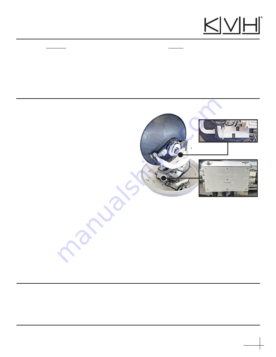
Figure 1:  V11-HTS Antenna Main Conversion Components

Summary of Contents for TracPhone V11

Page 1: ...es not have software version 209 0 or later installed it will not be able to communicate properly with the new ICM when you convert the system to V11 HTS TracPhone V11IP V11 to V11HTS Conversion Instructions Technical Support If you need technical assistance please contact KVH Technical Support Europe Middle East Africa Asia Pacific Phone 45 45 160 180 Email mvbsupport kvh com North South America ...

Page 2: ...he three hex latches securing one of the service hatches to the baseplate see Figure 2 Open the hatch NOTE If you are unable to work through the hatch you may remove the radome instead 3 Set the power switch inside the antenna to the Off position see Figure 3 NOTE If you are unable to see the power switch and cannot use the other hatch reach towards the Wi Fi antenna end of the connector module an...

Page 3: ... riser with twelve 3 8 cm pieces of the supplied Kapton tape applied in vertical evenly distributed bands around the feed tube see Figure 5 Center the pieces of tape at the seam between the shield and riser and smooth toward the ends If the feed tube riser is loose or dislodged contact KVH Technical Support The riser may need to be replaced Figure 4 Gray Tape Applied at the Factory Figure 5 Kapton...

Page 4: ... replace the LNB Antenna LNB Go to Legacy LNB 1 NOTE Since the filter is inside the original LNB being replaced an external filter is added to the LNB 3 page 5 LNB 1 with Filter Assembly NOTE An LNB 1 with filter assembly may be present if it was used to replace a failed original LNB page 6 LNB 1 without Filter NOTE Filter is inside the OMT page 7 ...

Page 5: ...and Figure 9 Tighten the screws to 21 in lbs of torque 5 Remove the protective cap from the LNB s RF connector Then connect the RF cable to the LNB making sure that the RF cable is aligned to prevent any interference when the feed assembly rotates see Figure 9 Tighten with a 7 16 torque wrench set to 15 in lbs 6 Secure the RF cable to the LNB using the tie wrap supplied in kit as shown in Figure 8...

Page 6: ...s shown in Figure 12 and Figure 13 Tighten the screws to 21 in lbs of torque 5 Remove the protective cap from the LNB s RF connector Then connect the RF cable to the LNB making sure that the RF cable is aligned to prevent any interference when the feed assembly rotates see Figure 12 Tighten with a 7 16 torque wrench set to 15 in lbs 6 Secure the RF cable to the LNB using the tie wrap supplied in k...

Page 7: ...LNB to the OMT see Figure 15 Remove the LNB 4 Using the 3mm hex key supplied in kit remove the four M4 screws securing the filter to the LNB 3 see Figure 16 Discard the filter 5 Make sure the rubber O ring is pressed into the groove of the LNB s mounting surface see Figure 17 Important Before removal note the LNB orientation the LNB notch shown in Figure 14 and Figure 15 faces the OMT and be sure ...

Page 8: ...ble to the LNB making sure that the RF cable is aligned to prevent any interference when the feed assembly rotates see Figure 18 Tighten with a 7 16 torque wrench set to 15 in lbs 8 Secure the RF cable to the LNB using the tie wrap supplied in kit as shown in Figure 18 and Figure 19 Trim the excess portion of the tie wrap and discard it 9 Continue to Replace the Power Thermal Module on page 9 Figu...

Page 9: ...TS Ready power thermal module to the frame Tighten the captive screws to 32 in lbs of torque 4 Reconnect the nine cables to the power thermal module Match the labels on the cables with the labels on the power thermal module When reconnecting the coax cables nos 7 9 in Figure 20 hold the base of the connector while tightening Tighten to 15 in lbs of torque When reconnecting the cables that have DB9...

Page 10: ... the antenna to make sure you have not left any tools or debris inside 7 Set the power switch inside the antenna back to the On position see Figure 22 8 Close the hatch and lock its three hex latches NOTE If the customer would like to replace the V11 or V11 IP decals on the radome new V11 HTS labels are available from KVH A complete V11 HTS radome is also available for purchase To order one of the...

Page 11: ...00 or NMEA 0183 HS standards 4 Be sure to perform all other steps in the installation guide that follow the initial ICM preparation mounting and wiring steps including the following Connect the ICM Jumper Cable see Figure 25 Attach the Wi Fi Antennas see Figure 25 Connect the RF Terminator see Figure 26 Then verify the overall wiring against the Wiring Diagram appendix Figure 23 V11 IP ICM Figure ...

Page 12: ...et 1 port on the rear panel of the ICM 3 Start PuTTY and enter the ICM s IP address and port number see Figure 27 Select Telnet for Connection type then select Open to start a Telnet session and open a command line window NOTE By default the ICM uses a gateway of 192 168 5 1 and port 50001 4 At the command line enter and send the following commands to the antenna HALT DEBUGON EEUNLOCK LNBTYPE 3 ZA...

Page 13: ... Support to commission the modem KVH will coordinate with the NOC to run a P1dB test to determine the 1 dB compression point of the BUC block up converter and the maximum transmit power Configure the Network Choose from the most common network configurations at the web interface or contact KVH Network Services for a custom configuration Refer to Understanding the Network Configuration Changes see ...

Reviews: