background image

1

1

Date:

17-12-2015

Machine type:

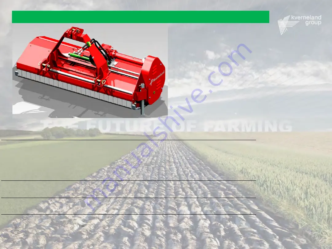
FHS- Bromex PM – SE 3000 Chopper : 1,55 - 1,85 – 2,00 - 2,30 – 2,50 m

Address:

Kverneland Group Modena S.p.A.

Strada Ponte Alto 74

41123 MODENA

Italy

Receiver:

Technical Service

Details:

Technical machine information, adjustments and failure finding

Serial number:

> serial number  MACHOXX105698 ( Produced on December 2015) 

Technical Service Manual          FHS Chopper 155-185-200-230-250

Released 2 by co_ali 17/12/2015

Summary of Contents for FHS 155

Page 1: ...roup Modena S p A Strada Ponte Alto 74 41123 MODENA Italy Receiver Technical Service Details Technical machine information adjustments and failure finding Serial number serial number MACHOXX105698 Produced on December 2015 Technical Service Manual FHS Chopper 155 185 200 230 250 Released 2 by co_ali 17 12 2015 ...

Page 2: ...be an HANDBOOK manual only for service purposes The use and maintenance manuals are primary concerning all the characteristic data If a inconsistency in data between service manuals and the use and maintenance manuals is find MAINTENANCE MANUALS DATA ARE PRIMARY ...

Page 3: ...nt safety guards 15 Adjusting skids and roller height 16 Replacing skid wearing plate 17 Replacing rotor 18 Replacing tools 26 Replacing belts 29 Belts tensioning 31 Rear cover 34 Replacing hydraulic cylinder 35 Adjusting rake tines 37 Maintenance and troubleshooting Follow Replacing gearbox 38 Cleaning 43 Greasing 44 Checking oil level 45 Attachment Oil and Grease Characteristics 47 Bolt tighteni...

Page 4: ...S 185 FHS 200 FHS 230 FHS 250 PTO Input speed RPM 540 Power Kw Input Kw 27 32 35 40 45 Maximum Kw 82 Rotor Speed RPM 2243 Rotor Shaft diam mm 50 Rotor diam mm 169 Universal Blades cutting diam mm 452 Universal Blades Tip speed m s 53 1 Hammer Blades cutting diam mm 447 Hammer Blades Tip speed m s 52 4 Rock Blades cutting diam mm 435 Rock Blades Tip speed m s 51 3 Model FHS 155 FHS 185 FHS 200 FHS ...

Page 5: ...5 General data and equipment Landmark Orientation 5 ...

Page 6: ...n Overall dimensions H 1 21 m D 0 95 m Road transport Transport Height H 500 mm Minimum H To avoid hits that could damage rear roller and other parts of the machine we suggest to keep the machine at minimum 500 mm from ground during the road transport ...

Page 7: ... Ch mm 40 42 5 48 5 Ch Ch Working position Intermediate position Universal Blades shown Tool Type Universal Blade Hammer Blade Rock Blade Cutting Diameter Cd mm 452 447 435 Cutting Height Ch mm 80 82 5 88 5 Ch Working position Higher Position Universal Blades shown Tool Type Universal Blade Hammer Blade Rock Blade Cutting Diameter Cd mm 452 447 435 Cutting Height Ch mm 120 122 5 128 5 ...

Page 8: ...stock Front safety Guards Frame FHS 185 shown Skids Offset Hydraulic Cylinder Hydraulic Hoses Offset Slide Guides Parking Stand Side Transmission Cover General data and equipment Standard equipment glossary 8 ...

Page 9: ...9 General data and equipment Standard equipment glossary 9 Rear cover Gearbox Roller Roller scraper Drive shaft guard Counterknife Kit ...

Page 10: ...10 Universal Blades Rotor 185 Rotor shown General data and equipment Working tools 10 Hammer Blades Rotor 185 Rotor shown Rock Blades Rotor 185 Rotor shown ...

Page 11: ...11 General data and equipment Optional equipment glossary 11 Rake tines rear cover Second Counterknife Kit ...

Page 12: ...Disassembly the lower Pins Hitch including the safety Pins and the Washers Insert the spherical joints then insert again the lower Pins hitch the Washers and the safety Pins 12 Lower pin hitch Safety pin and washer Spherical joint Final lower hitch assembly ...

Page 13: ...ing chopper to tractor Step 2 Approach the tractor to the chopper while is in parking position with the lower hitch arms lowered Lift up the lower hitch arms until are fully engaged on the spherical joints Lift up the parking stand ...

Page 14: ...nk pin including the safety pin and the washer Insert the top link bar then insert again the top link pin the washer and the safety pin Top link pin Top link bar Safety pin and washer Adjust the top link bar by rotating it until the top link pin is on the far side of the upper slot ...

Page 15: ...15 Getting started 15 Connecting chopper to tractor IMPORTANT NOTE Try to keep the horizontal position of the chopper during the work as shown in figure this is the most effective way to work with ...

Page 16: ...onnect safety pin and washer on the left side Extract the safety guards support pin Change the damaged safety guard Insert again the safety Guards support Pin and then insert the washer and the safety pin to lock it Safety guards support pin Safety guards Washer Safety pin ...

Page 17: ...ing position between the 3 choices See figures below Then assemble the rear screws and nuts in the chosen position and tighten them all Including the front ones Upper position 40 mm cutting height Intermediate position 80 mm cutting height Lower position 120 mm cutting height Front support screw and nut Rear support screws and nuts NOTE For further information concerning the cutting height see pag...

Page 18: ...ocking nuts on both sides then un assenble the countersunk head screws Then replace the wearing plates insert the countersunk Head Screws and fix it tightening the self locking Nuts NOTE To avoid unwanted side bending always replace simultaneously both the wearing plates Self Locking Nut Self locking nut Countersunk Head Screw Countersunk Head Screw Wearing plate Skid ...

Page 19: ...19 Maintenance and Troubleshooting 19 Replacing rotor Replacing rotor Step 1 Screw Washer Side transmission cover Remove the side transmission cover screws then remove the cover ...

Page 20: ...it screws until the lower pulley is free moving Remove both the lower clamp and the lower pulley Remove the belts 1 5 2 6 3 4 Clamping Unit tightening sequence IMPORTANT NOTE For a correct re assembly follow in reverse order the hereby steps for the lower clamp unit use the tightening sequence as shown in the lower left picture ...

Page 21: ... Remove the lower screws self locking nuts and the washers fixing the lower cover Screws Washers Self locking nuts Grower washer Lower cover Remove the side screws self locking nuts the washers the rotor screw and the grower washer Remove the lower cover Screw Use threadlocker LOCTITE Type 270 ...

Page 22: ...e and Troubleshooting 22 Replacing rotor Step 4 Screws Self locking Nuts Skids Roller Assembly Screw Self locking Nuts Remove the screws on both sides and the self locking nuts fixing the skids rear roller assembly ...

Page 23: ...or stand Chain Chain Hook NOTE During the Rotor disassembly use wood Blocks Or similar to support the rotor then use chains and hooks connected as shown to lift up the chopper The Rotor stand parts are represented only for graphical purposes consequently ARE NOT EXISTING PARTS ...

Page 24: ...g rotor Step 6 Grower Washers Screws Remove the seven screws and the grower washers on left side Use threadlocker LOCTITE Type 270 Grower Washers Remove the eight screws and the grower washers on right side Screws Use threadlocker LOCTITE Type 270 ...

Page 25: ...25 Maintenance and Troubleshooting 25 Replacing rotor Step 7 After loosing the side screws lift up the frame using chain and hooks until the rotor is completely un assembled ...

Page 26: ...eshooting 26 Replacing rotor Step 8 Circlip Shaft seal Circlip Ball Bearing Rotor support Body IMPORTANT NOTE During the rotor supports disassembly and re assembly ALWAYS use proper tools to avoid damages to shaft seals and ball bearings ALWAYS keep the parts clean and lightly greased ...

Page 27: ...eplacing tools replacing universal blades Remove the screw and the self locking nut Replace the damaged or worn out tool and then insert the screw again and tight the self locking nut IMPORTANT NOTE All the Rotors are factory balanced we suggest to replace all the Tools to keep the balance ...

Page 28: ... replacing hammer blades Remove the screw the self locking nut and the washers Replace the damaged or worn out tool and then insert the screw again the washers and tight the self locking nut IMPORTANT NOTE All the Rotors are factory balanced we suggest to replace all the Tools to keep the balance ...

Page 29: ...rew Self locking nut Rock blade Remove the screw and the self locking nut Replace the damaged or worn out tool and then insert the screw again and tight the self locking nut IMPORTANT NOTE All the Rotors are factory balanced we suggest to replace all the tools to keep the balance ...

Page 30: ...asher Side transmission cover During the normal use of the Machine User has to check the Belts status every 30 hrs of work After checking if needed replace the worn belt or belts IMPORTANT NOTE Do not replace individual belts replace all 5 belts at the same time ...

Page 31: ... all 5 belts at the same time Maintenance and Troubleshooting 31 Replacing belts Lower nut Upper nut Loosen the upper and the lower nut and the tensioner rod Loosen the upper nut until the tensioner pulley is completely detached from the belts Belt tensioner drum Automatic Belt Tensioner in working position Belts ...

Page 32: ...e replacing Belts please check the pulley and the Belt tensioner Drum positions as specified in the upper figures After replacing Belts screw upper Nut until the Belt Tensioner Drum is approx in the upper figure shown position Then lock the lower Nut to fix the Belt Tensioner in this position ...

Page 33: ...le of the belt approximately halfway between the two pulleys With one finger slowly and firmly press down on the push button When a click is heard stop pressing and gently remove the gauge Read the graduated scale on top of the gauge at the exact point where the indicator arm crosses the graduated scale Repeat the previous steps for each belt Tensioning value Typical tension values First installat...

Page 34: ...and still to avoid fake readings due to hand movement Hit the belt to make it vibrate Read drive belt frequency on the display Repeat the previous steps for each belt Typical frequency values First installation 86 Hz After testing running 72 Hz Digital display Frequency meter probe Digital frequency meter Digital frequency meter IMPORTANT NOTE Check the belt tension at the first 10 hours of workin...

Page 35: ...ce and Troubleshooting 35 Rear cover IMPORTANT NOTE NEVER USE OPEN REAR COVER DURING WORKING COULD BE DANGEROUS AND HARMFUL TO SURROUNDING PEOPLE Rear cover in working position Rear cover when cleaning the machine ...

Page 36: ...er Loosen the hydraulic nipples the hoses and the copper washers Hydraulic hoses Copper washer Hydraulic nipple Hexagonal head screw Washer Self locking nut Loosen the hexagonal head screw and the self locking nut remove them and the washer Offset hydraulic cylinder ...

Page 37: ...der Nut Hydraulic cylinder rod Loosen the nut inside the transmission cover then push backward the hydraulic cylinder rod and finally the hydraulic cylinder CAUTION Pushing the hydraulic cylinder rod in closed position could produce oil leakage from the inlet ports ...

Page 38: ...38 Maintenance and Troubleshooting 38 Adjusting rake tines ...

Page 39: ...39 Maintenance and Troubleshooting 39 Replacing gearbox Screw Washer Side transmission cover Remove the hexagonal head screws and the washers Disassembly the side transmission cover ...

Page 40: ...tening sequence Loosen the lower clamping unit screws until the lower pulley is free moving Remove both the lower clamp and the lower pulley Remove the belts IMPORTANT NOTE For a correct re assembly follow in reverse order the hereby steps for the lower clamp unit use the tightening sequence as shown in the lower left picture ...

Page 41: ... tightening sequence Loosen the upper clamping unit screws until the upper pulley is free moving Remove both the upper clamp and the upper pulley IMPORTANT NOTE For a correct re assembly follow in reverse order the hereby steps for the upper clamp unit use the tightening sequence as shown in the lower left picture ...

Page 42: ... is to hold the main shaft support in position and prevent unwanted vibrations Locking nut Fixing screw Loosen the fixing screw Loosen the locking nut Gearbox group Remove the whole gearbox and side shaft assembly Disassembly the screws and the grower washers Grower washer Screws Use threadlocker LOCTITE Type 270 ...

Page 43: ...43 Maintenance and Troubleshooting 43 Replacing gearbox Max 0 5 Max 0 5 During the gearbox group re assembly carefully check the axis slope both in vertical and horizontal direction See Figures ...

Page 44: ...isplacement of the Headstock Our suggestion is to check the movement daily and if is necessary to use a compressed air gun to remove dirt Be sure that the sliding guides are slightly greased if not use a brush to restore the greasing check it daily Critical points Critical points During normal use wet grass could stick up on the Roller this could bend the Roller Scraper and the Roller Supports Dai...

Page 45: ...Shown below there are the Greasing Points Rotor bearings greasing points Maintenance interval Every 50 Hrs Grease Quantity Approx 2 Pump strokes Roller bearings greasing points Maintenance interval Every 50 Hrs Grease Quantity Approx 1 Pump strokes ...

Page 46: ...id check and levels Gearbox assy IMPORTANT NOTE The machine must be stopped and placed in horizontal position before checking all the oil levels Gearbox unit Filling plug Drain plug Level plug Level plug Gearbox main Shaft Support Filling plug ...

Page 47: ...e lower edge of the hole Check oil level before each use To check the Gearbox main Shaft support Oil level loose the level Port Plug the Oil level should reach the lower edge of the Hole If necessary top up the Oil level To load Oil in the Gearbox main Shaft support loose the level port Plug then loose the loading port Plug and fill up the main Shaft support until the Oil level reach the lower edg...

Page 48: ... Gears Exposed Gears General Grease Type Grade NLGI 2 Description Multipurpose Grease Specifications DIN 51825 KP Approvals K2K 20 Applications Roller Bearings Plain Bearings General lubrication IMPORTANT NOTE Do not mix Oils of different types and specifications this could cause malfuncitons and serious damages to items IMPORTANT NOTE Do not mix Greases of different types and specifications and d...

Page 49: ...iam M6 507 902 1270 1520 0 58 1 03 1 46 1 75 M8 920 1640 2310 2770 1 39 2 48 3 49 4 19 M10 1480 2600 3660 4380 2 83 4 97 7 8 37 M12 2120 3780 5320 6380 4 74 8 46 11 9 14 3 M14 2890 5160 7250 8700 7 54 13 46 18 92 22 7 M16 3950 7020 9900 11900 11 5 20 4 28 8 34 6 M18 4840 8600 12100 14500 16 28 4 40 48 M20 6160 11000 15450 18500 22 2 39 6 55 6 66 6 M22 7630 13600 19100 22900 30 53 74 5 90 ...

Page 50: ...0 9 12 9 6 6 8 8 10 9 12 9 Nominal bolt diam M8x1 995 1750 2470 2960 1 48 2 6 3 7 4 4 M10x1 25 1540 2740 3860 4630 2 9 5 2 7 3 8 7 M12x1 25 2420 4140 5800 6980 5 3 9 1 12 8 15 4 M12x1 5 2220 3960 5570 6680 5 8 9 12 5 15 M14x1 5 3150 5600 7880 9450 8 14 3 20 24 M16x1 5 4200 7500 10500 12600 12 21 5 30 36 M18x1 5 5430 9700 13600 16300 17 4 31 43 52 ...

Page 51: ...51 Gearbox MAG636 Comer Service manual 51 ...

Page 52: ...52 1 Disassembly 52 ...

Page 53: ...53 2 Assembly B 53 ...

Page 54: ...54 3 Technical specifications 54 ...

Reviews: