Komfovent VERSO-P, Installation And Maintenance Service Manual
The Komfovent VERSO-P, a state-of-the-art ventilation system, offers exceptional indoor air quality. Ensure proper installation and maintenance with our comprehensive "Installation and Maintenance Service Manual". Download the manual for free from manualshive.com, providing insightful guidelines and instructions for maximizing the performance and longevity of your Komfovent VERSO-P.
Share
Download


Reviews:
No comments
Related manuals for VERSO-P

12-521
Brand: Radio Shack Pages: 1

HG50.25.V2
Brand: Sealey Pages: 5

22-4 HD PVMV-N
Brand: Fischer Panda Pages: 154

SDMO DIESEL 4000 C5
Brand: Kohler Pages: 222

040234-1
Brand: Briggs & Stratton Pages: 7
TFT-720
Brand: LENCO Pages: 31

LR-400
Brand: Listen Technologies Pages: 2

TX-G10/C
Brand: Panasonic Pages: 14

TX-G10/C
Brand: Panasonic Pages: 30
RP-444
Brand: Sanyo Pages: 8
DVD-L77
Brand: Sanyo Pages: 15
DVD-HP62
Brand: Sanyo Pages: 20

DVD-HP42
Brand: Sanyo Pages: 19
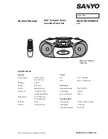
MCD-DV595M/XE
Brand: Sanyo Pages: 22
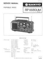
RP 8880UM
Brand: Sanyo Pages: 35
Standby Generators
Brand: Siemens Pages: 16

Liquid-cooled Generators
Brand: Siemens Pages: 24

1D Series
Brand: Siemens Pages: 45


