HEALTH IMAGING
© Eastman Kodak Company
Publication No. XP3210-006
18JUL97
Repairing the
LASER PRINTER KEYPAD
a component of the
3230 Kodak Ektascan 2180 LASER PRINTER,
3226 Kodak Ektascan 1120 LASER PRINTER,
3210 Kodak Ektascan LASER PRINTER
Model 100 XLP,
3222 Kodak Ektascan LASER PRINTER
Model 100 XLP Upgrade,
3140 Kodak Ektascan IMAGE MANAGER
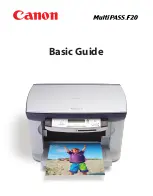
Purpose:
Use this procedure to repair only the KEYPAD with the tilting MESSAGE DISPLAY, identified by
the figure below.
Order a replacement KEYPAD only if the KEYPAD cannot be repaired.
H027_2527AA