


BAC-9300 Series Controller
Installation Guide
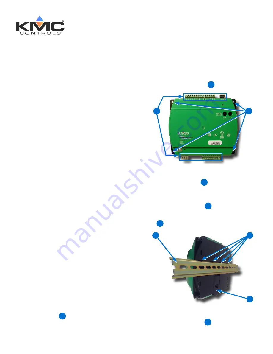
NOTE:
The black terminals are for power. The
green terminals are for inputs and
outputs. The gray terminals are for
communication.
2. Screw a #6 sheet metal screw through each
corner of the
controller
2
.
1
2
On a DIN Rail
1. Position the
DIN rail
3
so that when the
controller is installed the color-coded terminal
blocks are easy to access for wiring.
2. Pull out the
DIN Latch
4
until it clicks once.
3. Position the controller so that the top
four tabs
5
of the back channel rest on the DIN rail.
4
5
3
4. Lower the controller against the DIN rail.
5. Push in the
DIN Latch
6
to engage the DIN
rail.
INTRODUCTION
Complete the following steps to install a KMC
Conquest™ BAC-9300 Series Unitary Controller.
For controller specifications, see the
data sheet
at
kmccontrols.com
. For additional information, see
the
KMC Conquest Controller Application Guide
.
MOUNT CONTROLLER
NOTE:
Mount the controller inside a metal
enclosure for RF shielding and physical
protection.
NOTE:
To mount the controller with
screws
on
a flat surface, complete the steps in
On
a Flat Surface on page 1
. Or to mount
the controller on a 35 mm
DIN rail
(such as integrated in an
HCO-1103
enclosure), complete the steps in
On a
DIN Rail on page 1
.
On a Flat Surface
1. Position the controller so the color-coded
terminal blocks
1
are easy to access for
wiring.
KMC Controls, 19476 Industrial Drive, New Paris, IN 46553
/
877.444.5622
/
Fax: 574.831.5252
/
www.kmccontrols.com
CONTENTS
Introduction .............................................. 1
Mount Controller ........................................ 1
Connect Sensors and Equipment .................. 2
Connect (Opt.) Pressure Flow Sensor ............ 3
Connect (Opt.) Ethernet Network .................. 3
Connect (Optional) MS/TP Network............... 4
Connect Power .......................................... 4
Power and Communication Status ................. 4
MS/TP Network Isolation Bulbs .................... 5
Configure/Program the Controller
................. 6
Sample (BAC-9311) Wiring
.......................... 7
Input/Output Objects/Connections ................ 8
Replacement Parts ....................................10
Important Notices .....................................10


