background image


A

bso Charger 


12V 20A 

(AC1220) 

12V 40A 

(AC1240) 

12V 60A 

(AC1260) 

24V 30A 

(AC2430)


Owner’s Manual 


Summary of Contents for Abso Charger 12V 20A

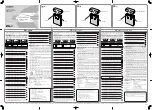
Page 1: ...Abso Charger 12V 20A AC1220 12V 40A AC1240 12V 60A AC1260 24V 30A AC2430 Owner s Manual ...

Page 2: ...echnology assumes no responsibility for errors or omissions Note as well that specifications and product functionality may change without notice Important Please be sure to read and save the entire manual before using your KISAE Abso Charger Misuse may result in damage to the unit and or cause harm or serious injury Product Numbers AC1220 Abso Charger 20A AC1240 Abso Charger 40A AC1260 Abso Charge...

Page 3: ...e 3 Table of Contents 1 INTRODUCTION 4 2 PRODUCT DESCRIPTION 5 3 UNDERSTANDING THE UNIT 5 4 INSTALLING THE CHARGER 9 5 UNIT OPERATION 12 6 SPECIFICATIONS 17 7 WARRANTY 18 Appendix A1 Appendix A2 Appendix B ...

Page 4: ...hand in the event battery acid comes in contact with eyes If this occurs cleanse right away with soap and water for a minimum of 15 minutes and seek medical attention Batteries produce explosive gases DO NOT smoke or have an open spark or fire near the system Keep unit away from moist or damp areas Never expose unit to snow water etc Avoid dropping any metal tool or object on the battery Doing so ...

Page 5: ...ng AC1220 20A 12V AC1240 40A 12V 12V Model AC1260 60A 12V 24V Model AC2430 30A 24V 3 UNDERSTANDING THE UNIT The KISAE Abso Charger is a fully automatic multistage battery charger with the ability to charge 3 separate battery banks When first connected to an AC power source the charger will check all three battery banks before charging commences The charger operates on an isolated charging design w...

Page 6: ...rfect fast and accurate charging This charger delivers four primary charge stages Bulk Charge Absorption Charge Float and Maintenance Bulk Charge The battery is charged at full rated output current of the charger until the battery reaches the final charging voltage known as its absorption voltage In this step around 80 of the battery is recovered as fast as possible Absorption Charge With the char...

Page 7: ...n to float stage current L current in A GEL AGM Flooded battery type only The charger can also be set to Power Supply Mode Program setting on CH 1 With this setting the charger will only provide constant voltage and current to Battery Bank 1 CH 1 only Battery Bank 2 and 3 CH 2 3 are disabled Even with battery banks are connected to the two banks no DC voltage or current will be supplied to these t...

Page 8: ...Manufacturing default setting is set to Normal temperature See more details on Understanding the Battery Temperature Function in Section 5 Digital Display CH1 CH2 and CH3 represent Battery Bank 1 2 and 3 respectively With CH1 turned on the numerical value on the display shows individual battery information like battery voltage in V or charging current in A CH 2 and CH 3 will always turn on togethe...

Page 9: ...re beginning your unit Installation please consider the following The unit should be used or stored in an indoor area away from direct sunlight heat moisture or conductive contaminants When placing the unit allow a minimum of three inches of space around the unit for optimal ventilation Note The charger is designed to be permanently mounted Mounting the Charger Choose an appropriate mounting locat...

Page 10: ... secure the cover using the two screws provided AC Input Wiring WARNING The AC wiring must be of appropriate size and it must be protected by an appropriate branch breaker not provided connected between the AC source and the charger A three color coded 14 AWG wire L N and GND with a rated minimum of 75 C wire and a minimum 12 inches in length must be used Before connecting AC wiring make sure the ...

Page 11: ...to be done through the Remote Display Before connecting the batteries to the chargers Battery Bank 1 of Charger_1 has to connect to Battery Bank 1 of Charger_2 Battery Bank 2 of Charger_1 has to connect to Battery Bank 2 of Charger_2 and Battery Bank 3 of Charger_1 has to connect to Battery Bank 3 of Charger 2 The Common Ground of both chargers has to be connected together Damage to both chargers ...

Page 12: ...g the float stage charging stage each battery bank is separate by an internal separation diode In float stage see the below chart for the maximum allowable current draw AC 1260 AC 1240 AC 1220 AC 2430 Maximum Float Current 40A 40A 20A 20A For charging GEL AGM and Flooded batteries The charger can be set to Mode 2 2 stage charging Bulk and Absorption stage charging only no float stage or Mode 3 3 s...

Page 13: ...rstanding the Two Stage Mode 2 Charging The Two Stage charging is similar to the Three Stage charging except there is no float stage after the absorption stage The charger will terminate the battery charging after Absorption The charger will automatically restart the full charging cycle if it senses anyone of the battery bank is discharged to lower than 12 5V for 12V model 25 0V for 24V model or a...

Page 14: ... are required for setting Charging Voltage 13 9 14 4V for 12V model and 27 8 28 8V for 24V model Maximum Charging Current see table below Termination Charging Current current to define when the charging process will terminate The following table shows the available charging voltage maximum charging current and the available termination charging current Model Charging Voltage Maximum Charging Curre...

Page 15: ...ld have similar electrolyte levels If distilled water is added batteries must undergo a complete charge cycle The charger cannot determine when to terminate the equalization of the battery A one hour time out is set and this is used as a safety feature to require the user to continually re activate it as necessary after checking batteries manually During equalization mode the other two banks are d...

Page 16: ...01 Unit shutdown due to low AC Input 85 5Vac Check AC input source The unit will automatically recover when the AC Input voltage return to 108 5Vac E02 Unit shutdown due to high AC Input 270 5Vac Check AC input source The unit will automatically recover when the AC Input voltage return to 260 5Vac E03 Battery is connected backwards Check all battery connections E04 Charger Internal temperature is ...

Page 17: ... DC Output Connection AC Input Connection Hardwire or AC Cord DC Output Connection POS Heavy Duty Studs 3 banks DC Output Grounding NEG Single Heavy Duty Common Ground Stud Environmental and Operating Temperature Storage Range 40 to 70 C 40 to 158 F Operating Range 20 to 60 C 4 to 140 F Humidity 5 95 RH non condensing Ingress Protection IP32 Based Unit Weight and Dimensions AC1220 5 3 lb 11 6 x 8 ...

Page 18: ...tail store After speaking to a customer service representative if products are deemed non working or malfunctioning the product may be returned to the purchasing store within 30 days of original purchase Any defective unit that is returned to manufacturer within 30 days of the date of purchase will be replaced free of charge If such a unit is returned more than 30 days but less than one year from ...

Page 19: ...Page 19 ...

Page 20: ...Page 20 ...

Page 21: ...Page 21 Appendix B ...

Reviews: