background image

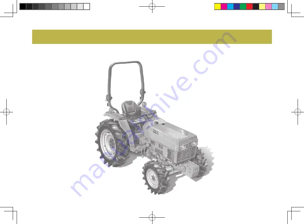
Congratulations, and welcome to the fabulous world of 

LK30/LK35

 ownership, where serious work is made 

fun again! 

This versatile tractor is a culmination of the entire tractor and diesel knowledge gained by the Daedong In-

dustrial Co.,LTD since 1947.  It has been designed with the finest materials and under rigid quality control 

standards  set forth by the 

KIOTI

 Engineering Department.

Knowledge  of  tractor  operation  is  essential  for  many  years  of  dependable  service  and  reliability.  To  help 

new owner’s familiarize themselves with the 

KIOTI LK30/LK35

, it is the policy of 

KIOTI

 tractor to provide an 

owner’s manual which includes helpful information about tractor safety, operation and maintenance. If the 

information you seek is not found in this manual, your 

KIOTI

 tractor dealer will be happy to help you. 

Please feel free to contact 

DAEDONG IND. CO.,LTD

 with your questions/concerns. 

FOREWORD

LK35-AU-00.indd   1

2010-01-20   오후 2:58:34

Summary of Contents for LK30

Page 1: ...ineering Department Knowledge of tractor operation is essential for many years of dependable service and reliability To help new owner s familiarize themselves with the KIOTI LK30 LK35 it is the polic...

Page 2: ...n damage to your vehicle or its equipment if the caution is not heeded Follow the advice provided with the caution This indicates that a condition may result in harm serious in jury or death to you or...

Page 3: ...s USA American Society of Testing and Materials USA Feet Per Minute High Speed Low Speed Hydrostatic Transmission Meters Per Second Power Take Off Right hand and Left hand sides are determined by faci...

Page 4: ...LK35 AU 00 indd 4 2010 01 20 2 58 34...

Page 5: ...re Turn Signal Power Take Off Clutch Con trol On Position Power Take Off Clutch Con trol Off Position Differential Lock Position Control Lowered Position Hazard Warning Lights Headlight Low Beam Headl...

Page 6: ...LK35 AU 00 indd 6 2010 01 20 2 59 22...

Page 7: ...TOR SPECIFICATIONS DESCRIPTION OF OPERATING SYSTEM OPERATION THREE POINT HITCH DRAWBAR HYDRAULIC UNIT TIRES TREAD AND BALLAST MAINTENANCE PERIODIC SERVICE STORAGE TROUBLESHOOTING OPTIONS INDEX 1 2 3 4...

Page 8: ...LK35 AU 00 indd 8 2010 01 20 2 58 43...

Page 9: ...OPERATING THE TRACTOR 1 5 DRIVING THE TRACTOR 1 8 PARKING THE TRACTOR 1 9 OPERATING THE P T O 1 10 USING 3 POINT HITCH 1 10 SERVICING THE TRACTOR 1 11 TRACTOR SAFETY LABELS 1 14 SAFETY PRECAUTIONS 1 L...

Page 10: ...tarting the tractor make sure your path is clear of people to avoid accidents caused by sudden move ments 8 Before making reverse movements with your tractor you should always check to see that the pa...

Page 11: ...or unless a passenger seat is installed Keep bystand ers away from the tractor while in operation 14 When getting on and off the trac tor handholds and step plates should always be used This will help...

Page 12: ...n should be taken when driving tractors with nar row tread widths For added sta bility you should adjust your rear wheel tread width see page 8 3 19 Before starting your tractor you should depress the...

Page 13: ...injury 2 Do not park your tractor on a steep incline and remember to shut off the engine and P T O before dis mounting the tractor OPERATING THE TRACTOR 3 Do not operate your tractor in an enclosed bu...

Page 14: ...only from the drawbar Never hitch anything to the axle housing or any other point except the draw bar Pulling from any other location only increase the risk of serious per sonal injury or death 6 If T...

Page 15: ...r operation 15 When working in groups always let the others know what you are going to do before you do it 16 Never freewheel Disengaging the clutch or shifting into neutral while descending a slope a...

Page 16: ...e Use hazard lights as required 1 Lock the brake pedals togeth er when traveling at road speeds Brake both wheels simultaneously when making an emergency stop Uneven braking at road speeds could cause...

Page 17: ...teering wheel as this can cause a loss of control of the tractor This risk is especially great when traveling at road speeds 9 Do not operate an implement while the tractor is on the road Lock the thr...

Page 18: ...using a 3 point hitch mount ed implement be sure to install the proper counterbalance weight on the front of the tractor 3 When transporting on the road set the implement lowering control in the LOCK...

Page 19: ...shift lever in neutral and stop the engine 1 Do not smoke while working around the battery or when refueling your tractor Keep all sparks and flames away for the battery and fuel tank The battery pre...

Page 20: ...ned to the specified torque 13 Escaping hydraulic fluid under pressure has sufficient force to penetrate skin causing serious personal injury Be sure to release all residual pressure Before dis connec...

Page 21: ...ecommended If injured by escaping fluid see a medical doctor at once This flu id can produce gangrene and or severe allergic reaction 15 Keep environmental pollution in mind When replacing coolant dis...

Page 22: ...1 14 LK30 LK35 S41O131a TRACTOR SAFETY LABELS LK35 AU 01 indd 14 2010 01 20 3 02 55...

Page 23: ...rter terminals Machine may start in gear and move if normal starting circuitry is bypassed Start engine only from operator s seat with transmission and PTO in neutral Never start engine while standing...

Page 24: ...his tractor with the ROPS in the down position the chance for serious injury or death is increased Notice Only operate this tractor with ROPS in the down position when necessary Injury may result from...

Page 25: ...2 servicing 2 2 SERVICING OF TRACTOR 2 LK35 AU 02 indd 1 2010 01 20 3 07 09...

Page 26: ...the tractor and engine serial numbers The tractor serial number is located on the on the left side of the tractor The engine serial number is located on the right side of the engine crank case The tr...

Page 27: ...3 SPECIFICATIONS 3 2 TRAVELING SPEED 3 5 IMPLEMENT LIMITATION 3 6 SPECIFICATIONS 3 LK35 AU 03 indd 1 2010 01 20 3 10 08...

Page 28: ...4 5 8 1 53 7 8 2 06 24 6 34 4 5 1 19 Gross Engine Power HP kW rpm mm in cc cu in rpm U S gal U S gal U S gal U S gal U S gal Engine Capacities Model Type Number of Cylinder Bore and stroke Total disp...

Page 29: ...se speed Wet disc type Connected with the traveling brake Standard Position control Main pump 29 9 7 88 Power steering pump 16 2 4 26 Category I Overall length with 3p Overall length with3p frontweigh...

Page 30: ...2 238 Standard 1valve Double acting valve AU Option 1valve Double acting valve USA Live 540 2 600 1 000 2 600 2 800 110 2 Draw Bar clevis 1 349 2 974 1 36 18 8 1 84 11 68 1 24 17 78 0 77 11 04 kg lbs...

Page 31: ...1 89 1 17 2 68 1 66 4 32 2 68 6 34 3 93 8 79 5 46 12 49 7 76 18 8 11 68 1 24 0 77 1 72 1 06 2 44 1 51 3 96 2 46 5 78 3 59 8 02 4 98 11 39 7 07 17 78 11 04 LK30 LK35 LK30 LK35 1 31 0 81 1 82 1 13 2 58...

Page 32: ...OTE Implement size may vary depending on soil types and field conditions Lifting Capacity max loading weight The max allowable load which can be put on the 24 in aft of hitch W0 Implement weight The i...

Page 33: ...Tiller Box Blade Rear Blade Rotary Cutter Belt Guard Chain Guard Bale Transport Core Aerator Remarks Max Bucket width mm in Max Diging depth mm ft in Max Cutting width mm in Max Cutting width mm in M...

Page 34: ...MEMO MEMO LK35 AU 03 indd 8 2010 01 20 3 10 11...

Page 35: ...4 exterior view 4 2 Instrument Panel AND SWITCHes 4 4 foot and Hand Controls 4 5 DeSCRIPTION OF OPERATING SYSTEM 4 LK35 AU 04 indd 1 2010 01 20 3 11 17...

Page 36: ...4 LK30 LK35 4 LK30 LK35 exterior view 1 Seat 2 Steering Wheel 3 Fuel Cap Cover 4 Hood Bonnet 5 Head Light 6 ROPS 7 Turn Signal Lamp 8 Fender S41O401a LK35 AU 04 indd 2 2010 01 20 3 11 18...

Page 37: ...ERATING SYSTEM 4 DESCRIPTION OF OPERATING SYSTEM 1 Turn Signal Lamp 2 Top Link 3 Transmission Oil Inlet Tube 4 Lifting Rod 5 PTO Shield 6 Lower Link 7 Draw Bar 8 Check Chain S41O402a LK35 AU 04 indd 3...

Page 38: ...mp Gauge 4 Main Shift Lever 5 Left Turn Indicator 6 Right Turn Indicator 7 Hand Throttle Lever 8 Head Light Switch 9 Turn Signal Switch 10 Hazard Lamp Switch 11 Key Switch 12 Horn Switch Instrument Pa...

Page 39: ...h Pedal 2 Brake Pedal L 3 Brake Pedal R 4 Transmission Oil Inlet Cap 5 Foot Throttle Pedal 6 Hi Lo Shift Lever 7 PTO Shift Lever 8 Front Wheel Drive Lever 9 Parking Brake Lever 10 Differential Lock Pe...

Page 40: ...MEMO MEMO LK35 AU 04 indd 6 2010 01 20 3 11 25...

Page 41: ...5 Pre operation 5 2 OPERATING NEW TRACTOR 5 3 OPERATING THE ENGINE 5 4 OPERATING THE TRACTOR 5 11 OPERATION 5 LK35 AU 05 indd 1 2010 01 20 3 12 31...

Page 42: ...el See daily check in the pe riodic service section Check all danger and warning la bels Pre operation Daily check It is a good practice to know the con dition of your tractor before you start it You...

Page 43: ...ing precautions should be observed You should not operate your tractor at full speed for the first fifty hours of use Avoid sudden starts and stops In cold climates allow your tractor plenty of time t...

Page 44: ...red when operation your tractor inside a building or enclosed area Remember that exhaust fumes can be deadly Never start your tractors en gine while standing on the ground This can prevent un expected...

Page 45: ...GED N NEUTRALPOSITION LOW SPEED Main Gear Shift Lever Hi LO Gear Shift Lever The main gear shift lever pattern is in the form of an H The hi lo gear shift lever moves two stages high and low By combin...

Page 46: ...N Maintain it until the pre heat lamp is turned off ap prox 8 sec 5 Move the position control lever forward To lower implement move the posi tion control lever forward 1 Position Control Lever A DOWN...

Page 47: ...in the combustion chamber S41O507a 1 Clutch Pedal 7 Depress the clutch pedal 8 Turn the key to START po sition and release when the engine starts Because of the safety device the engine may not be st...

Page 48: ...lso comes on when the key is turned ON to preheat the engine and goes off au tomatically when preheat is com pleted If the lamp is still on immediately stop the engine and determine the cause S41O508a...

Page 49: ...gine start up This in turn can result in trouble in the hydraulic system To prevent the above observe the fol lowing instructions Warm up the engine at about 50 of rated rpm according to the table be...

Page 50: ...art the tractor Locate the good battery in a safe place where the jumper ca bles will reach 2 Engage the parking brake of the tractor and shift the transmission gear to neutral position 3 Put on safet...

Page 51: ...seat belt is auto locking retractable type 3 Seat Belt To avoid personal injury Make sure that the seat is completely secured after each adjustment Do not allow any person oth er than the driver to ri...

Page 52: ...switch is pulled out the hazard lights flash along with the indicator on the instrument pan el Push the switch in to turn off the light 2 Turn Signal Light Switch To indicate a right turn toggle right...

Page 53: ...dals have equal adjustment when using locked to gether 1 BRAKE PEDAL RIGHTAND LEFT 4 Raise the implement The clutch is disengaged when the clutch pedal is fully pressed down 5 Depress the clutch pedal...

Page 54: ...IGH LOW S41O518A F FORWARD R REVERSE To help prevent premature clutch wear The clutch pedal must be en gaged slowly and disengaged quickly Do not rest your foot on the clutch pedal Select the proper g...

Page 55: ...e Lever Engaged Disengaged S41O519A 3 RangeGearShift Lever Hi Lo The range gear shift can only be shift ed when tractor is completely stopped and clutch is depressed If it is difficult to shift the ra...

Page 56: ...while travel ing at road speeds This can cause your tractor to stop quickly and unexpectedly CAUTION Depress the clutch pedal before engaging the front wheel drive lever Tires will wear quickly if fro...

Page 57: ...Depress the clutch and brake ped al 3 After the tractor has stopped dis engage the P T O lower the imple ment shift the transmission into neutral release the clutch pedal and set the parking brake Sto...

Page 58: ...erature Gauge The engine suddenly slows or ac celerates Unusual noises are heard Exhaust fumes become dark While driving make the previous checks to ensure that all parts are functioning properly 4 En...

Page 59: ...cause Never operate the tractor while warn ing lamps are on INSTRUMENT CLUSTER S41O524A 1 Fuel Gauge 2 Tachometer 3 Coolant Temperature Gauge 4 Left Turn Indicator 5 Glow Plug Indicator 6 Engine Oil P...

Page 60: ...ts the hours that the tractor has been operated When the key switch is on the fuel gauge indicates the fuel level Be careful not to empty the fuel tank Otherwise air may enter the fuel sys tem Should...

Page 61: ...nd check the engine oil level Engine oil pressure warn ing lamp If the generator is not charging the warning lamp in the Easy Checker will come on Battery charging warning lamp S41O528a S41O529a S41O5...

Page 62: ...ore leaving the tractor seat When parking the vehicle on a hill position the shift lever at low forward 1st gear for uphill and low reverse 1st gear for downhill Set the parking brake and chock the wh...

Page 63: ...TECHNIQUES Differential Lock 1 Differential Lock Pedal A Press to ENGAGE B Release to DISENGAGE S41O535A To prevent damage to the parking brake lever make sure that brake pedals are ful ly depressed b...

Page 64: ...veling on road with 3 point hitch mounted implement attached be sure to have suffi cient front weight on the tractor to maintain steering ability CAUTION To avoid personal injury Always back up when g...

Page 65: ...eeds 1 Be sure that the wheels are adjust ed to provide the maximum stabili ty possible 2 You should slow down for rough roads slope and sharp turns This is especially important when you are transport...

Page 66: ...the clutch pedal down completely to stop the tractor move ment and any P T O driven equip ment movement before shifting the P T O gear shift lever To avoid shock loads to the P T O reduce engine spee...

Page 67: ...6 THREE POINT HITCH DRAWBAR 6 2 3 POINT HITCH 6 3 DRAWBAR 6 4 THREE POINT HITCH DRAWBAR 6 LK35 AU 06 indd 1 2010 01 20 3 14 08...

Page 68: ...6 LK30 LK35 6 LK30 LK35 1 Top Link 2 Lifting Rod Left 3 Lifting Rod Right 4 Lower Link 5 Drawbar 6 Check Link THREE POINT HITCH DRAWBAR S41O601a LK35 AU 06 indd 2 2010 01 20 3 14 10...

Page 69: ...ne from between an implement and tractor while its job being performed Attaching detaching work of implements must be done in a flat and safe place and a right lighting apparatus should be taken at ni...

Page 70: ...a S41O603a Adjust the check chain so that the implement can move 5 to 6 cm 2 0 to 2 4 in laterally Check chain shouid be tight enough to prevent excessive implement move ment when implement is in rais...

Page 71: ...7 3 POINT HITCH CONTROL SYSTEM 7 2 AUXILIARY HYDRAULICS 7 3 HYDRAULIC UNIT 7 LK35 AU 07 indd 1 2010 01 20 3 15 11...

Page 72: ...ple ment is stopped If the 3 point hitch can not be raised by setting the hydraulic control lever to the UP position after long term storage or when changing the transmission oil fol lowtheseairbleedi...

Page 73: ...he 3 point lowering speed knob 1 3 Point Lowering Speed Knob A FAST B SLOW C LOCK 3 point Hitch Lowering Speed t46O703a t46O702a AUXILIARY VALVE HYDRAULIC RELIEF VALVE 1 To the Tank 2 Relief Valve 3 T...

Page 74: ...ressure to system be sure all connections are tight and that lines pipes and hos es are not damaged Fluid escaping from a very small hole can be almost invisible Use a piece of cardboard or wood rathe...

Page 75: ...In Push In Out Port A B Lever Pressure Returning Move the lever up or down and hold This will raise or lower the implement Lever will return to neutral when re leased Port A B Coupler Size PT 1 2 Do...

Page 76: ...MEMO MEMO LK35 AU 07 indd 6 2010 01 20 3 15 15...

Page 77: ...8 TIRES 8 2 TREAD 8 3 BALLAST 8 5 TIRES TREAD AND BALLAST 8 LK35 AU 08 indd 1 2010 01 20 3 16 31...

Page 78: ...345kPa 3 5kgf cm2 50psi AG Turf Industrial AG Turf Industrial To avoid personal injury Do not attempt to mount a tire This should be done by a qualified person with the proper equipment Always maintai...

Page 79: ...tread Front Wheels Model Tire sizes t46O801b A Thread Tread LK30 LK35 7 14 6PR 27 8 5 15 6PR 25 8 5 14 4PR AG Turf Industrial 1 105 43 5 1 126 44 3 1 146 45 1 mm in Do not turn front discs to ob tain...

Page 80: ...PR 15 19 5 6PR 1 134 44 7 Always attach tires as shown in the drawings If not attached as illustrated transmission parts may be damaged When re fitting or adjusting a wheel tighten the bolts to the fo...

Page 81: ...rs bumper You should consult your implement own er s manual for the required amount of weight or contact your local KIOTI dealer for a recommendation Rear Ballast BALLAST option front ballast 1 Front...

Page 82: ...MEMO MEMO LK35 AU 08 indd 6 2010 01 20 3 16 35...

Page 83: ...9 SERVICE INTERVALS 9 2 LUBRICANTS 9 4 MAINTENANCE 9 LK35 AU 09 indd 1 2010 01 20 3 17 46...

Page 84: ...10 14 10 17 10 16 10 22 10 15 10 21 10 19 10 17 10 9 10 22 10 20 10 24 10 20 10 24 SINCE THEN Every100Hr Every200Hr Every200Hr Every400Hr Every400Hr Every50Hr Every50Hr Every50Hr Every100Hr Every100Hr...

Page 85: ...rvice as required 50 100 Check Replace Adjust Adjust Flush Change Bleed Drain Replace Replace Fuel line Toe in Engine valve clearance Cooling system Coolant Fuel system Clutch housing water Fuse Light...

Page 86: ...amage use only genuine KIOTI fluids oils and greases or equivalents Moderate amount 28 7 40 7 8 2 06 5 8 1 53 24 6 34 4 5 1 19 u s gal SAE30 SAE10W 30 or 10W 40 SAE20 SAE10W 30 or 10W 40 SAE10W SAE10W...

Page 87: ...RS 10 8 EVERY 50 HOURS 10 13 Every 100 hours 10 14 Every 200 hours 10 19 every 400 hours 10 21 Every 600 hours 10 22 Every 800 hours 10 22 Every 1 year 10 22 Every 2 years 10 23 service as required 10...

Page 88: ...hood It is not necessary to remove the side cover to perform daily checks on your tractor S41Oa01A S41Oa02A S41Oa03A To avoid personal injury from contact with moving parts Never open the hood or eng...

Page 89: ...it out again Check to see that the oil level lies between the two notches If the level is too low add new oil to the prescribed level at the oil inlet See LUBRICANTS in Mainte nance Section Checking E...

Page 90: ...Fuel tank capacity 28 7 4 U S gals S41Oa05A S41Oa06A If oil level is low do not run engine IMPORTANT To avoid personal injury Do not smoke while refueling Be sure to stop the engine before refueling...

Page 91: ...or mm2 s at 40 C Min 1 9 Max 4 1 Viscosity Saybolt SUS at 100 F Min 32 6 Max 40 1 sulfur weight Max 0 50 Copper Strip Corrosion Max No 3 Cetane Num ber Min 40 Flash Point C F Water and Sediment volum...

Page 92: ...nti freeze and water in the specified mixing ra tio up to the full level See Flush Cooling System and Changing Coolant in every 2 years maintenance 1 Recovery Tank A FULL B LOW S41Oa07A To avoid perso...

Page 93: ...eplace if broken Checking Seat Belt and ROPS 1 Always check condition of seat belt and ROPS attaching hardware be fore operating tractor 2 Replace if damaged Checking Gauges Meter and warning lamps 1...

Page 94: ...new oil up to the upper notch on the dipstick 1 Oil Inlet 2 Dipstick A Oil level is acceptable within this range 1 Drain Plug S41Oa09A S41Oa10A 1 Engine Oil Filter Replacing Engine Oil Filter S41Oa11...

Page 95: ...Pedal 1 Release the parking brake 2 Slightly depress the pedals and measure the free travel at the top of the pedal stroke 3 When adjustments are needed loosen the locking nut and turn the turnbuckle...

Page 96: ...Then tighten the filter by hand an addi tional half turn only 5 After the new filter is in place fill the transmission up with oil to the up per line of the oil gauge 6 After running the engine for a...

Page 97: ...top it and check the oil level again add oil to prescribed level 5 Check drain plugs for leaking Changing Transmission Fluid S41Oa15A S41Oa16A 1 Oil Inlet Plug 2 Gauge A Oil level is acceptable within...

Page 98: ...l the drain plugs 3 Remove the oil level check plug 4 Fill with the new oil up to the check plug port See LUBRICANTS in Maintenance Section 5 After filling reinstall the filling plug and check plug 6...

Page 99: ...tor is operated in extremely wet muddy or dusty conditions you should lubricate the fittings more often 1 Grease Fitting Power steering cylinder RH LH 1 Grease Fitting Brake Pedal 1 Grease Fitting Clu...

Page 100: ...Oa22A Every 100 hours Changing Engine Oil See Initial 50 hours in page 10 8 Adjusting brake Pedal See Initial 50 hours in page 10 9 1 Grease Fitting Front Axle Rear Bracket S41Oa44A To avoid personal...

Page 101: ...ning you should reassem ble the filter element making sure that it is free from dust and dirt As sure that all o rings are in place 5 Bleed the fuel system See Bleed ing the fuel System in the service...

Page 102: ...Remove the air cleaner cover and element 2 Clean the element 1 When dry dust adheres to the el ement blow compressed air from the inside turning the element Pressure of compressed air must be under 68...

Page 103: ...p the engine and remove the key 2 Slightly depress the clutch pedal and measure free travel at top of pedal stroke 3 Ifadjustmentisneeded loosenthelock nut removetheclevispinandadjustthe rod length wi...

Page 104: ...1 1 When storing the tractor for a long period remove the battery from tractor and store in a dry place out of direct sunlight 2 The battery self discharges while it is stored Recharge it once every...

Page 105: ...If tension is incorrect loosen the al ternator mounting bolts and using a lever placed between the alternator and the engine block pull the alter nator out until the deflection of the belts falls wit...

Page 106: ...ing lines and hose clamps are tight and undamaged 2 If damage is found replace the hose or clamp at once S41Oa30a Precaution at Overheating Take the following actions in the event the coolant temperat...

Page 107: ...until the proper toe in measurement is obtained 2 Retighten the lock nut 1 Park tractor on a flat place 2 Turn steering wheel so front wheels are in the straight ahead position 3 Lower the implement l...

Page 108: ...t axle pivot pin adjustment is not correct front wheel vibration can occur causing vibration in the steer ing wheel Adjusting procedure Loosen the lock nut tighten the ad justing screw all the way and...

Page 109: ...is just below the port Install the radiator cap securely 7 Fill with coolant up to the FULL mark on the recovery tank 8 Start and operate the engine for few minutes 9 Stop the engine and let cool 10...

Page 110: ...adiator Anti Freeze Vol Anti freeze 40 50 Freezing Point C 24 37 F 12 34 Boiling Point C 106 108 F 222 226 Replace the hoses and clamps See Checking Radiator Hose and Clamp in every 200 hours mainte n...

Page 111: ...reinstall the plug to avoid serious damage to clutch Draining Clutch Housing Water Bleeding procedure is as fol lows 1 Bleed the system with the fuel cock in the air bleeding position 2 Start the engi...

Page 112: ...op Lights Turn Signal Lights Work Light Instrument Panel Light Tail Light 1 2 3 4 5 6 No Capacity 35W 35W 21W 21W 21W 3 4W 5W Before replacing a blown fuse determine why the fuse blew and make any nec...

Page 113: ...11 TRACTOR STORAGE 11 2 REMOVING THE TRACTOR FROM STORAGE 11 3 STORAGE 11 LK35 AU 11 indd 1 2010 01 20 3 24 58...

Page 114: ...where bare metal will rust also to pivot ar eas 3 Detach the weights from the tractor body 4 Inflate the tires to a pressure a little higher than usual 5 Change the engine oil and run the engine to ci...

Page 115: ...ter leaks 7 With the engine fully warmed up re lease the parking brake and test the brakes for proper adjustment as you move forward Adjust the brakes if necessary Removing the tractor from storage 10...

Page 116: ...MEMO MEMO LK35 AU 11 indd 4 2010 01 20 3 24 59...

Page 117: ...12 ENGINE TROUBLE SHOOTING 12 2 TROUBLE SHOOTING 12 LK35 AU 12 indd 1 2010 01 20 3 25 51...

Page 118: ...t or dirty fuel The air cleaner is clogged Insufficient fuel Check the fuel tank and the fuel filter Replace filter if necessary Check to see if the fuel line coupler bolt and nut are tight Bleed the...

Page 119: ...ce load Shift to lower gear or reduce load Fill cooling system to the correct level check radiator and hoses for loose connections or leaks Adjust or replace fan belt Remove all trash Flush cooling sy...

Page 120: ...MEMO MEMO LK35 AU 12 indd 4 2010 01 20 3 25 52...

Page 121: ...13 OPTIONS 13 2 OPTIONS 13 LK35 AU 13 indd 1 2010 01 20 3 26 39...

Page 122: ...3 LK30 LK35 Consult your local KIOTI dealer for further detail Rear hydraulic valve Front end weights For front ballast Rear Wheel Weights For rear ballast Options LK35 AU 13 indd 2 2010 01 20 3 26 40...

Page 123: ...INDEX 14 2 14 INDEX 14 LK35 AU 14 indd 1 2010 01 20 3 27 26...

Page 124: ...hanging Engine Oil 10 14 Changing front axle case oil 10 12 Changing front axle case oil 10 21 CHANGING LUBRICATING OIL FOR NEW TRACTORS 5 3 Changing Transmission Fluid 10 11 Changing Transmission Flu...

Page 125: ...pressure warning lamp 5 21 ENGINE TROUBLESHOOTING 12 2 Every 1 year 10 22 Every 100 hours 10 14 Every 2 years 10 23 Every 200 hours 10 19 every 400 hours 10 21 EVERY 50 HOURS 10 13 Every 600 hours 10...

Page 126: ...OPERATING THE ENGINE 5 4 OPERATING THE PTO 1 10 OPERATING THE TRACTOR 5 11 OPERATING THE TRACTOR 1 5 OPERATION 6 3 OPTIONS 13 2 P PTO OPERATION 5 25 PARKING 5 22 Parking brake lever 5 22 PARKING THE T...

Page 127: ...as required 10 25 SERVICE INTERVALS 9 2 SERVICING 2 2 SERVICING THE TRACTOR 1 11 SIDE Cover 10 2 SPECIFICATIONS 3 2 STARTING THE ENGINE 5 4 Stopping 5 17 STOPPING THE ENGINE 5 8 T Tachometer 5 20 THR...

Page 128: ...LK35 AU 14 indd 6 2010 01 20 3 27 27...

Reviews: