background image

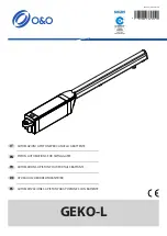
     Garage door opener

Motoriduttore per porte da garage

Motoréducteur pour portes de garage

Motorreductor para puertas de garaje

Garagentorantrieb

Motorredutor para portões de garagem

Motoreduktor do bram garażowych

HALO

Istruzioni ed avvertenze per l’installazione e l’uso

Instructions and warnings for installation and use

Instrucciones y advertencias para su instalación y uso

Anleitungen und Hinweise zu Installation und Einsatz

Instruções e advertências para a instalação e utilização

Instructions et avertissements pour l’installation et l’usage

IMAGES P. 45

IMMAGINI PAG. 45

IMAGES PAGE 45

IMÁGENES PÁG. 45

ABBILDUNGEN S. 45

IMAGENS PÁG.45

ILUSTRACJE STR. 45

Summary of Contents for HALO 900HA10

Page 1: ... ed avvertenze per l installazione e l uso Instructions and warnings for installation and use Instrucciones y advertencias para su instalación y uso Anleitungen und Hinweise zu Installation und Einsatz Instruções e advertências para a instalação e utilização Instructions et avertissements pour l installation et l usage IMAGES P 45 IMMAGINI PAG 45 IMAGES PAGE 45 IMÁGENES PÁG 45 ABBILDUNGEN S 45 IMA...

Page 2: ...ing holder shaft or on cross beam Traditional installation Manual opening of the door Fixing the LED rail opening limit stops Fixing the steel rail opening limit stops Electrical wiring Radio controls programming Learning of opening and closing values Changing a control unit parameter Control unit resetting Hole for access control mechanism Using the display programmer KUBE PRO KUBE wireless modul...

Page 3: ...cifications section Do not proceed with installation if any one of these devices is not suitable for its intended pur pose check that the devices purchased are sufficient to guarantee system safety and functionality perform a risk assessment including a list of the essential safety requirements as envisaged in An nex I of the Machinery Directive specifying the so lutions adopted The risk assessmen...

Page 4: ... the drive cannot be used with a driven part incorporating a wicket door unless the drive can only be operated with the wicket door in the safe position in the case of detection of an obstacle during its closing travel the garage door reverses its travel direction releasing the obstacle until it opens com pletely install the actuating member for the manual rele ase at a height less than 1 8m If re...

Page 5: ...r and 230Vac power supply 1000N 900HA10L For sectional doors up to 13 sqm with 3 m rail or 16 sqm with 4 m rail a 24 Vdc motor and a control unit with an integrated receiver and 120Vac power supply 1000N HEAD RAIL COMPATIBILITY HA7 HA10 HA10E HA10L 900RAB3 X X 900RAB3X1 X X 900RAB4 X X 900RAB6 X 900RAL30 X 900RAL40 X TECHNICAL SPECIFICATIONS 900HA7 900HA10 900HA10E 900HA10L Speed 12 cm s 12 cm s 1...

Page 6: ...0 Aluminium With integrated LED lighting Belt 4090 mm 1x4m 3660 mm 900RAB3X1 Steel Belt 3100 mm 3x1 03m 2670 mm 900RAB3 Steel Belt 3100 mm 1x3 1m 2670 mm 900RAB4 Steel Belt 4100 mm 1x4 1m 3670 mm 2 5 List of cables required In a typical plant the cables necessary for connection of the various devices are shown in the cable list table The cables used must be suitable for the type of installation fo...

Page 7: ...f a rubber mallet FIG 13 then insert the rail on the head taking care to match the adapter grooving to the motor pin s FIG 14 and connect the connector FIG 15 Check that the cables are inside their provided seats before positioning and tightening the upper plate FIG 16 to avoid crushing them Tighten the 4 cross head screws Open the side door remove the cable and connect the wires to the control un...

Page 8: ... In the event of a power failure and if the optional buffer battery is not available to unlock the automation system 4 7 Manual opening of the door PHASE DESCRIPTION 1 Pull the cord in order to bring the release lever to its vertical position FIG 30 2 Lift or lower the door manually 3 To reset the automation system move the cord so as to allow the release lever to fit fully back into the pulling s...

Page 9: ... GREEN LED indicating programming of radio parameters KUBE DYL DYL and KUBE connector SBS SBS STEP BY STEP key for automation system control DIP1 PH DIP2 EDGE Dip switch for disabling safety devices PH EDGE see FIG 48 SHIELD Antenna sheath ANT Antenna signal 4 11 Memorising a remote control If you have a KUBE PRO wireless module connect it to the control unit FIG 49 50 and follow the instructions ...

Page 10: ...cond from releasing the button the LED L2 on the receiver starts to flash 0 5s 0 5s 4 Confirm deleting by pressing the RADIO button 5 If deleting has been successful the LED L2 will emit one long flash 3s Note After 10 seconds of inactivity the receiver automatically exits the deleting phase PHASE DESCRIPTION EXAMPLE 1 Press and hold the RADIO button until the LED L2 lights up about 3 seconds and ...

Page 11: ...slider reaches its mechanical stop stops for a second and then restarts in the closing direction until the operation is complete 6 The values are stored 7 Perform AT LEAST one second full opening operation and one second full closing operation from the limit stop point without breaks to allow the control unit to store the motor stress along the travel 8 If the automation system fails to complete t...

Page 12: ...age Press or to select the desired language and then confirm with V If no language is selected press the X key the control unit will use the default language ENGLISH until the next power on In normal mode i e when the system is powered on normally and the display programmer is connected press X until the wording Key Automation is displayed In this way you will be able to view the following status ...

Page 13: ...l wiring diagram a drawing or photograph of the system the analysis of the risks and the solutions adopted to deal with them the manufacturer s declaration of con formity for all connected devices the operator s manual for every device and the system maintenance plan fix a dataplate with the details of the automation the name of the person who commissioned it the serial number and year of construc...

Page 14: ...tamolle o su architrave Installazione classica Apertura manuale della porta Fissaggio del finecorsa di apertura della guida led Fissaggio del finecorsa di apertura della guida in acciaio Collegamenti elettrici Programmazione dei radiocomandi Apprendimento delle quote di apertura e chiusura Modifica di un parametro della centrale Reset della centrale Foro per meccanismo antintrusione Utilizzo del p...

Page 15: ...e con particolare attenzione i dati riportati nel capitolo Caratteristiche tecniche Non effettuare l installazione se anche uno solo di questi dispositivi non è adatto all uso verificare se i dispositivi acquistati sono sufficienti a garantire la sicurezza dell impianto e la sua fun zionalità eseguire l analisi dei rischi che deve comprendere anche l elenco dei requisiti essenziali di sicurez za r...

Page 16: ...ere usato per porte aventi un raggio di apertura supe riore a 50 mm oppure aventi bordi o sporgenze su cui una persona potrebbe salire o ai quali aggrap parsi l apparecchio non può essere utilizzato con una porta guidata che incorpora una porta pedonale nel caso di rilevamento ostacolo durante la mano vra di chiusura il portone inverte la corsa liberan do l ostacolo fino ad aprirsi completamente i...

Page 17: ...ntegrato ed alimentazione a 230Vac 1000N 900HA10L Per porte sezionali fino a 13 mq con guida da 3 m o 16 mq con guida da 4 m motore 24 Vdc e centrale con ricevitore integrato ed alimentazione a 120Vac 1000N DATI TECNICI 900HA7 900HA10 900HA10E 900HA10L Velocità 12 cm s 12 cm s 12 cm s 12 cm s Forza 700 N 1000 N 1000 N 1000 N Cicli ora massimi 1 20 20 20 20 Cicli consecutivi ora max 1 10 10 10 10 P...

Page 18: ...a led integrati Cinghia 4090 mm 1x4m 3660 mm 900RAB3X1 Acciaio Cinghia 3100 mm 3x1 03m 2670 mm 900RAB3 Acciaio Cinghia 3100 mm 1x3 1m 2670 mm 900RAB4 Acciaio Cinghia 4100 mm 1x4 1m 3670 mm 2 5 Elenco cavi necessari Nell impianto tipico i cavi necessari per i collegamenti dei vari dispo sitivi sono indicati nella tabella elenco cavi I cavi utilizzati devono essere adatti al tipo di installazione ad...

Page 19: ...llo di gomma FIG 13 quindi inserire la guida sulla testa avendo cura di far combaciare i millerighe dell adattatore con quelli del perno motore FIG 14 e collegare il connettore FIG 15 Verificare che i cavi siano all interno delle sedi predisposte pri ma di posizionare e serrare la piastra superiore FIG 16 per evitare schiacciamenti degli stessi Serrare le 4 viti a croce Aprire lo sportello lateral...

Page 20: ...re l automazione muovere il cordino in modo da permettere alla leva di sblocco di rientrare completamente all interno del carrello di trascinamento FIG 36 4 Alzare o abbassare manualmente la porta fino ad agganciarla alla guida Seguire le indicazioni del paragrafo 4 1 da FIG 25 collegando però la staffa non sull asola ma sul foro singolo FIG 38 e seguendo le indicazioni di TAB 1B e TAB 2 Proseguir...

Page 21: ... l automazione disabilitando qualsiasi funzione compresa la chiusura automatica COM Comune ingressi SBS STOP L1 Led ROSSO di segnalazione per la programmazione dei parametri della centrale MENU Tasto per la programmazione dei parametri della centrale RADIO Tasto per la programmazione dei parametri della radio integrata L2 Led VERDE di segnalazione per la programmazione dei parametri della radio KU...

Page 22: ...po circa 1 secondo dal rilascio del tasto il LED L2 sulla ricevente inizia a lampeggiare 1s 1s 3 Per la cancellazione di tutta la memoria premere il tasto RADIO in corrispondenza del terzo lampeggio 4 Se la cancelllazione reset è andata a buon fine il LED L2 emetterà 1 lampeggio lungo FASE DESCRIZIONE ESEMPIO 1 Premere per almeno 5 secondi il tasto del nuovo radiocomando che si vuole memorizzare 5...

Page 23: ...ino a che il carrello raggiunge il fermo mecanico si ferma per un secondo e riprende in chiusura fino a completare la manovra 6 Le quote sono memorizzate 7 eseguire ALMENO una seconda manovra completa in apertura ed una seconda manovra completa in chiusura dal punto di fine corsa senza interruzioni per permettere alla centrale di memorizzare gli sforzi del motore lungo la corsa 8 Se l automazione ...

Page 24: ...derata e successivamente confermare con V Se non verrà selezionata nessuna lingua pressione tasto X la centrale utilizzerà la lingua di default INGLESE fino alla suc cessiva riaccensione In modalità normale cioè quando normalmente si da alimen tazione al sistema e il programmatore display è collegato pre mere X fino a quando compare la dicitura Key Automation In questo modo si potranno vedere i se...

Page 25: ...rmità le istruzioni e avvertenze d uso per l utilizzatore finale e il piano di manutenzione dell impianto accertarsi che l utilizzatore abbia compreso il corretto funzionamen to automatico manuale e di emergenza dell automazione informare anche in forma scritta l utilizzatore finale sui pericoli e ri schi ancora presenti Dopo la rilevazione di un ostacolo la porta si ferma in aper tura e viene esc...

Page 26: ...rps du moteur sur l arbre porte ressort ou architrave Installation classique Ouverture manuelle de la porte Fixation du fin de course d ouverture du rail Led Fixation du fin de course d ouverture du rail en acier Branchements électriques Programmation des radiocommandes Apprentissage des valeurs d ouverture et fermeture Modification d un paramètre de l unité centrale Réinitialisation de l unité ce...

Page 27: ...ion à réali ser À ce sujet contrôler tout particulièrement les données indiquées dans le chapitre Caractéristi ques techniques Ne pas effectuer l installation si ne serait ce qu un seul de ces dispositifs n est pas adapté à ce type d utilisation vérifier que les dispositifs achetés sont suffisants pour garantir la sécurité de l installation et son bon fonctionnement effectuer l analyse des risques...

Page 28: ...que opération de nettoyage et de maintenance de l automatisme le débrancher du réseau électrique les enfants doivent être surveillés afin de s assurer qu ils ne jouent pas avec l appareil ne pas utiliser la système d entraînement en cas d ouverture de porte dépassant 50 mm de diamètre ou de bords ou parties en saillie auxquel les une personne pourrait s agripper ou utiliser comme support l apparei...

Page 29: ...tation à 230 Vca 1000N 900HA10L Pour portes sectionnelles jusqu à 13 m2 rail de 3 m ou 16 m2 rail de 4 m moteur 24 Vcc et unité centrale à récepteur intégré et alimentation à 120 Vca 1000N INFORMATIONS TECHNIQUES 900HA7 900HA10 900HA10E 900HA10L Vitesse 12 cm s 12 cm s 12 cm s 12 cm s Puissance 700 N 1 000 N 1 000 N 1 000 N Cycles h maximum 1 20 20 20 20 Cycles consécutifs h max 1 10 10 10 10 Puis...

Page 30: ...nium Illumination à Leds intégrées Courroie 4 090 mm 1x4 m 3 660 mm 900RAB3X1 Acier Courroie 3100 mm 3x1 03m 2 670 mm 900RAB3 Acier Courroie 3100 mm 1x3 1m 2 670 mm 900RAB4 Acier Courroie 4100 mm 1x4 1m 3 670 mm 2 5 Liste des câbles nécessaires Dans l installation type les câbles nécessaires au raccordement des différents dispositifs sont indiqués dans le tableau correspondant Les câbles doivent ê...

Page 31: ...llant à faire correspondre les cannelures de l adaptateur avec celles du pivot du moteur FIG 14 et brancher le connecteur FIG 15 Vérifier que les câbles sont introduits dans les chemins pré vus avant d installer et de serrer la plaque supérieure FIG 16 pour éviter tout écrasement de ces derniers Serrer les 4 vis cruciformes Ouvrir le panneau latéral extraire le câble et raccorder les fils à l unit...

Page 32: ...ellement 3 Pour réinitialiser l automatisme utiliser le cordon pour permettre au levier de débrayage de se rétracter complètement à l intérieur du chariot FIG 36 4 Soulever ou abaisser manuellement la porte jusqu à la bloquer sur le rail Suivre les instructions du par 4 1 à partir de la FIG 25 en raccor dant la bride sur l orifice et non sur la fente FIG 38 et en suivant les indications du TAB 1B ...

Page 33: ...OP 2 fois pour la fonction OUVERTURE PARTIELLE 3 fois pour la fonction OUVERTURE SEULE 4 fois pour la fonction LUMIÈRE ON OFF 5 fois pour la fonction PRÉCONFIGURÉE touche 1 SBS touche 2 OUVERTURE PARTIELLE touche 3 OUVERTURE SEULE touche 4 LUMIÈRE ON OFF 6 fois pour la fonction TOUCHE MURALE touche 1 FERMETURE STOP touche 2 OUVERTURE STOP touche 3 VENTILATION touche 4 LUMIÈRE ON OFF 2 La Led L2 cl...

Page 34: ... après le relâchement de la touche la Led 2 du récepteur commence à clignoter 0 5s 0 5s 4 Confirmer l effacement en appuyant sur la touche RADIO 5 Si l effacement a été correctement effectué la Led L2 émet un clignotement prolongé 3s Rem Après 10 secondes d inactivité le récepteur sort automatiquement de la phase d effacement PHASE DESCRIPTION EXEMPLE 1 Maintenir la touche RADIO enfoncée jusqu à l...

Page 35: ... au contact du chariot avec la butée mécanique s arrête durant une seconde et redémarre en ouverture jusqu à la fin de la manœuvre 6 Les valeurs sont mémorisées 7 effectuer AU MINIMUM une seconde manœuvre complète en ouverture et une autre en fermeture à partir du fin de course et sans interruption ceci afin de permettre à l unité centrale de mémoriser les efforts du moteur le long de la course 8 ...

Page 36: ...langue n est sélectionnée pression touche X l unité centrale utilisera la langue par défaut ANGLAIS jusqu à la pro chaine mise en fonction En mode normal c est à dire en cas d alimentation normale du système et de branchement de l écran du programmateur ap puyer sur X jusqu à l affichage de Key Automation Les mes sages d état suivants s affichent OPTIONS DISPLAY SÉLECTION LANGUE KEY AUTOMATION ÉVÉ...

Page 37: ...contenir le schéma électrique le dessin ou la photo de l installation l analyse des risques et les solutions adoptées la déclaration de conformité du fabricant de tous les dispositifs raccordés le guide technique de chaque dispositif et le plan de maintenance de l installation fixer sur le portail ou la porte une plaquette mentionnant les données de l automatisme le nom du responsable de la mise e...

Page 38: ...muelles o en dintel Instalación clásica Apertura manual de la puerta Fijación del final de carrera de apertura de la guía LED Fijación del final de carrera de apertura de la guía de acero Conexiones eléctricas Programación de los radiomandos Aprendizaje de las medidas de apertura y cierre Modificación de un parámetro de la central Restablecimiento de la central Agujero para el mecanismo antiintrus...

Page 39: ...ente los datos indicados en el capítulo Características técnicas No realice la instalación incluso si uno de dichos dispositivos no es adecuado para el uso compruebe que los dispositivos comprados sean suficientes para garantizar la seguridad del siste ma y su funcionamiento realice el análisis de los riesgos que debe incluir la lista de los requerimientos esenciales de segu ridad indicados en el ...

Page 40: ...los elementos fijos de alre dedor controle que los niños no jueguen con el disposi tivo el motor no debe usarse con puertas que tengan aberturas que superen los 50 mm de diámetro o que tengan bordes o partes salientes en las que una persona pueda asirse o pararse el dispositivo no puede ser utilizado con una puer ta automatizada que incorpora una puerta peato nal en caso de detección de obstáculos...

Page 41: ...n motor de 24 Vcc y central con receptor integrado y alimentación de 230 Vca 1000N 900HA10L Para puertas seccionales de hasta 13 m con guía de 3 m o 16 m con guía de 4 m motor de 24 Vcc y central con receptor integrado y alimentación de 120 Vca 1000N DATOS TÉCNICOS 900HA7 900HA10 900HA10E 900HA10L Velocidad 12 cm s 12 cm s 12 cm s 12 cm s Fuerza 700 N 1000 N 1000 N 1000 N Ciclos hora máximos 1 20 ...

Page 42: ...n con LED integrados Correa 4090 mm 1x4 m 3660 mm 900RAB3X1 Acero Correa 3100 mm 3x1 03m 2670 mm 900RAB3 Acero Correa 3100 mm 1x3 1m 2670 mm 900RAB4 Acero Correa 4100 mm 1x4 1m 3670 mm 2 5 Lista de los cables necesarios En el sistema típico los cables necesarios para las conexiones de los distintos dispositivos están indicados en la tabla lista de los ca bles Los cables utilizados deben ser adecua...

Page 43: ... procurando hacer coincidir el elemento estriado del adaptador con aquellos del eje del motor FIG 14 y conecte el conector FIG 15 Compruebe que los cables estén dentro de sus alojamientos antes de colocar y apretar la placa superior FIG 16 para evitar aplastarlos Apriete los 4 tornillos en cruz Abra la tapa lateral retire el cable y conecte los cables a la central FIG 17 Cierre la tapa Apoye el mo...

Page 44: ...ta manualmente 3 Para restablecer la automatización mueva el tirador de manera que la palanca de desbloqueo vuelva a entrar completamente en el carro de arrastre FIG 36 4 Levante o baje la puerta manualmente hasta que se enganche en la guía Siga las instrucciones del apartado 4 1 de la FIG 25 pero conec tando el soporte en el agujero solo y no en el agujero alargado FIG 38 y siguiendo las indicaci...

Page 45: ...45 FIGURES x2 x4 x4 x4 x4 x4 x2 x6 x4 x4 x2 x1 x4 x1 x1 x1 x1 x1 x1 x1 x2 x1 x1 x1 x1 x1 5 1 2 4 3 RAL30 RAL40 RA3X1 RA3X1 RAB3 RAB4 RA3 5 4 13 10 13 Ø 7 7 6 9 8 26 28 mm Ø 13 mm 1 1 2 11 10 12 PUSH ...

Page 46: ...46 15 16 19 22 17 18 21 20 COM brown LED green NEG black CLICK A A 5 cm 24 25 1 2 3 23 14 13 ...

Page 47: ...47 27 28 26 30 29 36 34 35 31 32 33 DOOR GARAGE 37 ...

Page 48: ...48 A A 3 cm 44 43 42 H 10cm 45 46 Ø 7 mm 1 2 49 47 50 41 39 1 2 40 38 ...

Page 49: ...E EDGE SBS STOP COM BATTERY PACK STOP EDGE INDICATOR FLASH NEGATIVE F1AT COM LED IND FLASH SEN 2 3 4 1 1 2 TX RX NC PHOTOCELL ECLIPSE FLASHING LIGHT GND _ 12 24 AC DC GND _ 12 24 AC DC COM OUT 3 4 1 2 5 6 SHIELD SAFETY NOTJUMPED PH EDGE SAFETY JUMPED FOR EDGE CONFIGURATION SEE TABLE 3 ANT KUBE DYL L1 L2 SBS 1 2 Ø 10 mm 1 2 ...

Page 50: ...te à referida nos quadros consoante as diversas geometrias e curvaturas dos perfis de guia dos portões seccionados PL Użytkowa wysoko przejścia mo e zmienia sięwzględem wskazańw tabelach w zależności od geometrii i krzywizn profili prowadzących bram segmentowych TAB 1B TAB 1A B mm L mm Arm Type Clear passage H 10 cm m Door Height H m Note 130 380 L2 2 5 2 6 door springs in the back 150 380 L2 2 5 ...

Page 51: ...tomatische Schließzeit nach Transit auf Fotozellen Sek Tempo de fecho automático após passagem pelas fotocélulas s Czas zamykania automatycznego po przejściu nad fotokomórkami sek 1 off 2 5 sec 3 10 sec 4 15 sec 5 20 sec 6 25 sec 7 30 sec 1 off 3 Obstacle sensitivity Sensibilità su ostacolo Sensibilité à l obstacle Sensibilidad sobre el obstáculo Empfindlichkeit auf Hindernis Sensibilidade em obst...

Page 52: ...4 30 cm 5 40 cm 6 50 cm 7 60 cm 8 70 cm 9 80 cm 10 90 cm 1 off 8 Closing limit stop advance cm Anticipo finecorsa di chiusura cm Anticipation fin de course de fermeture cm Anticipación final de carrera de cierre cm Voreilung Schließendschalter cm Antecipação fim de curso de fecho cm Wyprzedzenie wyłącznika krańcowego zamykania cm 1 off 2 0 5 cm 3 1 cm 4 1 5 cm 5 2 cm 6 2 5 cm 7 3 cm 8 3 5 cm 9 4 c...

Page 53: ...la función APERTURA PARCIAL 3 veces para la función SOLO ABRIR 4 veces para la función LUZ ON OFF 5 veces para la función PRECONFIGURADA pulsador 1 SBS pulsador 2 APERTURA PARCIAL pulsador 3 SOLO ABRIR pulsador 4 LUZ ON OFF 6 veces para la función PULSADOR EN PARED pulsador 1 CERRAR STOP pulsador 2 ABRIR STOP pulsador 3 VENTILACIÓN pulsador 4 LUZ ON OFF 2 El LED L2 realiza un número de destellos q...

Page 54: ...r 0 5s 0 5s 4 Confirme la cancelación presionando el pulsador RADIO 5 Si la cancelación ha sido correcta el LED L2 emitirá un destello prolongado 3s Nota Transcurridos 10 segundos de inactividad el receptor sale automáticamente de la fase de cancelación ETAPA DESCRIPCIÓN EJEMPLO 1 Presione y mantenga presionado el pulsador RADIO hasta que se encienda el LED L2 3 segundos aprox y luego se apague 3 ...

Page 55: ...ta cuando el carro llega al tope mecánico se detiene por un segundo y reanuda el cierre hasta que se completa la maniobra 6 Las medidas se memorizan 7 realice AL MENOS una segunda maniobra completa de apertura y una segunda maniobra completa de cierre desde el punto de final de carrera sin interrupciones para permitir que la central memorice los esfuerzos del motor a lo largo del recorrido 8 Si la...

Page 56: ...a deseado y luego confirme con V Si no se seleccionara ningún idioma pulsador X la central uti lizará el idioma por defecto INGLÉS hasta el próximo encen dido En el modo normal es decir cuando normalmente se activa la alimentación del sistema y el programador con pantalla está conectado pulse X hasta que se visualice Key Automation De esta manera se podrán ver los siguientes mensajes de estado OPC...

Page 57: ... el diagrama eléctrico el dibujo o la foto del sistema el análisis de los riesgos y las soluciones tomadas la declaración de conformidad del fabricante de todos los dispositivos conectados el manual de instrucciones de cada dispositivo y el plan de mantenimiento del sistema coloque en la puerta una placa con los datos del automatismo el nombre de la persona responsable de la puesta en servicio el ...

Page 58: ...stallation mit Motorkörper auf Federhaltewelle oder Sturz Traditionelle Installation Manuelles Öffnen des Tors Befestigung des Öffnungsendschalters der LED Führung Befestigung des Öffnungsendschalters der Stahlführung Elektrische Anschlüsse Programmierung der Funksteuerungen Erlernen der Öffnungs und Schließmaße Ändern eines Parameters der Steuereinheit Reset der Steuereinheit Loch für den Intrusi...

Page 59: ...ass die für die Automatisierung vorgesehenen Vorrichtungen für die zu realisieren de Anlage geeignet sind Diesbezüglich aufmer ksam die im Kapitel Technische Eigenschaften aufgeführten Daten prüfen Die Installation nicht durchführen wenn auch nur eine der Vorrichtun gen nicht für den Gebrauch geeignet ist Sicherstellen dass die erworbenen Vorrichtungen ausreichend sind um die Sicherheit und Funkti...

Page 60: ...en um sicherzu stellen dass sie nicht mit dem Gerät spielen Der Antrieb wird nicht verwendet für Türen mit Öff nungen von mehr als 50 mm Durchmesser oder Kanten oder vorstehenden Bauteilen die eine Person greifen kann oder auf denen eine Person stehen kann Das Gerät darf mit einer automatisierten Tür mit eingebauter Fußgängertür nicht verwendet wer den Bei Hinderniserfassung während des Schließung...

Page 61: ...t 24Vdc Motor und Steuereinheit mit integriertem Empfänger und 230Vac Speisung 1000N 900HA10L Für Sektionaltore bis 13 m2 mit 3 m langer Führung oder 16 m2 mit 4 m langer Führung 24Vdc Motor und Steuereinheit mit integriertem Empfänger und 120Vac Speisung 1000N TECHNISCHE DATEN 900HA7 900HA10 900HA10E 900HA10L Geschwindigkeit 12 cm s 12 cm s 12 cm s 12 cm s Kraft 700 N 1000 N 1000 N 1000 N Max Zyk...

Page 62: ...ium Mit Beleuchtung mit integrierten LEDs Riemen 4090 mm 1x4m 3660 mm 900RAB3X1 Stahl Riemen 3100 mm 3x1 03m 2670 mm 900RAB3 Stahl Riemen 3100 mm 1x3 1m 2670 mm 900RAB4 Stahl Riemen 4100 mm 1x4 1m 3670 mm 2 5 Liste der erforderlichen Kabel Die für eine typische Anlage notwendigen Anschlusskabel der ver schiedenen Vorrichtungen sind in der Tabelle der Kabelliste ange geben Die verwendeten Kabel müs...

Page 63: ...ters mit denen des Motorzapfens zusammentreffen ABB 14 und den Verbinder anschließen ABB 15 Prüfen dass sich die Kabel in ihren Aufnahmen befinden be vor die obere Platte positioniert und befestigt wird ABB 16 damit sie nicht gequetscht werden Die 4 Schrauben gekreuzt festziehen Die seitliche Klappe öffnen das Kabel herausziehen und die Dräh te an der Steuereinheit anschließen ABB 17 Die Klappe wi...

Page 64: ... heben oder senken 3 Um die Automatisierung wieder betriebsfähig zu machen die Kordel so bewegen dass der Entriegelungshebel wieder komplett in den Mitnahmeschlitten eindringen kann ABB 36 4 Das Tor manuell heben oder senken bis es an der Führung angekuppelt wird Die Anweisungen im Absatz 4 1 ab ABB 25 befolgen dabei jedoch den Bügel nicht auf dem Langloch sondern auf dem Einzelloch an schließen A...

Page 65: ... für die Funktion LICHT EIN AUS 5 Mal für die Funktion VOREINGESTELLT Taste 1 SBS Taste 2 TEILÖFFNUNG Taste 3 NUR ÖFF NEN Taste 4 LICHT EIN AUS 6 Mal für die Funktion MAUERTASTE Taste 1 SCHLIESSEN STOPP Taste 2 ÖFFNEN STOPP Taste 3 LÜFTUNG Taste 4 LICHT EIN AUS 2 Die LED L2 blinkt so oft wie für den gewählten Ausgang notwendig zwischendurch jeweils mit einer Pause von 1 Sekunde 1s 1s 3 Innerhalb v...

Page 66: ...reigesetzt wurde beginnt die LED L2 auf dem Empfänger zu blinken 0 5s 0 5s 4 Auf die Taste RADIO drücken um die Löschung zu bestätigen 5 Wenn das Löschen erfolgreich stattgefunden hat blinkt die LED L2 einmal lang 3s Anm Nach 10 Sekunden langer Untätigkeit verläßt der Empfänger automatisch die Programmierungsphase PHASE BESCHREIBUNG BEISPIEL 1 Die Taste RADIO drücken und gedrückt halten bis die LE...

Page 67: ...der Parameter der Steuereinheit 4 Das Tor muss eine Öffnung mit niedriger Geschwindigkeit ausführen Wenn das Tor schließt nochmals auf die Taste drücken um es zu stoppen und erneut um die Richtung umzukehren Die Prozedur ist nur dann erfolgreich wenn das erste Manöver eine Öffnung ist und so endet dass der Schlitten gegen den zuvor positionierten mechanischen Anschlag prallt 5 Das Tor bewegt sich ...

Page 68: ...e gewünschte Sprache zu wählen dann mit V bestätigen Wenn keine Sprachwahl erfolgt Drücken der Taste X benutzt die Steuereinheit bis zur nächsten Wiedereinschaltung die De faultsprache ENGLISCH Im Normalmodus d h wenn das System normal gespeist wird und das Programmierungsdisplay angeschlossen ist auf X drücken bis der Schriftzug Key Automation erscheint In die ser Weise sind folgende Zustandsmeld...

Page 69: ... Jahre lang aufbewahrt werden sie umfassen den Schaltplan die Zeichnung oder ein Foto der Anlage die Risikoanalyse und die jeweiligen Lösungen die Konformitätserklärung des Herstellers bezüglich aller angeschlossenen Vorrichtungen und den Wartungsplan der Anlage Am Tor oder an der Tür ein Schild mit den Daten der Automatisierung dem Namen des Verantwortlichen der Inbetriebnahme der Seriennummer de...

Page 70: ... veio porta molas ou na viga Instalação normal Abertura manual do portão Fixação do fim de curso de abertura da guia com leds Fixação do fim de curso de abertura da guia de aço Ligações elétricas Programação dos comandos Memorização das quotas de abertura e fecho Modificação de um parâmetro da central Reset à central Furo para mecanismo contra intrusão Utilização do programador com ecrã Ligação do...

Page 71: ...sticas técnicas Não fazer a instalação mesmo se apenas um destes dispositi vos não for apropriado para a utilização Verificar se os dispositivos adquiridos são sufi cientes para garantir a segurança do sistema e o seu funcionamento Analisar os riscos verificando também a lista dos requisitos essenciais de segurança constantes do Anexo I da Diretiva Máquinas e indicar as so luções adotadas A anális...

Page 72: ...as que tenham aberturas com diâmetro superior a 50 mm ou que tenham arestas ou partes salientes às quais alguém possa agarrar se ou onde possa pendurar se o aparelho não pode ser utilizado com uma porta automatizada que possui uma porta para peões em caso de deteção de um obstáculo durante o fe cho o portão inverte o curso e liberta o obstáculo até se abrir totalmente instalar o controlo para libe...

Page 73: ... com recetor incorporado e alimentação 230 Vac 1000N 900HA10L Para portões seccionados de até 13 m2 com guia de 3 m ou de 16 m2 com guia de 4 m motor 24 Vdc e central com recetor incorporado e alimentação 120 Vac 1000N DADOS TÉCNICOS 900HA7 900HA10 900HA10E 900HA10L Velocidade 12 cm s 12 cm s 12 cm s 12 cm s Força 700 N 1000 N 1000 N 1000 N Ciclos hora máx 1 20 20 20 20 Ciclos consecutivos hora má...

Page 74: ...90 mm 1x3 m 2660 mm 900RAL40 Alumínio Iluminação com leds incorporados Correia 4090 mm 1x4 m 3660 mm 900RAB3X1 Aço Correia 3100 mm 3x1 03m 2670 mm 900RAB3 Aço Correia 3100 mm 1x3 1m 2670 mm 900RAB4 Aço Correia 4100 mm 1x4 1m 3670 mm 2 5 Lista de cabos necessários Para o sistema padrão os cabos necessários para ligar os vários dispositivos estão indicados no quadro com a lista de cabos Os cabos uti...

Page 75: ...ltar a posicionar o motor na placa Em seguida atarraxar parcialmente os parafusos laterais com pridos FIG 38 Não atarraxar com força para não partir a sede das porcas Apertar as contra porcas FIG 27 e atarraxá las por completo mantendo parados os parafusos com uma chave de boca Não rodar os parafusos para evitar partir as sedes das porcas rodar apenas as contra porcas para as atarraxar Atarraxar o...

Page 76: ...o o automatismo movimentar o cordão de modo a permitir que a alavanca de desbloqueio volte completamente para dentro do carro de arrastamento FIG 36 4 Levantar ou baixar manualmente o portão até que se enganche na guia Seguir as instruções do parágrafo 4 1 da FIG 25 mas não ligar a placa à abertura mas ao orifício único FIG 38 e de acordo com as instruções do quadro 1B e quadro 2 Continuar de acor...

Page 77: ... ABERTURA PARCIAL 3 vezes para a função APENAS ABERTURA 4 vezes para a função LUZ ON OFF 5 vezes para a função PRÉ CONFIGURADA tecla 1 SBS tecla 2 ABERTURA PARCIAL tecla 3 APENAS ABERTURA tecla 4 LUZ ON OFF 6 vezes para a função TECLA MURAL tecla 1 FECHA STOP tecla 2 ABRE STOP tecla 3 VENTILAÇÃO tecla 4 LUZ ON OFF 2 O Led L2 emite um número de sinais intermitentes correspondente à saída selecionad...

Page 78: ...cla RADIO 5 Se a eliminação for concluídA o LED L2 emitirá 1 sinal intermitente longo 3s Obs Depois de 10 segundos de inatividade o recetor sai automaticamente da fase de eliminação FASE DESCRIÇÃO EXEMPLO 1 Premir e manter premida a tecla RADIO até que se acenda o LED L2 cerca de 3 segundos e depois se apague cerca de 3 segundos Libertar a tecla 3s 3s 2 Cerca de 1 segundo após libertar a tecla o L...

Page 79: ...o anteriormente 5 O portão chega à posição de abertura completa quando o carro alcança o batente mecânico para durante um segundo e volta a fechar se até completar a manobra 6 As quotas são memorizadas 7 Fazer PELO MENOS uma segunda manobra completa de abertura e uma segunda manobra completa de fecho a partir do ponto de fim de curso sem interrupções para permitir que a central memorize os esforço...

Page 80: ...ioma Premir o para selecionar o idioma desejado e em seguida confirmar com a tecla V Se não for selecionado nenhum idioma com a tecla X a cen tral utilizará o idioma por default INGLÊS até que seja ligado de novo No modo normal ou seja com o sistema alimentado normal mente e com o programador com ecrã ligado premir X até apa recer a escrita Key Automation Deste modo serão apresen tadas as seguinte...

Page 81: ...ema elétrico o desenho ou foto do sistema a análise dos riscos e as soluções adotadas a declaração de conformidade do fabricante de todos os dispositivos ligados o manual de instruções de cada dispositivo e o plano de manutenção do sistema Fixar no portão ou na porta uma placa com os dados da automação o nome do responsável da colocação em serviço o número de série e o ano de fabrico a marca CE Fi...

Page 82: ...ontaż klasyczny Ręczne otwieranie bramy garażowej Mocowanie wyłącznika krańcowego otwierania na prowadnicy LED Mocowanie wyłącznika krańcowego otwierania na prowadnicy stalowej Podłączenia elektryczne Programowanie pilotów Programowanie współrzędnych otwierania i zamykania Modyfikacja jednego z parametrów centrali Reset parametrów centrali Otwór do mechanizmu antywyważeniowego Obsługa programatora...

Page 83: ...zenia auto matyki są przydatne do danych celów i dosto sowane do wykonywanej instalacji W tym celu sprawdzić dokładnie dane podane w rozdziale Parametry techniczne Nie przystępować do wykonywania instalacji w przypadku gdy nawet jeden element nie nadaje się do użycia Sprawdzić czy urządzenia obecne w zestawie są wystarczające do zapewnienia bezpieczeństwa in stalacji oraz jej poprawnego działania ...

Page 84: ...czy możliwość niewłaściwej obsługi urządzenia nie stosować napędu w bramach z otworami o średnicy większej niż 50 mm i bramach mających krawędzie lub wystające części które można chwycić dłonią lub stanąć na nich urządzenie nie może być wykorzystywane do ob sługi bramy automatycznej w którą wbudowane jest przejście dla pieszych w przypadku wykrycia przedmiotu w trakcie zamykania brama zmienia swój...

Page 85: ... m2 z prowadnicą 3 m lub 16 m2 z prowadnicą 4 m silnik 24 Vdc centrala z wbudowanym odbiornikiem i zasilaniem 120 Vac 1000N PARAMETRY TECHNICZNE 900HA7 900HA10 900HA10E 900HA10L Prędkość 12 cm s 12 cm s 12 cm s 12 cm s Siła 700 N 1000 N 1000 N 1000 N Cykle godz maksymalnie 1 20 20 20 20 Cykle kolejne maks 1 10 10 10 10 Moc nominalna 80W 100 W 100 W 100 W Moc w trybie czuwania 5 5 W 5 5 W 0 5 W 5 5...

Page 86: ...900RAB3X1 Stal Pas 3100 mm 3x1 03m 2670 mm 900RAB3 Stal Pas 3100 mm 1x3 1m 2670 mm 900RAB4 Stal Pas 4100 mm 1x4 1m 3670 mm 2 5 Wykaz niezbędnych przewodów elektrycznych W przypadku typowej instalacji rodzaje przewodów elektrycznych niezbędnych do podłączenia różnych urządzeń podane zostały w tabeli zawierającej wykaz przewodów Wykorzystywane przewody elektryczne powinny być dostosowane do rodzaju ...

Page 87: ...metalowy adapter do otworu na prowadnicy posługując się gumowym młotkiem RYS 13 Nasunąć prowadnicę na głowicę zwracając uwagę aby część żłobkowana adaptera pokryła się z częścią żłobkowaną sworznia silnika RYS 14 Podłączyć złącze RYS 15 Przed umieszczeniem i dokręceniem płyty górnej sprawdzić czy przewody elektryczne znajdują się wewnątrz przygotowa nych gniazd RYS 16 aby zapobiec ich zgnieceniu D...

Page 88: ... linkę w taki sposób aby umożliwić całkowite wsunięcie dźwigni odblokowa nia do wnętrza wózka ciągnącego FIG 36 4 Podnieść lub obniżyć bramę garażową ręcznie aż do zaczepienia na prowadnicy Stosować się do wskazówek w punkcie 4 1 od RYS 25 mocując jednakże uchwyt nie na otworze podłużnym ale pojedynczym RYS 38 Stosować się do wskazań w TAB 1B i TAB 2 Kontynuować stosując się do wskazówek w punkcie...

Page 89: ... USTAWIONE W TRYBIE przycisk 1 SBS przycisk 2 CZĘŚCIOWE OTWARCIE przycisk 3 TYLKO OTWIERANIE przycisk 4 OŚWIETLENIE ON OFF 6 razy dla funkcji PRZYCISK NA ŚCIANIE przycisk 1 ZAMYKANIE STOP przycisk 2 OTWIERANIE STOP przycisk 3 WENTYLACJA przycisk 4 OŚWIETLENIE ON OFF 2 Dioda LED L2 mignie liczbę razy odpowiadającą wybranemu wyjściu przerywanych pauzą trwającą 1 sekundę 1s 1s 3 W ciągu 10 sekund nal...

Page 90: ...ać 0 5s 0 5s 4 Potwierdzić skasowanie wciskając przycisk RADIO 5 Jeżeli kasowanie zakończyło się powodzeniem dioda LED L2 wykona jedno długie mignięcie 3s Uw Po 10 sekundach braku aktywności odbiornik kończy automatycznie fazę kasowania FAZA OPIS PRZYKŁAD 1 Wcisnąć i przytrzymać przycisk RADIO do momentu zaświecenia się diody LED L2 ok 3 sekundy a potem jej zgaśnięcia ok 3 sekundy Zwolnić przycisk...

Page 91: ... momentu osiągnięcia przez wózek hamulca mechanicznego zatrzymuje się na jedną sekundę i wznawia ruch w kierunku zamykania aż do jego ukończenia 6 Współrzędne zostają wprowadzone do pamięci 7 Wykonać CO NAJMNIEJ jeden kolejny kompletny manewr otwierania i jeden kolejny manewr zamykania od punktu wyłącznika krańcowego bez przerywania aby umożliwić centrali wprowadzenie do pamięci sił działania siln...

Page 92: ...y po doprowadzeniu zasilania do układu i przy podłączonym programatorze z wyświetlaczem wciskać X do momentu aż pojawi się napis Key Automation W ten sposób można będzie zobaczyć następujące komunikaty stanu OPCJE WYŚWIETLACZ WYBÓR JĘZYKA KEY AUTOMATION ZDARZENIE OPIS WSKAZANIA LAMPY OSTRZEGAWCZEJ ORAZ DIODY STEROWANIA CENTRALI otwieranie Brama garażowa w trakcie otwierania otwieranie na użytek pr...

Page 93: ...owinna ona zawierać schemat elektryczny rysunek lub zdjęcie instalacji analizę zagrożeń wraz z zastosowanymi rozwiązaniami deklaracje zgodności wydane przez producentów wszystkich podłączonych urządzeń instrukcje obsługi każdego z urządzeń oraz harmonogram konserwacji instalacji Umieścić na bramie tabliczkę zawierającą dane dotyczące automatyki nazwisko osoby odpowiedzialnej za uruchomienie numer ...

Page 94: ...94 PL UWAGI ...

Page 95: ...rective 2011 65 EU Secondo quanto previsto dalle seguenti norme armonizzate In accordance with the following harmonized standards regulations EN 55014 1 2017 EN 55014 2 2015 EN 61000 3 2 2014 EN 61000 3 3 2013 A1 2018 EN 301489 1 V2 2 0 EN 301489 3 V2 1 1 EN 301489 17 V3 2 0 EN 61000 6 3 2007 A1 2011 EN 61000 6 2 2017 EN 60335 1 2012 A11 2014 A1 2015 A2 IEC 2016 A12 2017 A13 2017 EN 60335 2 95 201...

Page 96: ...Key Automation S r l Via Meucci 23 30027 San Donà di Piave VE T 39 0421 307 456 F 39 0421 656 98 info keyautomation it www keyautomation it Instruction version Designed and engineered in Italy manufactured in Extra EU ...

Reviews: