background image

SPECIFICATIONS

Type .......................................... Subwoofer system with built-in

amplifier

[Amplifier]

100 watts RMS, at 4 W, from 20 Hz to 200 Hz with no more
than 0.09 % total harmonic distortion.

Phase Switching ..................... NORMAL, REVERSE
Input Sensitivity & Input Impedance
  RCA-type pin-plug jack ....... 45 mV (12 kW)
  Push-type terminals ............ 0.7 V (5 kW)
Supply Voltage ....................... U.S.A. and Canada

AC 120 V

Other  countries AC 110 V - 120 V/ AC 220 V - 240 V

Rated Power Consumption .. 110 W

[Speaker]
Enclosure 
................................. Bass-Reflex, Floor Standing

Type

Speaker Units ......................... 250 mm Cone type
Nominal Impedance .............. 4 W
Dimensions .............................. Width : 300 mm (11-13/16")

Height : 420 mm (16-9/16")
Depth : 444 mm (17-1/2")

Net Weight .............................. 16 kg (35.3 lb)
Supplied Accessories ............ Pin-plug cord

×

 1

.................................................... Pads

(

×

 4)

NOTE: DO NOT REMOVE THE GRILLE.

Note:
KENWOOD follows a policy of continuous advancements in development. For this reason specifications may be changed without notice.
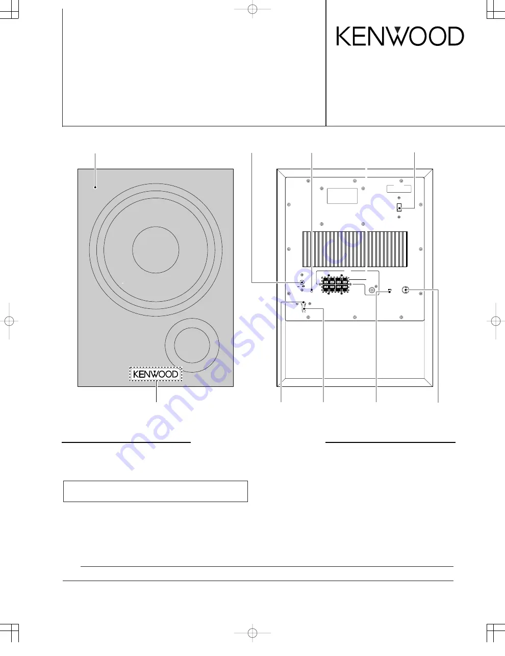
LINE

PHASE

LEVEL CONTROL

REVERSE

NORMAL

FROM AMPLIFIER

+

+

+

+

TO SPEAKERS

POWER

ON

R

L

R

L

INPUT

OFF

SERIAL NO.

Level control knob
(K29-0576-08)

POWER SUBWOOFER

SW-3HT

SERVICE MANUAL

© 1997-11/B51-5394-00 (K/K) 1396

* Refer to parts list on page 7.

LED
(B30-1822-08)

AC cord *
(E30-)

Cloth frame assy
(B06-1144-08)

Badge
(B43-0847-04)

Slide switch voltage *
(S31-)

Slide switch phase
(S62-0207-08)

Power knob (REAR)
(K29-0579-08)

Speaker terminal
(E21-0279-08)

Cord bushing
(J42-0234-08)

SW-3HT 

COVER 

2P 


98.4.25 

8:27 

PM 

  y [ W  2

Summary of Contents for SW-3HT

Page 1: ...ht 420 mm 16 9 16 Depth 444 mm 17 1 2 Net Weight 16 kg 35 3 lb Supplied Accessories Pin plug cord 1 Pads 4 NOTE DO NOT REMOVE THE GRILLE Note KENWOOD follows a policy of continuous advancements in development For this reason specifications may be changed without notice LINE PHASE LEVEL CONTROL REVERSE NORMAL FROM AMPLIFIER TO SPEAKERS POWER ON R L R L INPUT OFF SERIAL NO Level control knob K29 057...

Page 2: ...NTENTS ADJUSTMENT No ITEM INPUT SETTINGS OUTPUT SETTINGS AMPLIFIER SETTINGS ALIGNMENT POINTS ALIGN FOR FIG Unless otherwise specified the individual switches should be set as following POWER ON NO SIGNAL INPUT 1 IDLE CURRENT Connect a DC voltmeter to R611 VOLUME 0 VR601 5 mV a Dc voltmeter 5 mV R611 a SW 3HT COVER 2P 98 4 25 8 27 PM y W 3 ...

Page 3: ...A C E B D 2 1 3 5 7 4 6 PC BOARD Component side view Refer to the schematic diagram for the value of resistors and capacitors 3 SW 3HT COVER 2P 98 4 25 8 27 PM y W 6 ...

Page 4: ...4 1 2K R102 4 7K 1 2 3 4 5 6 7 8 C871 C872 100u25 1K R873 R874 1K 220P C873 470 JK102 IC202 1 2 IC202 2 2 D401 Q403 1 2 IC101 2 2 IC101 1 2 IC201 IC201 2 2 ZD101 ZD102 W803 STAND BY MTZ16B ZD871 872 MTZJ5 1B ZD815 MTZJ30B ZD101 102 D3SBA20 D801 1SR139 100 D651 653 811 814 851 B30 1822 08 D401 D814 CN601 NJM4558L IC101 201 202 uPC1298V IC601 uPC1237HA IC651 NJM2072D IC851 Q403 651 851 2SC1815GR 2SA...

Page 5: ...ATCH SW AUTO RECOVERY FLIP FLOP 1 Q602 603 R662 10K 2 2u50 C652 1K R661 R663 820 R614 10K 4 7K 0 047 C610 10 1W R612 R613 R660 R664 470K C609 100P 100P C608 R611 0 22 C611 1u50 2 7 R609 1 4W 1 4W R607 10 C607 10 1 4W R608 100u63 11 1K R606 100P C605 R605 2 7K 22K C651 4 7u50 R651 R658 12K 56K R655 R659 22u16 C656 C655 47u10 68K R657 R654 22K C659 22u16 R653 22K R652 33K C660 2 7K 1u50 R656 47K 100...

Page 6: ...x8 3x8 N09 3668 05 N44 4014 45 N35 4008 45 N82 3012 45 N89 3010 45 N89 3008 45 N89 3006 46 N34 3010 45 N82 2608 46 N89 3008 46 SW 3HT 620 622 660 780 779 790 771 771 759 772 774 777 771 630x2 771 771 771 778 759 775 773 630x2 T1 641 611 SPK1 613 625 642 632 621 633 Bx12 Dx2 H H H H Cx4 Fx6 Dx3 Dx2 Ex2 G G Kx2 Kx2 Bx8 Jx2 1 2 3 A B Parts with exploded view numbers larger than 700 are not supplied S...

Page 7: ...C875 876 CE04KW1E470M ELECTRO 47UF 25WV C901 C91 1441 08 CERAMIC 4700PF 250WV C902 903 C91 0211 08 POLYEST 0 047UF 250WV JK101 E21 0279 08 SPEAKER TERMINAL F901 F05 1623 05 FUSE 1 6A 250V Y F901 F50 0072 05 FUSE 3 15A 125V KP F902 903 F05 8013 05 FUSE 800MA 250V Y F902 903 F50 0062 05 FUSE 800MA 250V KP F904 F05 1623 05 FUSE 1 6A 250V Y J13 0210 08 FUSE HOLDER R103 104 RD14BB2H122J RD 1 2K J 1 2W ...

Page 8: ...er differing local conditions This manual is based on Europe E standard and provides information on regional circuit modification through use of alter nate schematic diagrams and information on regional component variations through use of parts list L Scandinavia K USA P Canada R Mexico Y PX Far East Hawaii T Europe E Europe G Germany Y AAFES Europe X Australia M Other Areas indicates safety criti...

Reviews: