Kees van der Westen Mirage, Technical Manual
Introducing the remarkable Nokia Mirage - an innovative device that combines style and cutting-edge technology. Ensure a seamless user experience with our comprehensive User Manual, offering step-by-step instructions and troubleshooting tips. Easily download this manual for free at manualshive.com, empowering you to make the most of your Nokia Mirage.
Share
Download


Reviews:
No comments
Related manuals for Mirage
100 Series
Brand: La San Marco Pages: 24
CM300
Brand: Barista Mate Pages: 12
682
Brand: National Vendors Pages: 42
TAS 40xx
Brand: Tassimo Pages: 14
HDC300
Brand: Hamilton Beach Commercial Pages: 12
Erika 3.1
Brand: Havso Pages: 24
Duet
Brand: UFESA Pages: 58
40792
Brand: Hamilton Beach Pages: 56

CM200
Brand: Barista Mate Pages: 14
M220
Brand: MAGIMIX Pages: 7
M190
Brand: MAGIMIX Pages: 46
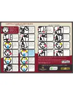
S14
Brand: Caffitaly System Pages: 2
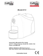
S14
Brand: Caffitaly System Pages: 12
V1.0
Brand: La Marzocco Pages: 64
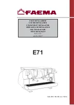
E71
Brand: Faema Pages: 328
NC-ZF1
Brand: Panasonic Pages: 44
Exprelia Evo HD8855
Brand: Saeco Pages: 80
GranBaristo HD8966
Brand: Saeco Pages: 96


