KANSAI SPECIAL SX Series, Instructions Manual
The GE SX Series installation and operation manual is your comprehensive guide to efficiently setting up and running your product. This essential manual is available for free download at manualshive.com, providing users with easy access to the crucial instructions they need to get the most out of their GE SX Series product.
Share
Download


Reviews:
No comments
Related manuals for SX Series

C3000
Brand: Xerox Pages: 298

7310000
Brand: Clarke Pages: 4

DK 2500
Brand: Titan Pages: 33

CONTEC HORNET
Brand: Bartell Pages: 20
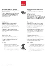
202-082-204
Brand: ELNA Pages: 2

DC2011
Brand: Janome Pages: 94

ECO-C Binder 2:1 Pitch
Brand: Officezone Pages: 5

KM 150/500 R D 4W
Brand: Kärcher Pages: 420

FOG1500
Brand: involight Pages: 58

Minoltafax 1600e
Brand: Konica Minolta Pages: 127

DDL-5530
Brand: JUKI Pages: 36

HZL-27Z
Brand: JUKI Pages: 48

MS-201
Brand: Easy@Home Pages: 86

COTI
Brand: CPI Pages: 170

KM 100
Brand: Tornado Karcher Pages: 17

IA 9100
Brand: Electrothermal Pages: 40

aquamat 75
Brand: Taski Pages: 22

magicolor 2490MF
Brand: EDNord Pages: 86


