K-Rain PRO-LC, Installation, Programming, And Operation Manual
The K-Rain PRO-LC is a cutting-edge irrigation controller designed to simplify the management of your sprinkler system. Ensure a hassle-free installation and optimize functionality with our comprehensive Installation, Programming, and Operation Manual. Download this essential manual free of cost from manualshive.com to unlock the full potential of your K-Rain PRO-LC.
Share
Download


Reviews:
No comments
Related manuals for PRO-LC

NW-1000
Brand: NatureWater Pages: 10

guide + play GPS-500
Brand: Harman Kardon Pages: 10

HydroTap
Brand: Zip Pages: 7

Reflexomat
Brand: Reflex Pages: 26

WD-UB system
Brand: Waterdrop Pages: 2

UV-C Unit 18 Watt
Brand: velda Pages: 12

MGU
Brand: Alpine Pages: 2
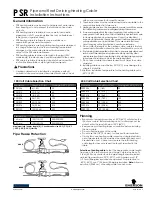
EASYHEAT PSR1006
Brand: Emerson Pages: 5

Keystone OM1 - EPI2
Brand: Emerson Pages: 32

FBxRemote I/O
Brand: Emerson Pages: 36
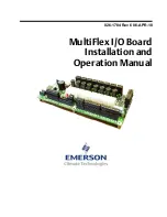
810-3013
Brand: Emerson Pages: 36

PA203
Brand: Power Dynamics Pages: 16

F3100MBC
Brand: GTO Pages: 2
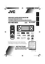
EXAD KD-NX5000
Brand: JVC Pages: 357

SPORTS POD
Brand: HENRY Pages: 3

WRG 35
Brand: Maico Pages: 60

AFS 870-0
Brand: SSS Siedle Pages: 28

TK-CS10
Brand: Panasonic Pages: 4


