SERVICE MANUAL
No. 82829
November 2000
HR-DVS2EK/EU
SPECIFICATIONS
(The specifications shown pertain specifically to the model HR-DVS2EU)
Mini DV/S-VHS VIDEO CASSETTE RECORDER
Printed in Japan
VICTOR COMPANY OF JAPAN, LIMITED
VIDEO DIVISION
S40894
This service manual is printed on 100% recycled paper.
COPYRIGHT © 2000 VICTOR COMPANY OF JAPAN, LTD.
HR-DVS2EK/EU
No. 82829
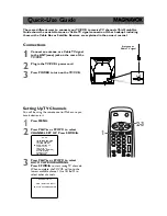
625
TV PR +
TV PR –
T
V
–
TV
+
1
2
3
4
5
6
7
8
9
1
2
1
2
3
VHS
DV
TV
CABLE/SAT
TV/VCR
– –:– –
AUDIO
0000
START
DEBUT
STOP
FIN
DATE
PR
DAILY/QTDN.
VPS/PDC
AUX
WEEKLY/HEBDO
EXPRESS
LCD PROG
0
PROG
OK
3
4
4
MENU
30 SEC
ENTER/ENTREE
DV IN/OUT
ENTREE/SORTIE DV
VHS
DV
A.DUB
INSERT
PR
DUB
COPIE
DV
VHS
START
R.A.EDIT
IN/OUT
S-VHS ET
PULL-OPEN
GENERAL
Power requirement
: AC 220 V – 240 V
`
, 50 Hz/60 Hz
Power consumption
Power on
: 33 W
Power off
: 7.9 W
Temperature
Operating
: 5°C to 40°C
Storage
: –20°C to 60°C
Operating position
: Horizontal only
Dimensions (WxHxD) : 435 mm x 124 mm x 391 mm
Weight
: 6.7 kg
Input/Output
: 21-pin SCART connectors :
IN/OUT x 1, IN/DECODER x 1
RCA connectors:
VIDEO IN x 1, AUDIO IN x 1, AUDIO OUT x 1
S-Video connectors:
IN x 1, OUT x 1
DV connector: IN/OUT x 1
(4-pin, IEEE1394 conformity, digital input/output)
VHS DECK VIDEO/AUDIO
Signal system
: PAL-type colour signal and CCIR monochrome
signal, 625 lines
50 fields
Recording system
: DA4 (Double Azimuth) head helical scan system
Format
: S-VHS/VHS PAL standard
Signal-to-noise ratio
: 45 dB
Horizontal resolution
(SP/LP)
: 250 lines (VHS)
400 lines (S-VHS)
(EP)
: 220 lines (VHS)
350 lines (S-VHS)
Frequency range
: 70 Hz to 10,000 Hz (Normal audio)
20 Hz to 20,000 Hz (Hi-Fi audio)
Maximum recording time
(SP)
: 240 min. with E-240 video cassette
(LP)
: 480 min. with E-240 video cassette
(EP)
: 720 min. with E-240 video cassette
DV DECK VIDEO/AUDIO
Signal system
: PAL-type colour signal, 625 lines
50 fields
Recording system
: Digital Component Recording
Format
: DV format (SD mode)
Cassette
: Mini DV Cassette
Maximum recording time
(SP)
: 60 min. with M-DV60ME cassette
(LP)
: 90 min. with M-DV60ME cassette
Audio recording system
: PCM 48 kHz, 16 bit (2 ch)/
32 kHz, 12 bit (4 ch)
TUNER/TIMER
TV channel storage
capacity
: 99 positions
(+AUX position)
Tuning system
: Frequency synthesized tuner
Channel coverage
: VHF 47 MHz – 89 MHz/
104 MHz – 300 MHz/
302 MHz – 470 MHz
UHF 470 MHz – 862 MHz
Memory backup time : Approx. 60 min.
ACCESSORIES
Provided accessories : RF cable,
21-pin SCART cable,
Satellite Controller RM-SD1,
Infrared remote control unit, "R6"
battery x 2
Specifications shown are for SP mode unless otherwise specified.
E.& O.E. Design and specifications subject to change without notice.
Summary of Contents for HR-DVS2EK
Page 5: ......
Page 41: ...2 20 ...