


.
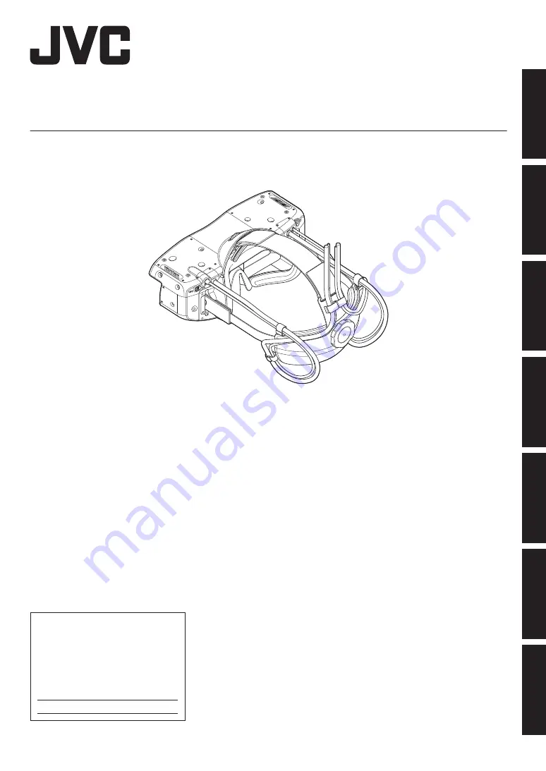
Head Mounted Display
HMD-VS1W
.
Thank you for purchasing this JVC product.
Please read this “INSTRUCTIONS” prior to use to ensure proper use of this unit.
Be sure to read the (pages P. 4 to P. 8
)
especially for safe use of this unit.
.
For Customer use :
Enter below the serial No. which is
located on the body.
Retain this information for future
reference.
HMD-VS1W
Model No.
Serial No.
INSTRUCTIONS
%$
Getting Started
Set up
Operate
Adjust/Set
Maintenance
Troubleshooting
Others


