


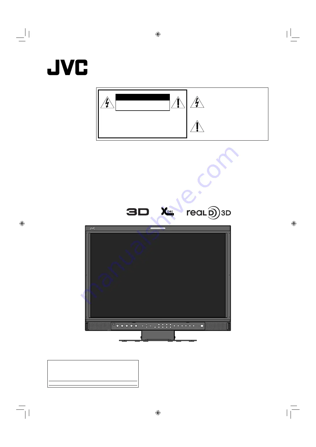
MULTI FORMAT 3D LCD MONITOR
DT-3D24G1
INSTRUCTIONS
LCT2655-001A-H
For Customer Use:
Enter below the Serial No. which is located on the rear of
the cabinet. Retain this information for future reference.
Model No. :
DT-3D24G1
Serial No. :
CAUTION:
To reduce the risk of electric shock. Do
not remove cover (or back). No user
serviceable parts inside. Refer servicing
to qualified service personnel.
RISK OF ELECTRICAL SHOCK
DO NOT OPEN
The lightning flash with arrowhead
symbol, within an equilateral triangle is
intended to alert the user to the presence
of uninsulated “dangerous voltage”
within the product’s enclosure that may
be of sufficient magnitude to constitute a
risk of electric shock to persons.
The exclamation point within an
equilateral triangle is intended to alert
the user to the presence of important
operating and maintenance (servicing)
instructions in the literature
accompanying the appliance.
CAUTION
DT3D24G1̲EN.indb 1
DT3D24G1̲EN.indb 1
11.1.25 0:53:40 PM
11.1.25 0:53:40 PM


