QFX10002
See the complete QFX Series documentation at
http://www.juniper.net/techpubs/.
To install and configure any model of the Juniper Networks
QFX10002 switch, you need:
z
Either an electric lift or two people to lift the switch into place. An
additional person is needed for securing the switch to the rack.
z
Electrostatic discharge (ESD) grounding strap (not provided).
z
One pair of front-mounting rails (provided).
z
One pair of rear-mounting blades (provided).
z
Twenty-four flat-head M4x6-mm Phillips mounting screws to secure the mounting rail
to the chassis (provided).
z
Sixteen screws to secure the chassis and mounting blades to the rack (not provided).
z
Screwdriver appropriate for your rack mounting screws (not provided).
z
Two power cords with plugs for QFX10002-36Q and four power cords with plugs for
QFX10002-72Q that are appropriate for your geographical location (provided).
z
RJ-45 cable and RJ-45 to DB-9 serial port adapter (provided).
z
Management host, such as a PC laptop, with a serial port (not provided).
z
(Optional) Grounding cable kit with bracket, lug, and three nuts with integrated
washers.
Part 1: Mount the Switch
The QFX10002 can be mounted in a four-post rack configuration. To mount the device in
a standard 19 inch rack:
1. Attach the ESD grounding strap to your bare wrist and to a site ESD point.
NOTE:
If you are mounting multiple units in the rack, mount the heaviest unit at the
bottom and mount the others from bottom to top in order of decreasing weight. The
QFX10002-72Q weighs 68.6 lbs (31.1 kg) and the QFX10002-36Q weighs 54 lbs
(24.5 kg). Installing the QFX10002 switch in a rack or cabinet requires either a
mechanical lift or two people to lift the switch and another person to secure it to the rack.
2. Place the rack in its permanent location, allowing adequate clearance for airflow and
maintenance, and secure it to the building structure.
3. Decide whether the field replaceable unit (FRU) end of the switch or the port end is to
be placed at the front of the rack. Position the switch in such a manner that the
AIR OUT
labels on components are next to the hot aisle.
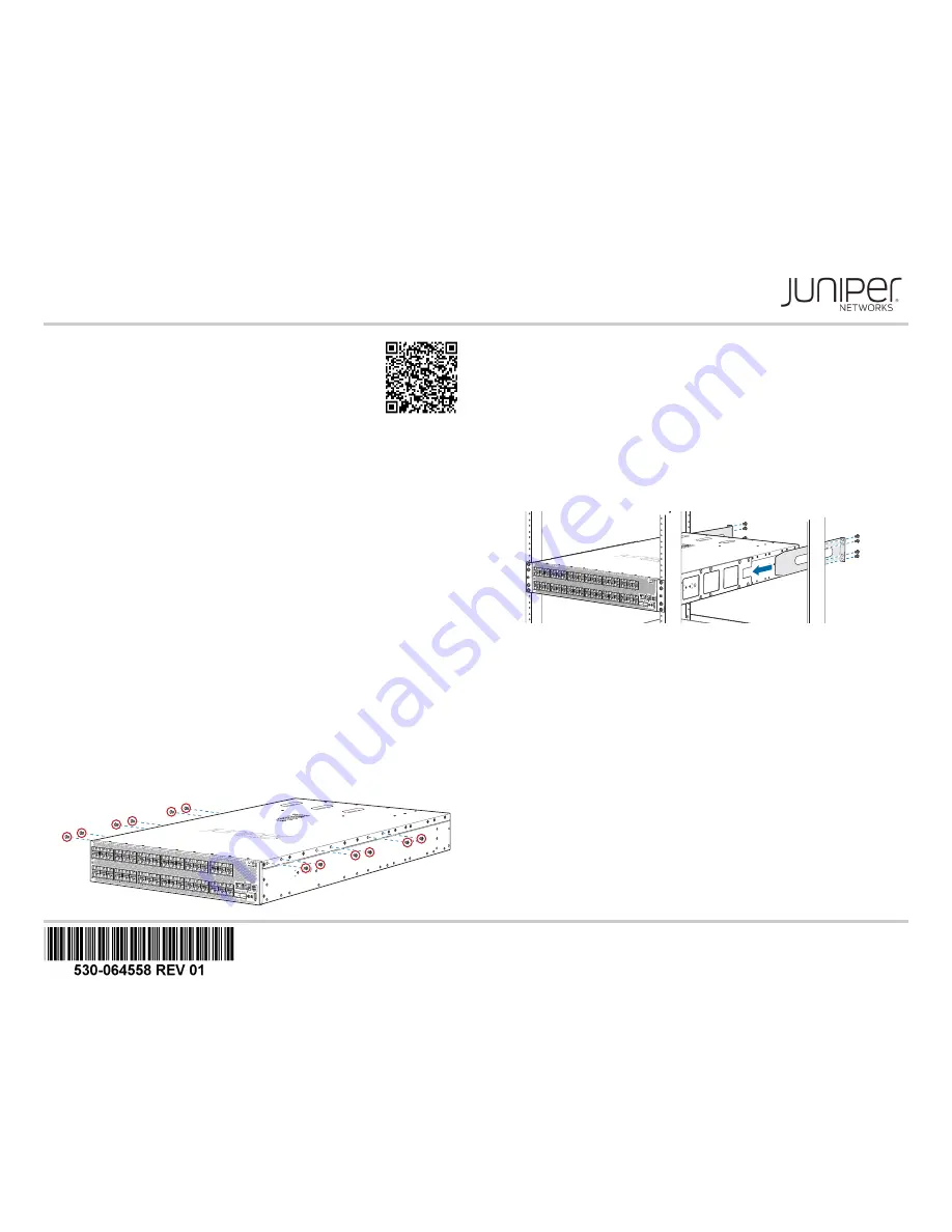
4. Using a Philips screwdriver, remove the six screws on each side of the chassis that
hold the cover to the chassis.
5. Align the holes in the mounting rail with the holes on one side of the chassis.
6. Attach the mounting rail to the switch using 11 mounting screws. Tighten the screws.
7. Repeat Step 5 and Step 6 on the opposite side of the switch.
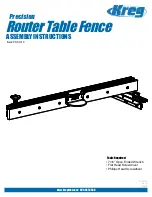
8. Either use a mechanical lift or have two people grasp both sides of the switch, lift it,
and position it in the rack so that the front bracket is aligned with the rack holes.
9. Have another person secure the front of the switch to the rack using eight mounting
screws (and cage nuts and washers if your rack requires them.) Tighten the screws.
10. Continue to support the switch while sliding the rear-mounting blades into the
channel of the side-mounting rails and securing the blades to the rack. Use the eight
mounting screws (and cage nuts and washers if your rack requires them) to attach to
the blade to the rack. Tighten the screws.
11. Ensure that the switch chassis is level by verifying that all the screws on the front of
the rack are aligned with the screws at the back of the rack.
12. Attach a grounding cable to earth ground and then attach it to the chassis grounding
points.
Part 2: Connect Power to the Switch
The switch is supplied with either two or four factory-installed power supplies.
To connect power to an AC-powered switch:
1. If the AC power source outlet has a power switch, set it to the OFF (0) position.
2. Insert the coupler end of the power cord into the AC power cord inlet on the AC
power supply faceplate.
3. Push the power cord retainer onto the power cord.
4. Insert the power cord plug into the power source outlet.
5. If the AC power source outlet has a power switch, set it to the ON (|) position.
6. Verify that the AC or the DC LED is lit green and on steadily.
Part 3: Perform the Initial Configuration
You must perform the initial configuration of the switch through the console port. Before
you begin, set the following parameter values from the console server or PC:
z
Baud Rate—9600
31
g05039
7