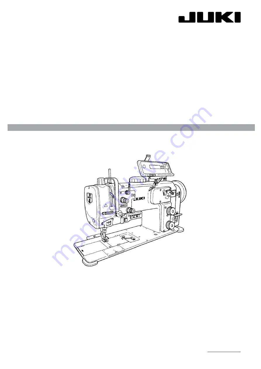
background image

29227501

No.E306-04

ENGINEER’S MANUAL

1-NEEDLE, HIGH-SPEED, UNISON-FEED LOCKSTITCH MACHINE WITH VERTICAL-AXIS LARGE HOOK
AND AUTOMATIC THREAD TRIMMER

LU-2210N-7

LU-2210W-7

®

1- NEEDLE, HIGH-SPEED, UNISON-FEED LOCKSTITCH MACHINE WITH VERTICAL-AXIS LARGE HOOK
AND AUTOMATIC THREAD TRIMMER (2P DIAL)

LU-2212N-7

2- NEEDLE, HIGH-SPEED, UNISON-FEED LOCKSTITCH MACHINE WITH VERTICAL-AXIS LARGE HOOK
AND AUTOMATIC THREAD TRIMMER

LU-2260N-7

LU-2260W-7

1- NEEDLE, HIGH-SPEED, UNISON-FEED LOCKSTITCH MACHINE WITH VERTICAL-AXIS LARGE HOOK
AND AUTOMATIC THREAD TRIMMER (NEEDLE THREAD CLAMP DEVICE/2P DIAL)

LU-2220N-7

Summary of Contents for LU-2210N-7

Page 1: ...ISON FEED LOCKSTITCH MACHINE WITH VERTICAL AXIS LARGE HOOK AND AUTOMATIC THREAD TRIMMER 2P DIAL LU 2212N 7 2 NEEDLE HIGH SPEED UNISON FEED LOCKSTITCH MACHINE WITH VERTICAL AXIS LARGE HOOK AND AUTOMATIC THREAD TRIMMER LU 2260N 7 LU 2260W 7 1 NEEDLE HIGH SPEED UNISON FEED LOCKSTITCH MACHINE WITH VERTICAL AXIS LARGE HOOK AND AUTOMATIC THREAD TRIMMER NEEDLE THREAD CLAMP DEVICE 2P DIAL LU 2220N 7 ...

Page 2: ...e Change for Adjustment and the roles of each component are described these are not included in the instruction manual When maintenance is performed for our sewing machines refer not only to this manual but also to the instruction manual and parts list This engineer s manual describes the basic adjusting values as the reference values in the first page and the observed events caused by sewing and ...

Page 3: ... Upper Feed Timing 24 4 Height of the Feed Dog 26 5 Amount of alternating vertical movement of the walking foot and presser foot Balance between the lifting amounts of the presser foot and walking foot 28 7 Adjustment of the Feed Mechanism 30 1 Zeroing of the feed adjusting mechanism 30 2 Stitch length in the normal feed and reverse feed 32 3 2P Adjustment for LU 2212N 7 and LU 2220N 7 34 8 Positi...

Page 4: ...ener 70 1 Timing of the Opener 70 2 Clearance between the opener and the protruding section of the inner hook 70 14 Presser Lifting Unit 72 1 Presser Lifting Amount 72 2 Presser Lifting Cylinder 72 15 Safety Mechanism 74 1 Releasing Torque Adjustment 74 2 How to reset the Safety Mechanism 74 16 Lubricating Unit 76 1 Oil Distribution Diagram 76 2 Supplying and Replacing Oil 76 3 Filter Replacement ...

Page 5: ...mmer only 117 1 Connector from the machine head LU 2210N W 7 LU 2260N W 7 other than LU 22 0 0 0B 117 2 Connectors from solenoid valve asm 40024969 LU 2210N W 7 LU 2260N W 7 other than LU 22 0 0 0B 117 3 Connector from the machine head For LU 2210N W 7 LU 2260N W 7 LU 22 0 0 0B 118 4 Connector from solenoid valve asm 40025724 For LU 2210N W 7 LU 2260N W 7 LU 22 0 0 0B 118 5 Connector from the mach...

Page 6: ...MEMO ...

Page 7: ... with the plunger and felts 26 Lubricating oil JUKI New Defrix Oil No 1 Equivalent to ISO VG7 27 Space under the needle 263 5 mm Distance from the center of the presser bar to the bottom of the arm 28 Bed size 517mm x 178mm 29 Automatic lifter Externally mounted pneumatic cylinder 30 Lifting device DL 31 2P DIAL unit Pneumatic cylinder sheathing system 32 Needle thread clamp device 33 Weight of ma...

Page 8: ...er foot lifter is equipped as standard 15 Option Z Without option A AE9 Bobbin thread level detection device Applicable only for the machine with Hook Code N Large Hook 18 Accessory Specification Code A Standard B For Europe D For United States E For Japan 8 Walking Foot A Standard B For urethane C Right single sided foot D Left single sided foot E For piping ø3 F For piping ø4 G For piping ø5 H F...

Page 9: ...Z Without option A AE9 Bobbin thread level detection device 18 Accessory Specification Code A Standard B For Europe D For United States 8 Walking Foot A Standard B For urethane C Right single sided foot D Left single sided foot E For piping ø3 F For piping ø4 G For piping ø5 H For piping ø6 J Adjustable type for piping ø3 K Adjustable type for piping ø4 L Adjustable type for piping ø5 M Adjustable...

Page 10: ...B 6 0mm C 8 0mm D 10 0mm E 12 0mm J 20 0mm 11 DL Device Z Without DL device A DL device without knee switch B DL device with knee switch The pneumatic automatic presser foot lifter is equipped as standard 15 Option Code Z Without option A AE9 Bobbin thread level detection device Applicable only for the machine with Hook Code N Large Hook 18 Accessory Specification Code A Standard B For Europe D Fo...

Page 11: ...ption A AE12 Bobbin thread level detection device 18 Accessory Specification Code A Standard B For Europe D For United States 8 Walking Foot A Standard B For urethane C Right single sided foot D Left single sided foot E For piping ø3 F For piping ø4 G For piping ø5 H For piping ø6 J Adjustable type for piping ø3 K Adjustable type for piping ø4 L Adjustable type for piping ø5 M Adjustable type for ...

Page 12: ...ming of the opener Refer to 13 Timing of thread trim ming action Refer to 11 8 LU 2212N 7 Range of the upper stop position Timing of thread trimming action Refer to 11 7 LU 2210N W 7 LU 2260N W 7 Feed rock timing Refer to 6 1 Aligning the pointer on the machine arm highest dead point of the needle bar H Direction of rotation L K J H G F E D C B A A B C D E F H G J K L Timing between the needle and...

Page 13: ...t and sewing pitch 1 If the sewing pitch is 6mm or less it shall be within the range between upper and lower limit values Amount of alternating vertical movement mm Max sewing speed rpm 1 to 6 5 2 000 Needle Gauge mm Max Sewing Speed rpm 4 to 10 3 500 12 to 20 3 300 22 to 30 3 000 32 to 36 2 500 Sewing speed rpm Amount of alternating vertical movement mm 2 For sewing pitch of more than 6 mm but le...

Page 14: ... of the operator When tightening the thrust collar set screw tighten it while rocking the needle bar frame toward the side opposite from the operator Needle bar frame driving shaft Assemble the thread take up crankshaft and the thread take up crank with the shaft pressed against the end face of the crank Assemble the thread take up crank and the thread take up crank shaft support so that they can ...

Page 15: ...ch the triangular lever shafts and in place 25 Attach the presser spring regulating arm in place 26 Attach the presser spring regulating arm shaft in place 27 Fasten the set screw of the presser spring regulating arm shaft 28 Attach the presser adjusting spring 29 Attach the presser spring regulating dial in place 30 Set the stitch dial to 0 on the scale 31 Adjust the needle entry in the needle sl...

Page 16: ...r should be brought to the lowest dead point The stitch dial should be set to 0 on the scale The needle feeding arm should be made perpendicular The following clearance should be provided between operator s side end of the slot in the throat plate and the edge of the feed dog 5 7 0 2 mm LU 2210N W 7 LU 2212N 7 4 2 0 2 mm LU 2260N W 7 For all gauge sizes Needle bar frame driving link 90 Needle feed...

Page 17: ... The feed amount of the needle is mechanically larger than the feed amount of the feed dog by 5 o If the needle entry is adjusted too close to the operator 1 The needle may interfere with the feed dog resulting in needle breakage o If the needle entry is adjusted too far from the operator 1 When the needle comes out of the slot in the throat plate the needle may interfere with the feed dog resulti...

Page 18: ...U 2220N 7 Needle Entry Point Position where the distance between presser bar and upper feed bar becomes 10 2 0 1mm Requirements Hand wheel graduation A coincides with the upper surface of hand wheel indicator Standard feed dial graduation 0 The needle feed arm is positioned perpendicular Needle bar frame driving link 90 Needle feeding arm ...

Page 19: ...sure that the bottom face of the knee lifter arm A is en gaged with the presser lifting lever 10 Attach the aperture plate in place Caution The feed amount of the needle is mechanically larger than the feed amount of the feed dog by 5 o If the needle entry is adjusted too close to the operator 1 The needle may interfere with the feed dog resulting in needle breakage o If the needle entry is adjust...

Page 20: ...op end of the needle eye and the blade point of the hook when the needle bar is raised from its lowest dead point by 2 0 0 2 mm Reference The needle bar lowest dead point is where the lower face of needle bar frame is aligned with the upper marker line engraved on the needle bar 2P stitch dial For LU 2212N 7 and LU 2220N 7 Blade point of the hook Needle eyelet 2 0 0 2mm 1 4 0 2mm Marker lines engr...

Page 21: ... screw 4 Adjust the height of the needle bar to the specified dimension 5 Fasten the needle bar connecting stud clamping screw o Stitch skipping or thread breakage may result 4 At that time align the bottom face of the needle bar frame with the marker line engraved on the needle bar the upper one of the two marker lines This will en able you to adjust the height of the needle bar almost to the spe...

Page 22: ...tive amount of the needle guard 0 15 to 0 2 mm The stitch dial should be set to 0 on the scale Blade point of the hook The needle guard does not work The needle guard works Hook driving shaft set collar Hook driving shaft coupling Hook driving shaft 2 5 0 3mm 2 5 0 3mm A 2 5 0 3mm B C D 0 05 to 0 1mm Blade point of the hook Needle guard 0 15 to 0 2mm Blade point of the hook 0 to 0 05mm LU 2210N W ...

Page 23: ...by fastening the set screws and in the hook driving shaft saddle in the written order 8 Turn the needle holder effectiveness adjusting screw and adjust the effectiveness value to 0 15 to 0 2mm until the gap between the needle and the hook blade point is adjusted to 0 05 0 1mm 9 At this time confirm that the clearances A B C and D in the hook driving shaft coupling are respectively adjusted to 2 5 ...

Page 24: ...ld point Graduation L on the hand wheel The stitch dial should be set to 0 on the scale The adjustment should be performed after the needle bar has been adjusted to the correct height Graduation L on the hand wheel Pointer on the hand wheel Hand wheel Reverse feed lever 1 4 0 2mm 2 0 0 2mm Blade point of the hook Center of the needle Lower shaft Lower shaft coupling L ...

Page 25: ...ook is aligned with the center of the needle 5 Fasten the set screw Caution Adjust the needle entry in the needle slot of the feed dog with reference to the feeding direction prior to the adjustment of Timing between the needle and the hook o Loose stitches stitch skipping or thread breakage may result 3 Refer to 3 1 Types and Names of Graduations on the Hand wheel 5 Hold the hook by hand at the c...

Page 26: ...r Standard Adjustment o Hook Shaft Thrust Plate Thickness mm Part No Engraved mark 1 4 10111201 4 1 5 10109809 5 1 6 Standard 10112506 6 1 7 10112605 7 1 8 10112704 8 0 9 0 1mm Throat plate Inner hook stopper Inner hook stopper Hook shaft bearing Direction of rotation ...

Page 27: ... Then fasten the set screw No 2 in terms of the direction of rotation of screws 3 For how to adjust the thread trimmer after the completion of the ad justment of the clearance between the throat plate and the inner hook stopper refer to 3 10 11 and 12 Thread Trimmer Device o If the clearance between the throat plate and the inner hook stopper is too large The inner hook may come off the throat pla...

Page 28: ...hen the hand wheel pointer is aligned to the graduation B on the hand wheel the set screw No 1 in terms of the direction of rotation on the feed rock cam is nearly brought to the top 2 Vertical Feed Timing Adjust so that the mark marker dot engraved on the end face of the feed rock cam on the feed rock cam is in line with the mark marker dot engraved on the feed driving cam Then fasten the set scr...

Page 29: ...n the Vertical Feed Cam Cautions 1 Take care not to allow any such foreign matter as a screw to enter the bed tank 2 Adjust the timing within the range of 5 from the standard timing o Improper stitch length may result when the machine is operated at high low speed o Thread tension may change from the correct one o Tightness of normal and reverse stitches may be different from each other 4 Refer to...

Page 30: ...dard Adjustment 3 Upper Feed Timing Set marker dot engraved on the periphery of the main shaft in line with the set screw No 1 of the upper feed cam and fasten the set screws No 1 and No 2 Main shaft 0 5mm A B ...

Page 31: ...llow any foreign matter such as a screw to enter the arm 2 Adjust the timing within the range of 5 from the standard timing o Improper stitch length may result when the machine is operated at high low speed o When the upper feed cam is turned toward the operator in the direction of arrow A the upper feed timing will be earlier than the standard timing When the upper feed cam is turned away from th...

Page 32: ... of the feed dog 0 5 to 0 6 mm Requirements Set the stitch dial to 6 on the scale Align the hand wheel pointer with the graduation L on the hand wheel Throat plate 0 5 to 0 6mm Graduation L on the hand wheel Hand wheel pointer Hand wheel L Vertical feed arm ...

Page 33: ...f the feed dog to 0 5 to 0 6 mm 5 Loosen the vertical feed arm tightening screw Caution Fasten the clamping screw with a tightening torque of 5 88 to 6 86N m 60 to 70 kgf cm If the height of the feed dog is excessive o The material may be fed back ward in the normal feed mode If the height of the feed dog is insuf ficient o The stitch length may become shorter than the specified value 3 Refer to 3...

Page 34: ...rnat ing vertical movement of the walking foot and presser foot should be set to 1 The stitch dial should be set to the maxi mum value on the scale The sole of the presser foot should rest on the throat plate Make the walking foot come in contact with the feed dog The upper feed timing has already been properly adjusted before the adjustment of the amount of alternating vertical move ment of the w...

Page 35: ...scribed in step 5 make the walking foot rest on the feed dog and make the presser foot come in contact with the throat plate 7 Fasten the upper feed cam clamping screw o Improper stitch length may result when the machine is operated at high low speed o The lifting amount of the presser foot or the walking foot would be decreased As a result the ma terial may not be fed smoothly 5 If the graduation...

Page 36: ...eed ad justing eccentric pin faces in the same direction as the slot in the feed adjustment change arm Tilt the feed change belt in the direction of C or D until the feed amount of the feed dog becomes zero 0 At that position fas ten the set screw Align the marking of the face aperture plate on the front face of the machine with 0 on the scale of the stitch dial Level H Level L Slot Marking chamfe...

Page 37: ... the feed dog is set to zero 0 7 Fasten the clamping screw in the feed adjustment change arm Caution Fasten the screw with a tightening torque of 3 43 to 4 41N m 35 to 45 kgf cm 8 Supply oil to the machine Check it through the oil sight window 9 Loosen the set screw of the stitch dial 10 Align zero 0 on the scale of the stitch dial with the marking on feed aperture plate of the front face of the m...

Page 38: ...e marking is tilted in the direction of arrow A The stitch length of the normal feed stitching will decrease The stitch length of the reverse feed stitching will increase If the marking is tilted in the direction of arrow B The stitch length for the normal feed stitching will increase The stitch length of the reverse feed stitching will decrease Marking chamfered Slot A B To improve ease of operat...

Page 39: ...d adjusting eccentric pin o The stitch length specified may not be equally obtained in the normal feed stitching and the reverse feed stitching resulting in excessive stitch length error between the normal feed stitching and the reverse feed stitching 5 Turning the feed adjusting ec centric pin downward in the direction of arrow A decreases the stitch length for the normal feed stitching and incre...

Page 40: ... 34 3 2P Adjustment for LU 2212N 7 and LU 2220N 7 How to zero for the 2P adjustment Standard Adjustment Point zero Origin position To be matched Fig A Fig B Fig C LU 2212N 7 LU 2220N 7 ...

Page 41: ... dial screw is aligned with the 2P feed regula tor the point zero position for the 2P adjustment would be shifted 9 Loosen the 2P stitch dial set screw 10 Turn the 2P stitch dial counterclockwise to align with the dial stopper position 11 Fasten 2P stitch dial setscrew Confirmation 1 Perform the above adjusting procedure steps No 1 through 4 2 Turn the 2P stitch dial counterclockwise and set it at...

Page 42: ...ed Connecting Arm the amount of condensation Requirement The stitch dial should be set to the maxi mum value on the scale Standard Adjustment 0 5 to 1 5 m m 11 5 0 5mm LU 2210N W 7 LU 2260N W 7 and LU 2212N 7 LU 2220N 7 Standard 12mm ...

Page 43: ... condensation is reduced o Increase it by 12mm or more The amount of condensation is increased 3 After adjustments tighten the fixing nut 4 After the adjustment of the amount of condensation check the position of the reverse feed lever Caution When the amount of condensation is reduced the residual thread length on cloth side becomes shorter However if this amount is too small the material cloth m...

Page 44: ...tate Caution The above figure is illustrated as seen from the rear side of the machine head with the face aperture plate on the front of the machine head removed A Bobbin winder unit is in the re set state Bobbin winder unit is in the set state Bobbin presser spring B Standard Adjustment ...

Page 45: ... shaft to the bobbin presser to 25 5 0 5 mm 5 Fasten the set screw of the bobbin winder cam 6 Attach the face aperture plate to the front of the machine head 7 Operate the sewing machine to perform bobbin winding 8 Securely fasten the hexagon nut 3 For how to remove the aperture plate of LU 2212N 7 and LU 2220N 7 refer to 17 and 18 Aperture Plate Removal Procedure for LU 2212N 7 and LU 2220N 7 8 I...

Page 46: ... Arms A B and C 10 Thread Trimmer Device for LU 2210N W 7 and LU 2260N W 7 5 5 t o 6 5 m m 23 6mm A B Model Dimension A mm LU 2210N 7 LU 2260N 7 LU 2210W 7 LU 2260W 7 5 2 4 8 1 5 to 1 7mm 0 5mm E F A D C B Counter knife gauge 23 6mm Throat plate 1 5 to 1 7mm A B Standard Adjustment ...

Page 47: ...he main body of the solenoid and fasten the clamping screws of the moving knife driving arms B and C 3 Adjust so that a clearance of 0 2 mm is provided between the thread trimmer cam and the thread trimmer cam roller when the thread trimmer cam is brought to the highest position of its stroke for both the right hand and left hand side hooks 4 Fasten the clamping screw of the moving knife driving a...

Page 48: ...knife blade tip Standard initial position Initial position for thick thread Align the end of the counter knife base with the end of the counter knife gauge Standard Adjustment 4 1 0 1mm A Attach the counter knife and clamp screw while they are contacted onto the staged section of the counter knife base 0 2mm 17 5 mm 0 0 2 Bed slide plate groove end Throat plate 33 0 1mm 1 mm 0 0 1 6 to 7 m m ...

Page 49: ... make the sewing machine perform thread trimming and align the top end of the moving knife with the top end of the counter knife This is the initial position of the thread trimming mechanism At this time confirm that a clearance of 0 05 to 0 15 mm is provided between the plunger stopper of the thread trimmer solenoid and the main body of the thread trimmer solenoid o If the distance 17 5 mm from t...

Page 50: ...ead by one turn 5 Height of the Moving Knife LU 2210N W 7 LU 2212N 7 and LU 2260N W 7 for the right hand side hook 0 3 to 0 4mm LU 2212N 7 0 4 to 0 5mm LU 2210N W 7 LU 2260N W 7 Standard Adjustment Thread trimmer cam ...

Page 51: ... the thread trimmer solenoid to the terminal board 14 Connect the urethane tubes to the tube connecting screws of the hook shaft saddle At the same time use the tube connecting screws to which the urethane tubes had been connected be fore removing it 15 Adjust the clearance between the needle and the blade point of the hook Refer to 3 4 2 Clearance between the Needle and the Blade Point of the Hoo...

Page 52: ... 46 6 Height of the Moving Knife LU 2260N W 7 for the left hand side hook 0 4 to 0 5mm Standard Adjustment ...

Page 53: ...g knife shaft up and down 5 Fasten the set screws 2 pcs of the moving knife shaft thrust collar 6 Fasten the clamping screw of the moving knife driving arm C and the clamping screw of the moving knife driving arm A Refer to 3 10 4 Moving Knife Driving Arms A B and C o If the clearance between the moving knife and the bobbin case is too large The needle thread and the bob bin thread may fail to be ...

Page 54: ...Cam for LU 2210N W 7 and LU 2260N W 7 Thread eyelet of the moving knife Thread Tetron 8 Front end of the moving knife Graduation D on the Hand wheel Hand wheel pointer Reverse direction Normal direction Standard Adjustment ...

Page 55: ...he moving knife driving arm A turn the hand wheel until the hand wheel pointer meets the graduation D on the hand wheel 9 In the state described in step 8 turn the thread trimmer cam until it slightly comes in contact with the thread trimmer cam roller of the moving knife driving arm A 10 Fasten the set screw of the thread trimmer cam 11 Make sure that the timing of thread trimming action has been...

Page 56: ... 50 8 Thread Trimmer Cam for LU 2212N 7 Graduation J on the hand wheel Hand wheel pointer Reverse direction Normal direction J Forwarding direction Section R Standard Adjustment ...

Page 57: ... cam set screw 5 Make the section R of the thread trimmer cam come in close contact with the thread trimmer cam roller 6 Fasten the thread trimmer cam set screw 7 Make sure that the hand wheel pointer meets the graduation J on the hand wheel when the section R of the thread trimmer cam comes in close contact with the thread trimmer cam roller Adjustment Procedure Results of Improper Adjustment 2 F...

Page 58: ...ing the sequential order instructed in this manual Otherwise the result will be different from that of regular adjustments Before the adjustment of the thread trimming device check the mounting position of the feed dog There are adjusting points according to the feed dog standard Refer to 3 3 2 Needle entry in feeding direction in regard to the feed dog hole 1 Positioning for the thread trimming c...

Page 59: ...d trimming cylinder joint 2 Adjust the size of the thread trimming cylinder joint and the thread trimming cylinder to 7 0 0 5mm 3 Tighten the fixing nut of the thread trimming cylinder joint Adjustment Procedure Results of Improper Adjustment ...

Page 60: ... 54 2 Counter knife adjustment of movement Positioning for the counter knife base stopper Contact Grooves of face plates Top surface of the bed 9 0 0 5mm 37 8 0 1mm 37 8 0 1mm Standard Adjustment ...

Page 61: ...of 4 above 37 8 0 1mm is maintained keep a contact between the counter knife base and the counter knife base stopper and fix the counter knife base stopper 6 While the state of 4 above 37 8 0 1mm is maintained adjust the gap to 9 0 0 5mm between the thread trimming cylinder joint and the joint stopper This shall be done manually At that time it is possible to use an accessory adjusting gauge 7 Tig...

Page 62: ... 56 3 Counter knife adjustment of right and left positioning When mounting the counter knife keep it pressed against the counter worker side and tighten the setscrew 2 4 0 15mm Standard Adjustment ...

Page 63: ...means of the counter knife setscrew In this case keep the counter knife lightly pressed against the counter worker side and tighten the counter knife setscrew 5 Unlock the manual switch of the solenoid valve that has been actuated Refer to 3 12 13 Description of the solenoid valve Confirmation After adjustments in regard to this item right and left positioning for the counter knife manually actuat...

Page 64: ... 58 4 Moving knife adjustment of vertical positioning 0 5 to 0 6mm Coincidence with top surface of the moving knife Standard Adjustment 5 Counter knife adjustment of vertical positioning ...

Page 65: ...nd the thrust collar setscrew When tightening the moving knife driving arm tightening screw follow the adjusting procedures of 7 8 9 and 10 to be described later 5 Counter knife adjustment of vertical positioning 1 Loosen the counter knife base tightening screw and let the upper blade end of the counter knife coincide with the upper surface of the moving knife In this case pay attention to hook s ...

Page 66: ... 60 6 Thread guide mounting position Coincidence of upper surface with the moving knife 7 Adjustment of knife pressure 29 to 30mm Standard Adjustment ...

Page 67: ... 5 Unlock the manual switch of the solenoid valve that has been actuated Turning the hand wheel slowly bay hand take out the thread trimming cam rollers from the cam groove of the thread trimming cam 1 If the knife pressure seems to be weak lightly press the moving knife against the counter knife at the time of adjustments according to 4 above and tighten the moving knife setscrew If the knife pre...

Page 68: ...g knife driving arm and initial position of the moving knife Top surface of the bed Cam groove 26 8 0 1mm 0 05 to 0 15mm Outer periphery of the thread trimming cam 26 8 0 1mm Face plate groove Standard Adjustment ...

Page 69: ... and the outer periphery of the thread trimming cam Then adjust the moving knife to its initial position The initial position of the moving knife is defined when the distance is 26 8 0 2mm between tip of the moving knife and the bed groove At that time it is possible to use an accessory adjusting gauge 6 While the state of 5 above is maintained tighten the moving knife driving arm tightening screw...

Page 70: ...rance between the moving knife drive arm stopper screw and the moving knife drive arm stopper shall be 0 05 to 0 1 mm The return pin and the moving knife return plate shall keep contact with each other Hand wheel indicator Hand wheel graduations Cam groove Contact 0 05 to 0 15mm 0 05 to 0 1mm Standard Adjustment 11 Adjustment of timing for the thread trimming cam ...

Page 71: ...id valve that has been actuated as per 3 herein Caution If a machine lock occurs in the middle of thread trimming confirm the adequacy of adjusting values specified in 3 12 8 3 12 9 and 3 12 10 If any inadequacy is discovered readjustments are required 11 Adjustment of timing for the thread trimming cam 1 Let the sewing machine fall down and loosen the thread trimming cam setscrew 2 Turn the hand ...

Page 72: ... 66 12 Clamp spring mounting position 43 0 to 43 5mm Contact When the moving knife advances to the extreme far end it shall not contact the clamp spring 43 0 to 43 5mm Standard Adjustment ...

Page 73: ...for thin threads the adjusted value shall be 43 5mm so that the clamp spring is made to contact the side surface of the moving knife strongly Confirmation Examine the following two points when the clamp spring is mounted 1 No contact between the clamp spring and the hook 2 No contact with the clamp spring when the moving knife has advanced to the extreme far end If positioning for the clamp spring...

Page 74: ...al switch When the switch in green is pressed inside the cover the solenoid valve can be operated manually The switch can be locked by turning the switch in the direction of the arrow while it is kept pressed The switch can be unlocked by turning it in the opposite direction of the arrow Standard Adjustment ...

Page 75: ...resser foot lowered 9 DL Cylinder protruded B C 2P B C When the power supply is turned ON confirm that all solenoid valve covers are closed In the state that the manual switch is locked the covers cannot be closed In other words this method is effective in avoiding misoperation of the solenoid valve Solenoid valve number symbol Adjustment Procedure Results of Improper Adjustment ...

Page 76: ...inst the in ner hook resting groove on the throat plate Hand wheel pointer Graduation J on the hand wheel Throat plate Backward end of the opener Forward end of the opener Retard Advance Slot Requirements For LU 2210N W 7 LU 2212N 7 and LU 2220N 7 The opener should be brought to its forward end when the hand wheel pointer meets the graduation J on the hand wheel For LU 2260N W 7 The opener should ...

Page 77: ...t that time be sure to loosen the screw with the opener positioned at its backward end 3 Turn the inner hook in the direction of arrow C and press the inner hook stopper against the inner hook resting section of the throat plate 4 Move the opener and adjust so that a clearance of 0 1 to 0 3 mm is provided between the opener and the triangular projection of the inner hook 5 Fasten the opener set sc...

Page 78: ... 2 Presser Lifting Cylinder 21 7 mm 0 0 3 As viewed from the Side 2 Arm Knee lifter spring 1mm 9 6 1 8 mm Manual operation Presser foot Throat plate 15 5 mm Automatic Presser foot Throat plate As viewed from the Hand wheel Side 1 0 0 8 1 0 0 8 1 0 8 m m 19mm At the time when the presser foot is lifted by 15 5 mm ...

Page 79: ...the presser lifting guide bracket In this state fasten the presser lifting bracket clamping screw 2 Presser Lifting Cylinder 1 Loosen the locknut of the cylinder connecting screw 2 Adjust so that the distance from the top end of the rod of the presser lifting cylinder to the center of the cylinder connecting screw is 21 7 mm 3 Fasten the locknut of the cylinder connecting screw Caution When mounti...

Page 80: ...Releasing Torque Adjustment 2 How to reset the Safety Mechanism 15 Safety Mechanism Torque P N x L m L P A Standard Adjustment Standard specification of the releasing torque 11 76 to 14 7N m 120 to 150kgf cm ...

Page 81: ...ng belt on the lower sprocket 2 How to reset the Safety Mechanism If an excessive load is applied to the hook driving shaft the safety clutch will be released In this case the hook will not rotate even if the hand wheel were turned 1 Reset the safety mechanism with the machine head tilted 2 Insert the screwdriver medium supplied with the machine into the hole A in the safety clutch bushing 3 Hold ...

Page 82: ... LU 2210N W 7 LU 2212N 7 LU 2220N 7 LU 2260N W 7 Z To supply oil to the face plate components Oil wick Return oil wick As viewed from side Z 5 to 7mm Standard Adjustment 1 Oil Distribution Diagram 2 Supplying and Replacing Oil ...

Page 83: ... oil to spout from the oil reservoir 3 Observe the oil flow in the urethane tube from the lower section of the bed to check whether or not oil is fed to the hook driving shaft saddle and then circulated 4 Carefully observe the filter to check whether or not oil changes in color due to oxidation and deterioration If oil changed in color obviously replace the deteriorated oil with new oil without de...

Page 84: ...ocedure 4 Adjusting the amount of oil in the hook and cleaning the hook filter 25mm A piece of paper Requirement Operate the sewing ma chine for 5 seconds at the speed of 3 500 rpm Set screws Set screws O ring Standard Adjustment ...

Page 85: ...ed and the amount of oil in the hook will no longer be ad justed So take the greatest care How to clean the Filter in the Hook If the filter is clogged the machine cannot be oiled So it is neces sary to clean the filter periodically Clean the filter following the proce dure described below 1 Remove the hook from the main unit of the sewing machine Loosen the oil amount adjusting screw and take out...

Page 86: ... Plate Removal Procedure for LU 2212N 7 Standard Adjustment 1 Removal Procedure of Aperture Plate 2 Attachment Procedure of Aperture Plate 3 Adjustment of 2P Cylinder Connecting Link Notch Center of Fulcrum Shaft A B ...

Page 87: ...en the cylinder set plate set screw 5 Attach the 2P cylinder temporarily with the 2P cylinder set screw 6 Adjust the conversion link base and attach it so that the 2P cylin der connecting link is parallel with the shaft center of the 2P cylin der Then fasten the conversion link base set screw and fas ten the 2P cylinder set screw 7 Fasten the conversion link hinge screw 3 Adjustment of 2P Cylinder...

Page 88: ... Plate Removal Procedure for LU 2220N 7 Standard Adjustment 1 Removal Procedure of Aperture Plate 2 Attachment Procedure of Aperture Plate 3 Adjustment of 2P Cylinder Connecting Link Notch Center of Fulcrum Shaft A B ...

Page 89: ... the direction of the main shaft and the cylinder connecting lever is in parallel to the shaft core of the reverse cylinder In this state tighten the cylinder mounting plate setscrews 6 Temporarily fasten the 2P cylinder by means of the 2P cylinder setscrews four locations 7 Adjust the conversion link base so that the 2P cylinder connecting link is in parallel to the shaft core of the 2P cylinder ...

Page 90: ...witch B A Pressing the knee switch changes the stitch length from 9 to 6 Standard Adjustment LU 2210N W 7 LU 2260N W 7 LU 2212N 7 Needle thread clamp switch LU 2220N 7 Example Set the stitch dial to 9 on the scale Pressing the switch returns the stitch length of 6 to 9 OFF ON ON OFF LU 2220N 7 ...

Page 91: ...pointer shows the graduation B on the hand wheel 5 2P Switch For the LU 2212N 7 LU 2220N 7 Pressing this switch changes the stitch length to the one specified on the scale of the 2P stitch dial The lamp embedded in the button is turned on For the LU 2220N 7 the upper LED of the switch is lit in the state of switch ON Caution The value specified on the scale of the 2P stitch dial should be smaller ...

Page 92: ...Needle Clamp LU 2260N W 7 A Hole for presser adjusting dial Hole for pulling out the needle bar Tapped hole for thread take up lever cover set screw As viewed from side A Cross Section of Connecting Portion Assembling and Disassembling Procedure ...

Page 93: ... the needle clamp assembly so that it is placed in the groove of the needle bar and fasten the set screw 4 Attach the presser adjusting dial and the thread take up lever cover Set the pressure to the standard adjustment value when the presser adjusting dial is installed Refer to 5 2 Replacement of the Presser Adjusting Spring Caution The maximum sewing speed varies in accordance with the needle ga...

Page 94: ...justing Spring Pressure L mm Diameter N kgf LU 2210N W 7 LU 2212N 7 88 2 9 82 5 0 5 LU 2220N 7 LU 2260N W 7 98 10 82 5 0 5 Pressure of the Presser Adjusting Spring 10717007 ø2 0 Presser adjusting spring Diameter 10718302 ø1 4 10715902 ø1 8 10717007 ø2 0 Presser adjusting spring shaft Pipe Presser adjusting spring receiver lower L Assembling and Disassembling Procedure Presser Adjusting spring asse...

Page 95: ...pring pin upper into the groove of the presser adjusting spring receiver and the spring pin lower into the groove of the presser bar guide arm 7 Attach the presser adjusting dial and set the pressure to the stan dard pressure value o For LU 2210N W 7 LU 2212N 7 and LU 2220N 7 ø1 8 is the standard Others are optional o For LU 2260N W 7 ø2 0 is the standard Others are optional Presser Adjusting Spri...

Page 96: ... 90 3 How to replace the Timing Belt C A B D Assembling and Disassembling Procedure ...

Page 97: ...it the top end of the screwdriver in notches and on the arm and draw out the main shaft bearing bush assembly 8 Shift the sprocket in the direction of arrow C as illustrated in the figure and shift the timing belt in the direction of arrow B 9 Push the timing belt out from the hole in the machine arm and draw it in the direction of arrow D to detach it from the main shaft 10 Remove the feed adjust...

Page 98: ...mbling and Disassembling Procedure For LU 2212N 7 and LU 2220N 7 1mm A clearance of 1 mm should be provided between the spring rack hook and the end face of the feed adjust ing arm For LU 2212N 7 and LU 2220N 7 ...

Page 99: ...50 kgf cm 22 Fasten the clamping screw of the feed adjusting pin support arm For LU 2212N 7 and LU 2220N 7 23 Put the feed adjusting tension spring onto the spring rack hook and the feed adjusting eccentric pin 24 Fasten the clamping screw of the reverse feed connecting arm and attach the face aperture plate on the front face of the sewing machine 25 Attach the tension spring of the reverse feed l...

Page 100: ...o set the correct timing between the needle and the hook After the timing belt has been properly set on the machine check the Timing between the needle and the hook Feed rock timing Feed driving timing and Height of the feed dog Assembling and Disassembling Procedure ...

Page 101: ...feed rock timing 29 Check the feed driving timing 30 Check the height of the feed dog 31 Fasten the clamping screw while pressing the hand wheel against the main shaft bearing Assembling and Disassembling Procedure Results of Improper Adjustment 27 Refer to 3 4 3 Timing between the Needle and the Hook 28 Refer to 3 6 1 Feed Rock Timing 29 Refer to 3 6 2 Feed Driving Timing 30 Refer to 3 6 4 Height...

Page 102: ... 96 4 How to change from 1 needle to 2 needle specifications LU 2210N 7 LU 2260N 7 Hook shaft saddle left set Filter For lubrication Face aperture plate Assembling and Disassembling Procedure ...

Page 103: ...ght needles is the same 13 Remove the return oil pipe A for 1 needle Then connect the lubricating pipe C for 2 needle from the pipe joint on the upper side of the hook shaft saddle right to the pipe joint on the lower side of the hook shaft saddle left Then connect the return oil pipe A for 2 needle from the pipe joint on the lower side of the hook shaft saddle left to the filter for return oil At...

Page 104: ... 23 SD0500301SP Moving knife driving link A hinge screw 2 24 SD0500301SP Moving knife driving link B hinge screw 2 25 CS0790731SH Moving knife shaft thrust plate 1 26 SS8110422TP Moving knife shaft thrust plate set screw 2 27 10728160 Moving knife driving arm A joint 1 28 10727709 Thread trimmer cam 1 29 SM6041202TP Thread trimmer cam set screw 3 30 10722551 Hook assembly 1 31 10724607 Hook drivin...

Page 105: ...achine is to be used with the bed lowered as shown by the arrow remove the rubber spacers 2 pcs rubber cushions 4 pcs shown with oblique lines and attach the hinge seat and the machine head support rubber pieces in place 2mm No Part Name Part No Rubber spacer 10742005 Rubber cushion 10740900 When driving Nail A the nail should be driven slantwise so that the side surface of the accessory case cann...

Page 106: ... rock shaft clank H 10727808 Moving knife driving arm B B 10729705 Presser lifter arm I 10728103 Moving knife driving arm A C 10721207 Reverse feed connecting arm J 10713907 Top feed arm D 10720506 Feed adjusting arm K 10718104 Feed driving shaft crank E 10720308 Feed adjusting converting arm L 10718609 Feed driving arm F 10735900 Cylinder arm for the alternating vertical M 10771806 Moving knife d...

Page 107: ...52000 LOCK TITE 638 and stopper plate hinge screw 23 Alternating vertical movement shaft spring 10714905 11007101 LOCK TITE 638 suspension bracket and spring hinge screw 24 Side pate on the front face and side plate positioning pin 10737005 10704302 LOCK TITE 638 25 Cylinder connecting screw and cylinder 10737013 SD0720331SP LOCK TITE 638 connecting screw hinge screw 26 Hook shaft saddle lower pla...

Page 108: ...r to 3 11 1 Counter Knife 40058046 Counter knife Only for 2220N 7 Refer to 3 12 Thread trimming device 10726909 Clamp spring 2210N 7 2210W 7 Refer to 3 10 2 Clamp Spring 2260N 7 2260W 7 6 21389408 Clamp spring Only for 2212N 7 40058043 Clamp spring Only for 2220N 7 Standard Refer to 3 12 Thread trimming device 40064213 Clamp spring Only for 2220N 7 For thin threads Refer to 3 12 Thread trimming de...

Page 109: ... Throat Plate and the 3 4 2 Clearance between the Needle and the Inner Hook Stopper Blade Point of Hook 3 10 3 11 and 3 12 Thread Trimmer Device 3 3 6 1 Horizontal Feed Timing 3 6 2 Vertical Feed Timing 4 3 13 1 Timing of the Opener 3 11 7 3 11 8 and 3 12 11 Thread Trimmer Cam 5 3 11 5 Height of the Moving Knife 3 4 2 Clearance between the Needle and the Blade Point of Hook 3 4 3 Timing between th...

Page 110: ...iming between the Needle and the Hook 3 5 Clearance between the Throat Plate and the Inner Hook Stopper 3 2 Sewing Speed 8 5 4 How to change from 1 needle to 2 needle 3 3 Needle Entry specifications 3 4 2 Clearance between the Needle and the Blade Point of Hook 3 4 3 Timing between the Needle and the Hook 3 5 Clearance between the Throat Plate and the Inner Hook Stopper 3 10 Thread Trimmer Device ...

Page 111: ...ad path has scratches on the surface Smoothen the thread path 5 C Thread is caught in some part of the thread path Smoothen the thread path 1 6 Defective bobbin or bobbin case 6 A The bobbin is engaged with the inner Replace the bobbin or the inner hook hook in a defective way The thread is caught in a defective engaging section 6 B Tension adjusting spring of the bobbin Replace the bobbin case ca...

Page 112: ...Re install the needle in the correct manner threads are not made into wrong direction stitches in part 1 C Tip of the needle is blunt Replace the needle with a new one 1 D The needle is too thick or too thin for the Replace the needle with a new one thread used 2 2 Defective hook components 2 A Blade point of the hook is blunt or worn out Correct the blade point of the hook or replace the hook wit...

Page 113: ...is not smooth on the surface Smoothen the thread path The needle thread splits finely or breaks during sewing 1 B Thread path has scratches on the surface Smoothen the thread path 1 C Thread is caught in some part of the thread path Smoothen the thread path 3 2 Improper needle thread tension 2 A Needle thread tension is too high or too low Adjust the needle thread tension 2 B The tension controlle...

Page 114: ...ake up spring improperly adjusted too large or too small 5 B Tension of the thread take up spring is Re adjust the spring tension too high or too low 3 6 Sewing speed is too high 6 A The needle generates heat resulting in Decrease the sewing speed thread breakage Wind the thread around the needle 3 7 The installing point of the needle is too low 7 A Height of the needle bar is insufficient Raise t...

Page 115: ...the idling prevention spring pressure 2 D Defective adjusting spring tension of the Replace the inner hook with a new one inner hook 2 E Thread has been wound excessively on Re wind the bobbin thread to the extent where the the bobbin thread wound round the bobbin does not protrude from the periphery of the bobbin 4 3 The needle thread tension and the bobbin Increase the thread tension thread tens...

Page 116: ... hose connections cylinder of the needle thread clamp Air hose No 5 device 1 C Motor setting for needle thread clamp Separate Instruction Manual for Models of Heavy prohibition Materials Complementary Refer to SC 510 5 2 Presser foot failing in rising 2 A Improper air hose layout toward the air Check air hose connections cylinder of the presser lifter unit Air hose Nos 7 and 8 2 B Presser lifter u...

Page 117: ...ition 1 2 Bobbin thread fails to be clamped 2 A The installing position of the clamp Adjust it referring to 3 10 2 Clamp Spring and spring is not correct 3 11 1 Counter Knife and Clamp Spring Positions 2 B Clamp spring pressure is too low Adjust or replace it according to 3 10 2 Clamp spring 3 11 1 Clamp spring position and 3 12 12 Clamp spring mounting position 2 C Clamp spring has scratches or i...

Page 118: ...moving knife blade and the counter Replace the moving knife and the counter knife untrimmed knife blade have worn out or been damaged with new ones 2 B The moving knife blade fails to match the Check the height of the moving knife and counter counter knife blade in height and direction knife 2 C Timing of thread trimming is too late Check the cam for correct timing 2 D The counter knife fails to p...

Page 119: ... knife referring to high or too low 3 11 5 6 and 12 4 Height of the Moving Knife 5 E Bobbin thread tension excessive Reduce the bobbin thread tension 3 6 The thread trimmer fails to trim the needle 6 A The moving knife blade fails to match the Check the height of the moving knife and counter knife thread and bobbin thread counter knife blade in height and direction 6 B The moving knife blade fails...

Page 120: ...pe b e t w e e n 10712552 and 10712651 For overlapped sec tions of material To be used when the material is not fed smoothly into the overlapped sections For light weight sponge To be used when the material is not fed smoothly into the overlapped sections Right single sided foot To be used when sewing the edges of a material Right single sided foot To be used when sewing the edges of a material Ri...

Page 121: ...roat Plate 10701704 10702009 40058071 Standard Wide type Only for LU 2220N 7 For machininga 10712255 10748358 10713253 Feeding foot for machining Presser foot B for machining Presser foot Afor machining MAH152010A0 Handing Ruler 6mm 5mm 8mm 19 4mm 4 5mm 3mm 11 9mm 23mm 5mm 8mm 10mm 14mm 10735868 Fixing mount base asm Feed dog For LU 2220N 7 40058070 40062827 40064353 Standard For thick threads For...

Page 122: ...786408 10786002 16 10785152 10778157 10779106 10780609 10782159 10787109 10783652 10785103 10786408 10786002 18 10785251 10778256 10779106 10780708 10782258 10787109 10783751 10785202 10786408 10786002 20 10783350 10778355 B1403526000 10780807 10782357 10787208 10783850 10785301 10786507 10786101 22 10785459 10778454 B1403526000 10780906 10782456 10787208 10783959 10785400 10786507 10786101 24 107...

Page 123: ...it2 Speed Limit 6 GND 7 Thread trimming 8 Thread tension release 9 10 11 12 Earth 12 pin connector Pin No Function 1 BT SW 2 NU SW 3 DL SW 4 DL DR 5 DL 6 2P 7 BT 8 FL 9 GND 10 RBT SW 11 12 24V 13 DL BT 14 15 2P 16 FL 16 pin connector 4 gang switch 2 Connector from solenoid valve asm 40024969 LU 2210N W 7 LU 2260N W 7 other than LU 22 0 0 0B Pin No Function 1 DL 2 FL 3 BT 4 5 6 7 FL 8 DL BT 9 10 10...

Page 124: ...ad trimming 8 Thread tension release 9 10 11 12 Earth 12 pin connector Pin No Function 1 BT SW 2 NU SW 3 4 5 DL 6 2P 7 BT 8 FL 9 GND 10 RBT SW 11 12 13 DL BT 14 15 2P 16 FL 16 pin connector 4 gang switch 4 Connector from solenoid valve asm 40025724 For LU 2210N W 7 LU 2260N W 7 LU 22 0 0 0B Pin No Function 1 2 FL 3 BT 4 5 6 7 FL 8 BT 9 10 10 pin connector ...

Page 125: ...trimming 8 Thread tension release 9 10 11 12 Earth 12 pin connector Pin No Function 1 BT SW 2 NU SW 3 DL SW 4 DL LED 5 DL 6 2P 7 BT 8 FL 9 GND 10 11 2P SW 12 24V 13 DL BT 14 2P LED 15 2P 16 FL 16 pin connector 4 gang switch 6 Connector from solenoid valve asm 40025981 LU 2212N 7 Pin No Function 1 DL 2 FL 3 BT 4 2P 5 6 DL BT 7 FL 8 9 2P 10 10 pin connector ...

Page 126: ...BT 14 15 2P 16 FL 16 pin connector 5 gang switch 8 Connector from solenoid valve asm 40063828 LU 2220N 7 Pin No Function 1 DL 2 FL 3 BT 4 2P 5 6 DL 7 FL 8 BT 9 2P 10 10 pin connector Pin No Function 1 Needle thread clamp device SW 2 GND 3 4 4 pin connector Needle thread clamp switch Pin No Function 1 Thread trimming 2 Thread trimmer return 3 Condensation 4 Needle thread clamp 5 FL2 6 7 8 Thread tr...

Page 127: ... detection DOWN stop detection DOWN stop detection UP stop detection UP stop detection 120 155 Needle thread trimmer Needle thread trimmer ON 290 60 Start of UP stop detection 60 Start of UP stop detection Tension release Needle thread trimmer Tension release Tension release ON 160 195 ON 0 60 Start of UP stop detection ON 130 65 75 130 12 65 75 120 160 60 100 230 OFF ON 30 OFF ON 120 Condensation...

Page 128: ... 30 Surface C1 5 chamfered 18 drilled Drill a hole at the time of set up 3 5 depth 10 2 ø3 4 depth 10 On the bottom surface 2 ø3 5 depth 10 358 For T type stand 380 For Z type stand Logo designated by JUKI using supplied block print ø6 depth 10 On the bottom surface Detailed Dimension Drawing 2 1 Style of type Helvetics Reg Condensed Voided letters Thickness 1 5 Thickness 0 8 Thickness 0 5 Thickne...

Page 129: ...ation operates an environmental management system to promote and conduct the following as the company engages in the research development design sales distribution and maintenance of industrial sewing machines household sewing machines industrial robots etc and in the provision of sales and maintenance services for data entry systems 1 The development of products and engineering processes that are...

Reviews: