JTS CM-201i, Instruction Manual
The JTS CM-201i instruction manual is a must-have for users of this exceptional product. Clear and concise, this manual provides step-by-step guidance on how to maximize the benefits of the CM-201i. Download this user manual for free from our website and unlock the full potential of your JTS CM-201i.
Share
Download


Reviews:
No comments
Related manuals for CM-201i

AEA N22
Brand: AEA Pages: 2

Synco V10
Brand: ALZA Pages: 39

ValueLine FVT412
Brand: Comnet Pages: 6
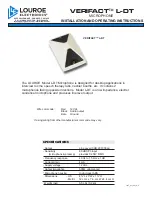
VERIFACT L-DT
Brand: Louroe Electronics Pages: 4

UHF-7
Brand: Nady Systems Pages: 6

UB-16
Brand: Nady Systems Pages: 6

UB-10
Brand: Nady Systems Pages: 7

UHF-116HL
Brand: Gemini Pages: 21

Endurant
Brand: Eaton Pages: 248

N767a
Brand: Electro-Voice Pages: 2

SKM 4031
Brand: Sennheiser Pages: 22

Security-Center ProfiLine TV8720
Brand: Abus Pages: 37

EK 100 G3
Brand: Sennheiser Pages: 3

SCT-800
Brand: T.BONE Pages: 2

GGM PAMICUHFG
Brand: GIGAMEDIA Pages: 13

SmartMike Classic
Brand: Sabinetek Pages: 32

FRQ-4
Brand: Hollywood Pages: 6

alpha
Brand: Audix Pages: 33


