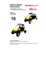
background image

Owner’s Manual


Parts manual 


READ THIS MANUAL CAREFULLY 
IT CONTAINS IMPORTANT SAFETY INFORMATION.


MINIMUM 
RECOMMENDED 
OPERATOR AGE:


FOR OFF-ROAD USE ONLY 

This vehicle is designed and manufactured for off-road use only. 

USA only; 

It does not confirm to federal motor vehicle safety standards, and operation on public streets, 

roads, or highways is illegal. 

16 

TROOPER-T2

T4

Summary of Contents for TROOPER-T2

Page 1: ...ETY INFORMATION MINIMUM RECOMMENDED OPERATOR AGE FOR OFF ROAD USE ONLY This vehicle is designed and manufactured for off road use only USA only It does not confirm to federal motor vehicle safety standards and operation on public streets roads or highways is illegal 16 TROOPER T2 T4 ...

Page 2: ...he features and operation of this vehicle It also includes basic maintenance and inspection procedures If you have any questions regarding the operation or maintenance of your vehicle please consult a JOYNER dealer Please read this manual carefully before operating this vehicle Do not attempt to operate this vehicle until you have attained adequate knowledge of its controls and operating features ...

Page 3: ...our vehicle ready to drive 26 Pre drive Inspection 26 Operation instructionMain switch 28 Battery switch 28 Gauges 29 Switches 29 Steering wheel 31 Pedal 32 Parking brake lever 32 Drive select lever 33 Differential control handle 33 Fuel tank 34 Seats and safety belts 34 Safari bed 36 Start engine 36 Stop engine 37 Passenger 37 Break in 37 Starting and operating instructions 38 Specifications 39 M...

Page 4: ...justment 62 Chassis wiring diagram 64 Engine wiring diagram 65 Engine disassembly installation and repair 66 Timing Belt 66 Camshaft 73 Cylinder head 82 Water pump 89 Oil pump 90 Crankshaft connecting rod mechanism 98 Electric injection system 109 PARTS MANUAL 149 1 ENGINE 149 1 COOLING SYSTEM 149 2 CYLINDER BLOCK 150 3 CRANKSHAFT 151 4 EXHAUST MANIFOLD 152 5 INTAKE SYSTEM 153 5 INTAKE SYSTEM 154 ...

Page 5: ...ism 184 5 Steering assembly 185 5 Steering assembly 186 5 Steering assembly 187 6 Throttle parking brake brake 188 6 Throttle parking brake brake 190 6 Brake TR1100 07 01 01 00B TR1100 07 01 01 00B T4 192 6 Parking 193 6 Clutch TR1100 07 04 01 00 TR1100 07 04 01 00 T4 194 7 Front and rear suspension assembly 195 7 Front and rear suspension assembly 196 8 Driven system 197 8 Driven system 199 9 Fro...

Page 6: ...6 16 Seats and safety belts 218 17 Other parts 220 17 Other parts 221 DEALER PRE DELIVERY INSPECTION 222 ...

Page 7: ...7 Owner s manual Warranty policy ...

Page 8: ...8 ...

Page 9: ...9 ...

Page 10: ...10 ...

Page 11: ...11 Parts order form warranty claim form ...

Page 12: ...12 Service record form ...

Page 13: ...13 Preventative maintenance and service log ...

Page 14: ...14 ...

Page 15: ...15 ...

Page 16: ...16 ...

Page 17: ...17 ...

Page 18: ...rstand all of the labels on your vehicle They contain important information for safe and proper operation of your vehicle Never remove any labels from your vehicle If a label becomes difficult to read or comes off a replacement label is available from your Joyner dealer ...

Page 19: ...19 ...

Page 20: ...20 ...

Page 21: ...21 ...

Page 22: ...n and maintenance procedures and schedules described in this manual 11 Always keep both hands arms feet and legs inside the vehicle at all times during operation Keep your feet on the floorboard Never hold onto the enclosure except when using the handgrip inside the enclosure Otherwise your hand could be injured if it is caught between the enclosure and an obstacle outside the vehicle 12 Always ke...

Page 23: ...than the floorboards on this model Remember that wet brakes may have reduced stopping ability Test your brakes after leaving water If necessary apply the brakes lightly while the vehicle is moving so the friction dries out the lining 23 Always be sure there are no obstacles or people behind you when you operate in reverse When it is safe to proceed in reverse go slowly Do not brake abruptly when c...

Page 24: ...t possible wearing proper gear can reduce the chance of injury when you drive The following suggestions will help you choose the proper driving gear Helmets and ayes protection Your helmet is your most important piece of driving gear because it offers the best protection against head injuries A helmet should fit your head comfortably and securely An open face helmet offers some protection but a fu...

Page 25: ...rn over Age recommendation It is strongly recommended that no one under the age of 16 permitted to ride the TROOPER without adult supervision A child driving a TROOPER that is not recommended for his her age could lose TROOPER control and result in severe injury or death A child under 16 should have adult supervision when operate on TROOPER No alcohol or drugs Alcohol drugs and TROOPER don t mix E...

Page 26: ...e Inspection Check the following items before you get on TROOPER Engine Oil Check the level and add oil if needed Check for leaks Coolant With the engine cold check the coolant and add if needed Check for leaks Fuel Check the level and add fuel if needed Also make sure the fuel cap is securely fastened Check for leaks Tires Use a gauge to check the air pressure Adjust if needed Also look for signs...

Page 27: ...thly without sticking and snaps back automatically when it is released Brakes Press the brake pedal several times check for proper brake pedal free play Make sure there is no brake fluid leakage Engine Stop When engine is running turn the switch key counterclockwise Make sure engine stops Steering Wheel Check that the wheels turn properly as you turn the steering wheel Cable Check the cable housin...

Page 28: ...Release the key when the engine starts Do not operate the electric starter continuously for more than 5 seconds or starter damage could occur Wait at least 5 seconds between each operation of the electric starter to let it cool Do not turn the key to the START position with the engine running or damage to the electric starter can result See starting instructions prior to starting the engine Batter...

Page 29: ...er which shows the engine rotate speed 3 a speedometer This shows the riding speed in Km MPH 4 a coolant thermometer which shows the coolant temperature 5 a voltmeter which shows the battery charge capacity 6 a oil pressure gauge which shows oil pressure Switches Light switch Set the switch to to turn on the low beam and the taillights Set the switch to to turn on the high beam and the taillights ...

Page 30: ... 4WD Power is delivered to both the front and the back wheels z Front free the vehicle working with front differential z Front lock the vehicle working with front differential locked z Rear free the vehicle working with rear differential z Rear lock the vehicle working with rear differential locked z To change from 2WD to 4WD bring the vehicle to a complete stop set the gear in neutral press the 4...

Page 31: ... if the temperature is above 1020 C 2150 F stop engine immediately Check coolant lever and add if low see authorized JOYNER dealer if temperature indicator stay on and overflow tank is full of coolant Oil pressure indicator light It indicates over low over high oil pressure when illuminated see authorized JOYNER dealer if necessary Steering wheel Steering wheel is used to control the direction it ...

Page 32: ...the rest position fully when released z If anyone of them can t work well please correct the problem before operating the engine If you can t find or solve the problem yourself please get the help from your JOYNER dealer z Improper operation of the clutch will lead to excessive wear of the clutch friction surface z When operating the vehicle if it does not feel comfortable about clutch or throttle...

Page 33: ...tial control handle Moving the differential control handle up and down to make the differential work and locked 2 handles control front differential and rear differential respectively Choose the work mode that you need according to the terrain situation The following work mode is available z 2DW 2 driven wheels 1 Rear differential 2 Rear differential locked z 4DW 4 driven wheels 1 Rear differentia...

Page 34: ...d the lever in that position and adjust the seat to the desired position Be sure the adjustment lever is back on its full lock position and the seat is locked in place 1 Pull seat lock lever under left leg upward 2 Move the Seats backwards or forwards as your need 3 Release the lock lever so the Seat is locked in the position you want To access the battery compartment the compartment is located un...

Page 35: ... across above right shoulder left shoulder right leg left leg and among two legs Make sure the belt is not twisted and is not caught on any portion of the vehicle your clothing or any equipment you are carrying see right picture Cross above right shoulder Cross above left shoulder Cross above right leg Cross above left leg Cross between 2 legs Cross above left leg Back Hook Limiting rock Take off ...

Page 36: ...pped Safari bed Safari bed can be lift up 1 Pull up the release lever on the both side of the vehicle 2 Lift up the safari bed slowly until it stops 3 Lower the safari bed slowly to its original position and make sure it is locked tightly z Before closing the bed be sure others are standing away from the vehicle Keep hands and fingers away from the pinch points between the bed and frame z The max ...

Page 37: ...the starter motor clutch or gearbox z Release the key at once if the engine starts Holding the key in start position when the engine is running will cause damage to the starter motor z If the engine does not start after 5 seconds a second attempt to start the engine can be allowed Improper operation will damage the engine Stop engine 1 It is strongly recommended to stop vehicle before stop engine ...

Page 38: ...d tighten the seat belts Testing TROOPER in a open place at the beginning to learn how to start turn and stop Operate TROOPER slowly until you are familiar with it The turning radius of TROOPER is small and agile so the centrifugal force is very high when turning at high speed Slow down to a more controllable speed when turning to prevent TROOPER from rolling over To prevent vehicle from rolling o...

Page 39: ...stem Lubrication system Liquid cooled 4stroke Upstanding double cylinder 1080cc 72mm 66 5mm 2 83 inch x2 62 inch 9 5 1 Electric starter Wet sumb Engine oil Type Recommended engine ail classification Quantity With oil filter cartridge replacement 0 SE15W 40 0 SE15W 30 3 0L 3 17qt Final gear case oil Type Quantity SAE85 API GL 5 gear oil 1 8L 1 9 qt Radiator capacity including all routes 5 0L 5 28 q...

Page 40: ...hock absorber Front shock absorber Rear shock absorber Coil spring oil damper Coil spring oil damper Wheel travel Front wheel travel Rear wheel travel 120mm 4 72inch 150mm 5 9inch Electrical Ignition system Generator system Battery type Battery capacity Distributor block AC magneto Lead acid storage battery 12V 45Ah Specified fuses High beam fuse Low beam fuse Turning light fuse Tail light fuse Br...

Page 41: ...41 Spotlight 12V 35W 35W 4 Indicator lights Reverse indicator light Coolant temperature warning light Charge indicator light Four wheel drive indicator light LED LED LED LED ...

Page 42: ...the air filter if dusty blow off dust with clear and dry air If necessary replace with a new one Engine Lubrication 1 Engine oil replacement You must change the oil in the crankcase refer to Preventative maintenance and service log That will insure proper lubrication of internal parts and prevent costly repairs due to excessive wear Oil inlet plug Cover Filter Rubber bushing Oil inlet Oil measurer...

Page 43: ...nd recharge If the color of engine oil changes you need to replace the engine oil as above Check the engine oil level charge if the oil level is lower than L Transmission lubrication Oil replacement You must change the oil in the transmission refer to Preventative maintenance and service log That will insure proper lubrication of internal parts and prevent costly repairs due to excessive wear a Pu...

Page 44: ...rential oil outlet plug Loosen the oil outlet plug in the differential Let the oil out fully c Remove the iron dust plug this plug has a magnet on it Iron dust caused by moving parts will stick to the plug Clean the iron dust from this dust plug d Tighten the differential oil outlet plug e Remove the oil inlet plug fill oil API 80 75 W 90 GL 3 Gear Oil about 0 4 liters f Replace the oil inlet plug...

Page 45: ...ume j Close the reserve coolant case cap turn it clockwise and tighten it z Opening the radiator cap while the engine is hot can be hazardous Opening the radiator cap can spray the high temperature coolant in your eyes face and any parts of your body This can result in severe injury Never open the radiator cap while the engine is hot z Children and pets may be harmed by coolant Keep coolant away f...

Page 46: ...RPM b Adjust the screw and adjust the idle speed to an ideal value c Repeat step b until the RPM of engine stables Spark plug inspection z Clean spark plug Check spark plug refer to Preventative maintenance and service log if too much carbon adhered which will weaken the spark Clear the carbon adhered with a dry brush and scratch the carbon adhered to insulating lay carefully with a file And blow ...

Page 47: ...cial spanner torque 25N m 18 4Ft Lb 6 Connect high voltage wire in order Engine damage or working unsteadily may occur if 1 Not install the spark plug correctly 2 Use a forbidden spark plug To avoid damage follow the following items 1 Tighten spark plug to a required torque 25N m over tightening will damage the screw 2 Removing or installing a spark plug make sure the slot aligned 3 Do not pull th...

Page 48: ...e than 10mm 0 4inch it is necessary to replace the belt When checking the wedge belt never start engine or body injury even death may occur Shift cable adjustment After a long time use more and more free play of shift cable make gear position is not accurately or shift lever in a wrong position so adjust the shift cable refer to Preventative maintenance and service log 1 Loosen the adjustment nuts...

Page 49: ...er decrease so adjust the shift cable refer to Preventative maintenance and service log 1 Loosen the adjustment nuts move the cable forwards or backwards according the situation repeat it until find a position where free play is gone 2 Tighten all of the adjustment nuts Adjustment nuts Adjustment nuts Shift lever Transmission ...

Page 50: ...the steering box off from TR1100 firstly unbolt these nuts and bolts showed in the following picture pull off the steering joint and take off the steering box slowly 2 Inject lithium base grease about 20g through grease cup with a grease gun 3 Clean the steering box and install it with reverse step 1 Adjustment nut Adjustment nut Parking brake lever Unbolt the nut Unbolt the bolt Unbolt the bolt P...

Page 51: ...gh following step 2 is necessary or not necessary 2 Unbolt the pedal end adjustment nuts shown in the following picture and move the cable end backwards to make the cable in a proper tension and then tighten 2 adjustment nuts Differential lock cable adjustment After a long time used the throttle cable may be too loose to work well so adjustment is needed It is recommended to adjust the differentia...

Page 52: ... nut and turn the spot light forwards and backwards until find the desired position Solution 2 2 Loosen the adjustment nuts on at the both ends of spot light lever and then rotate the lever clockwise to pull the spot light support up or counter clockwise to push the spot light support down Screw sleeve Thin nut Adjustment nut Spot light adjustment nut Adjustment nut Spot light ...

Page 53: ...3 5kgf m2 49 8 psi It s not necessary to adjust fuel pressure unless the fuel pressure really needs to be adjusted To adjust the fuel pressure 1 Loose the lock nut with a 14mm spanner as the following picture 2 Turn the adjustment bolt clockwise with a inner hexagon spanner to increase the fuel pressure and counterclockwise to decrease the fuel pressure 3 Keeping one eye on the fuel pressure indic...

Page 54: ...NER authorized dealer Castle nuts Torque 180 5 N M 182 3 5FT_LB Wheel nuts Torque 70 5 N M 51 3 5FT_LB Rear Wheel Replacement It is not needed to disassemble the center castle nuts when you replace the front wheels or the rear wheels Just take off these 5 cap nuts and replace the wheels with a new one Tighten these 5 nuts after replacing the wheels the wheel need to be assembled by a JOYNER author...

Page 55: ...arefully 2 Remove four bolts on the transmission case lay down these carefully Caution When fix the four bolts in the transmission case you must tighten them according to the prescribed torque 45 55 N M 33 40 5 Ft Lb Q1840845 Q1841245 S11 37081 Q218B1245 Q1841240 Q1841245 ...

Page 56: ...pine shaft into the hole of the Clutch assy remove the six bolts on the Clutch pressure plate now It s clear Caution When fix the six bolts in the Clutch pressure plate You must tighten them according to the prescribed torque 20 5 Ft_Lb S11 170010 372 100203 Spline shaft ...

Page 57: ...57 5 Insert a spline shaft into the hole of the Clutch assy fix the six bolts on the Clutch pressure plate and tighten them according to the prescribed torque 20 5 Ft_Lb S11 1601020 S11 1601030 FIGURE 1 ...

Page 58: ...teering wheel to align the center of the steering rack with the center of the frame d Loose the lock nuts on both ends of Front Tie Rods Turn the 2 tie rods forwards to increase A and decrease B backwards to decrease A and increase B repeat it until the dimension A and B meet the requirement described as item a and then tighten all the lock nuts on the both end of tie rod Fuse and relay To check o...

Page 59: ...t relay High beam light relay Dipped beam light relay Flash relay Night light fuse R gear indicator fuse Brake indicator fuse Turning single fuse Head light fuse Dipped beam fuse High beam fuse Horn fuse Spot light fuse Press the hook down ...

Page 60: ...e picture 3 Unscrew the screw that fixes the bulb and take off the bulb carefully 4 Disconnect the bulb from the wiring 5 Connect a new bulb with the same specification to the wiring 6 Put all the parts disassembled above with reversing step 1 4 Engine relay Fuel pump relay Fan relay ECU normal open circuits fuse Gauge and indicator fuse EFI fuse ECU normal close circuits fuse Fuel pump fuse Engin...

Page 61: ...61 Hoop Screw Screw driver Separate the head light carefully Unscrew the bulb screw Take off the bulb carefully Separate the head light like this ...

Page 62: ...eplace a new one 4 Put all the parts back with reversing step 1 2 Shock adjustment After a long time use the shock need to be adjusted for more tension refer to maintenance and service log adjust the shock with a special spanner In other case the chock nitrogen needs to be added to get more nitrogen pressure the recommended nitrogen pressure is 1 0MPa 145psi Adjust the shock refer to the following...

Page 63: ...3518 S mm P N 35 0 11299 155 2551 Rear shock spring specification 1 Loose the lock nut on the top of the shock spring and then turn the pushing nut clockwise to increase tension and counter clockwise to decrease tension Lock nut Pushing nut Special spanner Clock wise Special spanner ...

Page 64: ...ndicator Body wiring conn 28 water temperture Swich Reverserwarning Fuse 5A High beam switch Spot light switch 1 Dipping beam switch Spot light switch Brakes light R Brakes light L Fuse 5A Brakes light switch Fuse 5A Horn button Horn button Master switch Spot light signal IGN 1 Battery IGN 1 Start motor ST 4WD Convertor switch Convertor Capstan switch Capstan relay Reverse light R Reverse light L ...

Page 65: ...65 Engine wiring diagram ...

Page 66: ...allation and repair Timing Belt 1 Configuration diagram 1 Water pump pulley 2 Timing belt cover upper 3 Timing belt cover Lower 4 Torsion shock absorber 5 Timing pulley damper 6 Tensioner 7 Crankshaft timing pulley 8 Timing belt ...

Page 67: ...2 Removing timing belt cover Torque 6 1N m 18 5 0 7Ft_Lb 2 3 Remove tensional vibration damper 2 3 1 Fix the flywheel and prevent the gear ring from rotating 2 3 2 Remove bolt of tensional vibration damper 2 3 3 Ensure the mark on the timing belt match the mark on the oil pump 2 4 Remove timing belt covers ...

Page 68: ...assemble according to original state 2 5 3 Make sure that the crankshaft timing pulley wheel mark is aligned with the mark of the oil pump 2 5 4 Remove the tensioner bolt and take off the tensioner 2 6 Remove the timing belt Caution It is absolutely not allowed to use screw driver or some other sharp edged tools to remove the belt Attention Pay attention to the following points while using timing ...

Page 69: ...t necessary to refill the water continuously 2 8 5 2 There are much oil stains on the belt the belt should be replaced for the rubber will be damaged when it is expanded Specifications and model of the timing belt Part number P 372 1007081BV Belt wide 27 0 mm 1 06inch Timing belt tensioner Turn the belt tensioner supporting stand bolts to see if there is any abnormal sound Check to see if there ar...

Page 70: ...f the air exhaust camshaft so as to make the positioning groove on the gear be aligned with the positioning pin on the end surface of the camshaft Then use screws to fix the clockwise gear with the torque of 100 5N m 73 7 3 68Ft Lb 3 2 2 Make sure that the punched mark on the crankshaft clockwise pulley is aligned with the mark of the oil pump 3 3 Install the tensioner 3 3 1 Adjust the tension of ...

Page 71: ...tions the key is to adjust the above mentioned stretcher fastening bolt by widening he spacing Tighten the S A fixing bolt of the stretcher with the specified torque of 25 3N m 5 62 0 67FT Lb 3 4 Install the baffle of the crankshaft timing pulley Attention Install the baffle towards the direction shown in the right figure 3 5 Install the tensional vibration damper use SST 3 5 1 When there is not a...

Page 72: ...all timing belt cover Install seal strip in the position shown as right figure Install the position 1 and position 2 before cylinder head assembly install position 3 before tighten water pump Install the timing belt cover screw the bolt manually and then tighten them with a tool Torque 6 1N m 4 42 0 73Ft Lb 3 7 Install water pump pulley Torque 6 1N m 4 42 0 73Ft Lb ...

Page 73: ...r gasket 3 Camshaft timing pulley 4 Camshaft cover 5 Circular plug 6 Camshaft bearing cap 7 Exhaust camshaft 8 Intake camshaft 9 Oil seal 10 Spring retainer 11 Wave washer 12 Intake camshaft sub gear 13 Snap ring 14 Lock nut 15 Flange Non reusable part Unit N m kg cm Ft_Lb ...

Page 74: ... special tool Attention Manufacture a special tool according the right figure A special tool is needed to prevent the camshaft from rotate See figure below 2 3 Removal of camshaft bearing cover 2 3 1 Align the marks on the camshaft gears as shown in the right figure Timing mark Air outlet camshaft gear Air inlet camshaft gear ...

Page 75: ... camshaft slave gear 2 6 1 Use the special tool as shown in the right figure Clip the camshaft tightly and turn the gear to keep the bite state of master and slave gear remove the fixing bolts of slave gear Attention Do not damage the surface of the camshaft 2 6 2 Don t Use the special tool 1 Screw bolt M6 on the camshaft slave gear as the right figure show 2 Rotate the gear with a screwdriver rem...

Page 76: ...clearance is 0 1 0 170mm 0 0039 0 0067inch The air exhaust camshaft axial spacing is 0 1 0 173mm 0 0039 0 0068 inch Limits for operation 0 18mm 0 007 inch 2 7 3 Checks on camshaft meshing clearance 1 Put camshaft into cylinder head 2 Make sure the front mark on bearing cover and shaft number is ok and then tighten bolt 3 Fix air inlet camshaft and then measure the clearance with dial indicator Att...

Page 77: ...e surface of the camshaft 3 3 Installation of the camshaft Attention Size of the axial clearance of the camshaft 3 3 1 Smear lubricating oil at the camshaft gear section and the cylinder cover axial diameter section 3 3 2 Fix the camshaft slave gear by roughly adjusting on the cylinder cover 3 3 3 Install camshaft the timing mark must be aligned shown as the right figure 3 3 4 Smear lubricating oi...

Page 78: ...sing 1 1mm 0 0394 0 0394inch 3 7 Smear engine oil on the oil seal installation port of cylinder head camshaft oil seal edge of blade and outside ring use M10 bolt length 50 60 mm 1 9685 2 3622inch and SST press the cylinder lower 1mm 0 0394 inch than the end surface of the cylinder4 head Attention Under the condition of use the oil seal repeatedly press here with engine oil adhesive agent The oil ...

Page 79: ... tighten the bolts according the right figure Torque 6 1N m 6 0 7Ft_Lb 4 Routine check 4 1 Standard of valve clearance 4 2 Align the timing marks on the drive gear and driven gear 4 3 Use a plug gauge to measure the clearance according the right figure First cylinder Second cylinder Third cylinder Fourth cylinder I N EX I N EX I N EX I N E X O O O O valve clearance IN 0 18 0 05mm 0 007 0 002 EX 0 ...

Page 80: ...nce exceed the standard upwards and gap of valve lifter towards inside 4 4 2 Rotate camshaft and the cam press valve lifter down 4 4 3 Load the special tool at the top of the valve lifter around the valve lifter and then rotate camshaft to make the cam top upwards press valve lifter down with a special tool and hold it 4 4 3 1 Move the adjusting washer out with a screwdriver and then remove the wa...

Page 81: ...t the throttle clearance Attention Install the feeler with the identification mark facing downwards 4 4 3 5 Rotate camshaft to make cam top downwards and the throttle to be pressed down and then take special tool out 4 4 3 6 Rotate camshaft 2 3 round and then recheck the valve clearance if valve clearance can t get to the standard repeat 4 1 4 4 to adjust the valve clearance 2 18 0 0858 2 4 0 0944...

Page 82: ...diagram 1 Spark plug20 1Nm 2 Cylinder head 3 Weather seal I 4 Cylinder head gasket 5 Adjust shim 6 Valve lifter 7 Keeper 8 Valve spring seat 9 Valve spring 10 Intake valve 11 Exhaust valve 12 Valve oil seal 13 Valve seat 14 Valve guide ...

Page 83: ...ng block throttle spring stand valve spring IN valve and EX valve 2 6 Removal of valve oil seal and valve spring washer 2 7 Clearing 1 The accumulated carbon residue covered on the valve must be cleared 1 Use scraper to clear the cylinder cover the air inlet and exhaust branching pipe surfaces and bottoms Attention Do not damage the cylinder cover surface by scraping during the process of clearing...

Page 84: ...ameter of the throttle guiding pipe and use a caliper to measure the outer diameter 3 3 2 2 Work out the differences of the measured values If it is above the specified limits the throttle or the guiding pipe must be replaced Attention The measurement points are shown as the figure Work out the clearance of the final torn and worn section item standard limit wide IN 0 85 1 41 0 0335 0 0555 EX 1 07...

Page 85: ...ntion In the process of driving in the guiding pipe into the cylinder cover the operation should be carried out slowly until the pipe gets to the proper position No excessive driving should be exerted Pay attention to the specifications in the operation Driving in depth of throttle guiding pipe 3 3 3 4 Use reamer to grind the inner diameter to achieve the standard value of the clearing 3 3 4 Valve...

Page 86: ... outwards 3 3 4 6 Use polishing agent to grind and polish the throttle sealing 3 4 Assemble of cylinder head 3 4 1 Cylinder head Pay attention to the following instructions in the process of assembling for the other accessories on the cylinder cover 3 4 2 Spark plug insulator 1 Put the spark plug insulator in the corresponding hole on the cylinder head with special use auxiliary tools smear fluid ...

Page 87: ...of paintings on the valve spring valve spring of same engine should have the same identification paint marking 3 4 3 3 Install the locking blocks for the valve spring stands Warning Protective eye glasses must be worn in the process of this operation to protect the eyes Beware of the flying spring and other objects Upon completion of the installation of the throttle springs and throttle spring sta...

Page 88: ...n 2 3 operations till the torque meets the specifications The torque for the first tightening operation is 30 2N m 22 1 5Ft_Lb the torque for the second tightening operation is 50 3N m 36 2 2Ft_Lb And the torque for the third tightening operation is 70 3 5 Nm 51 2 5Ft_Lb 3 4 4 3 Installation of the spark plug Torque 20 1Nm 14 0 7Ft_Lb Attention The tools should be placed vertically so as not to ma...

Page 89: ... dismount the water pump principal body 2 3 Removal of the dustproof sealing stripe 3 Clearing 3 1 Clearing of the mating surface of the water pump 4 Routine checks 4 1 Check to see if there are any deformation or damages 4 2 Use a hand wrench to see if the turning is OK and if it is smoothly lubricated 5 Installation 5 1 Install the dustproof sealing stripes 5 2 Install the water pump principal b...

Page 90: ...dures 1 Oil pan tighten bolt 8 2 Nm 5 9 1 47Lb_Ft Oil strainer Oil collector gasket Oil pump Oil pump gasket Rear oil seal bracket 2 Dismounting 2 1 The engine being turned upside down on the dismounting frame take off the bolts Remove the oil pan from the cylinder body Attention Do not make the oil pan flange section to be deformed Non reusable part ...

Page 91: ... pump cushion 2 4 Dismounting of oil seal stand 3 Clearing 3 1 For the mating surfaces of the oil bottom case oil pump and oil seal stands for the mating surfaces of the rear oil seal stand and oil pump scraper and chipping chisel or some other tools may be used to clear the used ones Attention Do not drop the residues into the cylinder body ...

Page 92: ... valve spring8 Relief valve9 Crankshaft front oil sealing10 Oil pump body 4 2 Disintegration 4 2 1 Weather seal Attention The weather seal are not reusable 4 2 2 Remove the oil pump cover Attention The bolt is assembled with glue loosen it with screw driver according to the illustrations 4 2 3 Remove the driven and drive rotor of the oil pump Non reusable part Unit N m kg cm Ft lb ...

Page 93: ...elief valve 4 2 6 Removal of the front oil seal of the crankshaft Attention The removed oil seals are not reusable 4 3 Routine checks 4 3 1 Checks on lubricating oil pump spacing 4 3 1 1 Follow the mark on the interior and exterior gears of the oil pump to place it into the lubricating oil pump body on the cylinder body 4 3 1 2 Use a feeler to measure the clearance between the interior gear and th...

Page 94: ...hould be no visible tears wears and scrapes on the pressure relief valve 4 4 Installation 4 4 1 After smearing lubricating oil on the lips of the new T shaped oil seals use SST to make the assembly Attention Use new oil seal The exposed part of the outer edge of the oil seal after being pressed in should be less than 0 5mm 0 0197inch 4 4 2 Assembling of the oil pump pressure relief valve and split...

Page 95: ...ing oil pump should be on the visible side when being assembled into the pump body 4 4 4 The new weather seal should be put inside the oil pump cover groove 5 Disintegrating and assembling of oil seal 5 1 Configuration diagram Mark Non reusable part Unit N m kg cm Ft_Lb ...

Page 96: ... new oil seal lip section 5 4 2 Install the oil seal shown as the right figure 6 Assembling 6 1 Assembling of the oil sealing stands Smear oil sealing silica on the oil sealing stands shown as the right figure Grease Letai 5699 Attention The liquid sealing silica is to be smeared to the mating section of the oil seal stands and cylinder body surface with a width of 3 4mm 0 118 0 157inch Torque 25 ...

Page 97: ... with the cylinder body 6 4 2 Apply sealing silica before assembling Grease Letai 5699 Attention The liquid cushion with silica line diameter of Ф3 4mm Ф0 1181 0 1574inch without any broken section Make the assembly in 15 minutes after the application of silica 6 4 3 Tighten in the sequence shown in the right figure with the torque of 6 1N m 4 4 0 7Ft_Lb from the center to the two sides Front Rear...

Page 98: ...ce 1 Connecting rod cover 2 Connecting rod bearing bush 3 Piston and connecting rod assembly 4 Main bearing cover 5 Crankshaft 6 Crankshaft bush 7 Thrust washer 8 Cylinder block 9 No 1 compression ring 10 No 2 compression ring 11 Oil ring 12 Piston 13 Connecting rod 14 Piston pin Non reusable part Unit N m kg cm Ft_Lb ...

Page 99: ...ance 2 2 1 Remove the bush cover Attention Parts and components of various cylinders should be placed in good order 2 2 2 Clean the bush and axle diameter 2 2 3 Place clearance gauge on the connecting bearing diameter Tighten bush cover according to regulated torque torque 40 2N m 28 1 5Ft_Lb Attention Do not turn the crankshaft 2 2 4 Remove the bush cover measure the maximum width of the spacing ...

Page 100: ... scraping the cylinder hoe and crankshaft connecting rod axle diameter Then knock the piston connecting rod out with the handle of a hammer Attention Put the parts and components of various cylinders in good order 2 3 Use a caliper to measure the crankshaft axial clearance If the axial clearance is above the limits it is needed to replace the axial thrust washer or the crankshaft Benchmark 0 089 0...

Page 101: ...he crankshaft tighten the bolts of bearing bush cover with specified torque Torque 70 3 5N m 51 5 2 5Ft_Lb Attention Tighten the bolts of the crankshaft bearing cover in three times to the regulated value in the sequence as shown in the right figure Attention Don t turn the crankshaft after tightening because of the clearance gauge 2 4 4 Remove the bearing cover and measure the maximum width of th...

Page 102: ...e piston pin to take off the piston and the connecting rod by using SST 3 Clearing 3 1 Cylinder body Warning Wear eyeglasses during the clearing operation to protect your eyes 3 1 1 Use flat chisel to clear the cylinder body the cylinder cover the oil bottom casing the oil pump and the oil seal 3 2 Piston Warning Wear eye glassed in the process of cleaning to protect your eyes 3 2 1 Use the old ri...

Page 103: ...standard diameter Φ72 00 72 01mm Φ2 8346 2 835inch 4 2 Piston 4 2 1 Check the clearance between the piston pinholes Use a caliper to measure the positions of the piston shown in the following figure with the maximum value as the size of the piston pin diameter 4 2 2 Use the inner diameter centimeter to measure the positions of the piston hole diameter shown as the following figure take the minimum...

Page 104: ...ng ends 4 2 6 1 Put the piston ring i n the position which is 45 mm under the cylinder hole top surface in order to make the piston ring keep flattened you can press the piston ring with piston top surface then use a piston gauge to measure the open clearance Benchmark mm inch Limit mm inch Primary ring 0 03 0 06 0 0012 0 0023 0 12 0 0047 Secondary ring 0 03 0 06 0 0012 0 0023 0 11 0 0043 Benchmar...

Page 105: ...er body it is needed to confirm the clearance of the replaced cylinder once again Datum 0 018 0 030mm 0 0007 0 0012inch 4 3 Crankshaft 4 3 1 Check the coaxiality of the main shaft diameter 4 3 1 1 Use the centimeter to measure the coaxiality Replace the crankshaft if the measurement result exceeds t he limit Limit 0 03mm 0 0012inch Attention The bending value should be 1 2 of the fluctuation for o...

Page 106: ...re After smearing lubricating oil to the piston pin use pressurizing device to assemble the piston and the connecting rod Attention Pay attention to the assembling direction when pressing in the piston pin The small bit of connecting rod should be heated to 300 572 while pressing the piston pin in the piston Exert pressure in the process of pressing to assure the alignment of the pin 5 2 Install P...

Page 107: ...il sink The bush lower installed in bearing cover must match thruster groove 5 3 4 Smear lubricating oil on the friction side opposite to the contact of the bush lower parts Install the parts according to the forward induction mark on the crankshaft bearing cover 5 3 5 After applying the lubricating oil tighten the bolts in the sequence shown as the right figure for 2 3 cycles with the specified t...

Page 108: ...ake sure the frontward indication mark on the piston Should be frontward and assemble the piston connecting rod with SST Attention The cylinder number on the piston connecting rod should be identical to the cylinder number 5 4 5 Assemble the connecting rod bearing cover and bush according to the following instructions 5 4 5 1 Smear a little lubricating oil on the bolt and screw nut stand before th...

Page 109: ...109 Electric injection system ...

Page 110: ...110 ...

Page 111: ...111 ...

Page 112: ...112 ...

Page 113: ...113 ...

Page 114: ...114 ...

Page 115: ...115 ...

Page 116: ...116 ...

Page 117: ...117 ...

Page 118: ...118 ...

Page 119: ...119 ...

Page 120: ...120 ...

Page 121: ...121 ...

Page 122: ...122 ...

Page 123: ...123 ...

Page 124: ...124 ...

Page 125: ...125 ...

Page 126: ...126 ...

Page 127: ...127 ...

Page 128: ...128 ...

Page 129: ...129 ...

Page 130: ...130 ...

Page 131: ...131 ...

Page 132: ...132 ...

Page 133: ...133 ...

Page 134: ...134 ...

Page 135: ...135 ...

Page 136: ...136 ...

Page 137: ...137 ...

Page 138: ...138 ...

Page 139: ...139 ...

Page 140: ...140 ...

Page 141: ...141 ...

Page 142: ...142 ...

Page 143: ...143 ...

Page 144: ...144 ...

Page 145: ...145 ...

Page 146: ...146 ...

Page 147: ...147 ...

Page 148: ...148 ...

Page 149: ...41 372 1307041 WATER PUMP WASHER 1 9 02 DLJ 372 1307018 372 1307018 SEAL STRIP 2 1 10 02 DLJ Q1840825 Q1840825 BOLT 11 11 02 DLJ 372 1307019 372 1307019 SEAL STRIP 3 1 12 02 DLJ 372 1307012 372 1307012 SEAL STRIP 1 1 13 02 DLJ 50 O 50 O O RUBBER RING 1 14 02 DLJ 372 1306016 372 1306016 SEAT THERMOSTAT OUTER 1 15 02 DLJ 372 1306020 372 1306020 THERMOSTAT ASSY 1 16 02 DLJ 372 1306001 372 1306001 THE...

Page 150: ...840830 Q1840830 HEXAGON FLANGE BOLT 1 6 02 DLJ 372 1002060 372 1002060 KNOCK SENSOR 1 7 02 DLJ 372 1002036 372 1002036 POSITION PIN 2 8 02 DLJ S11 3810010 S11 3810010 OIL PRESSURE SWITCH 1 9 02 DLJ 11G10GB308 11G10GB308 BALL 2 10 02 DLJ 372 1002024 372 1002024 PLUG 7 11 02 DLJ 372 1002023 372 1002023 BOLT 10 12 02 DLJ 372 1002045 372 1002045 COVER OIL CONTROL 1 13 02 DLJ 372 1012021 372 1012021 TI...

Page 151: ...472 1005010 CRANKSHAFT ASSY 1 9 02 DLJ 372 1005016 372 1005016 STOPPER PLATE 2 10 02 DLJ S11 1601101 S11 1601101 COVER SET BOLT 6 12 02 DLJ 372 1005036 372 1005036 PIN DOWEL 1 13 02 DLJ 372 1005030 372 1005030 REAR OIL SEAL 1 14 02 DLJ 372 1005021 372 1005021 REAR OIL SEAL BRACKET 1 15 02 DLJ Q1840820 Q1840820 HEXAGON FLANGE BOLT 5 16 02 DLJ 372 1005050 372 1005050 FLYWHEEL ASSY 1 17 02 DLJ 372 10...

Page 152: ...3 Q1200825F3 STUD 6 4 02 DLJ Q33008 Q33008 HEXAGON NUT 6 5 02 TR1100 04 04 03 TR1100 04 04 03 00 CATALYST PACKAGE 1 6 03 01 70 1 M10 40 05 70 1 2000 M10x40 INNER HEXAGON BOLT 4 7 02 DLJ S11 1205110JA S11 1205110JA OXYGEN SENSOR 1 8 02 DLJ Q1200835F3 Q1200835F3 STUD 1 9 02 SV1100 04 04 04 SV1100 04 04 04 00 SEAL FOR CATALYST PACKAGE 1 10 03 02 6172 1 M10 R 05 6172 2000 M10 NUT 1 1 2 3 4 5 7 9 8 6 1...

Page 153: ...NSOR 1 7 02 DLJ Q1400416 Q1400416 HEXAGON HEAD BOLT 1 8 02 DLJ 472 1008011 472 1008011 UPPER INTAKE MANIFOLD 1 9 02 DLJ Q1420645 Q1420645 HEXAGON HEAD BOLT 2 10 02 DLJ S11 1121012JA S11 1121012JA OIL GUIDE 1 11 02 DLJ 480EF 1112010 480EF 1112010 INJECTOR 1 6L 4 12 02 DLJ Q1200835F3 Q1200835F3 STUD 3 13 02 DLJ Q1200828F3 Q1200828F3 STUD 2 14 02 DLJ 472 1008021 472 1008021 GASKET INTAKE MANIFOLD 1 1...

Page 154: ...GON FLANGE BOLT 5 24 02 DLJ 372 1014130 372 1014130 CRANKCASE VENTILATION PIPE 3 1 25 02 DLJ Q1840820 Q1840820 HEXAGON FLANGE BOLT 2 26 02 DLJ S11 1108210DA S11 1108210DA CABLE ACCL 1 27 02 DLJ 472 1008012 472 1008012 GASKET INTAKE MANIFOLD 1 28 02 TR1100 04 01 01 01 TR1100 04 01 01 01 UPPER INTAKE MANIFOLD 1 29 02 DLJ 372 1008017 372 1008017 TIE IN 1 30 02 DLJ 472 1014123 472 1014123 PIPE 3 1 31 ...

Page 155: ...OIL PUMP WASHER 1 6 02 DLJ 372 1011030 372 1011030 OIL PUMP ASSY 1 7 02 DLJ Q1840825 Q1840825 BOLT 1 8 02 DLJ Q1840855 Q1840855 BOLT M8X55 2 9 02 DLJ Q1420612 Q1420612 HEXAGON HEAD BOLT 17 10 02 DLJ 372 1010017 372 1010017 OIL STRAINER WASHER 1 11 02 DLJ Q1200616 Q1200616 STUD 2 12 02 DLJ Q33006 Q33006 HEXAGON NUT 2 13 02 DLJ 372 1010010 372 1010010 OIL STRAINER ASSY 1 14 02 DLJ Q1840610 Q1840610 ...

Page 156: ...J Q1400816 Q1400816 HEXAGON HEAD BOLT 1 8 02 DLJ 372 1003023 372 1003023 GUIDE VALVE 16 9 02 DLJ 372 1003022 372 1003022 EXHAUST VALVE SEAT INSERT 8 10 02 DLJ 372 1003021 372 1003021 INTAKE VALVE SEAT INSERT 8 11 02 DLJ 472 1003040AB 472 1003040AB GASKET CYLINDER HEAD 1 12 02 DLJ 372 1003202RA 372 1003202RA HANGER FRONT ENGINE 1 13 02 DLJ Q1840816 Q1840816 HEXAGON FLANGE BOLT 2 14 02 DLJ 372 10030...

Page 157: ...SENSOR SET 1 19 02 DLJ 372 1003201BA 372 1003201BA REAR HINGER 1 20 02 DLJ 372 1003026 372 1003026 PLUG 3 21 02 DLJ 372 1003024 372 1003024 PLUG 1 22 02 DLJ 372 1003028 372 1003028 PLUG 1 23 02 DLJ 372 1003038 372 1003038 STUD 1 24 02 DLJ 372 1003076 372 1003076 SLEEVE 1 25 02 DLJ 372 1003025 372 1003025 PLUG 1 1 19 2 3 4 5 6 7 20 25 22 24 10 8 9 11 12 13 14 15 16 21 23 17 20 ...

Page 158: ...OVER ASSY 1 2 02 DLJ Q2540616 Q2540616 SCREW 8 3 02 DLJ 472 1003075 472 1003075 COVER 1 4 02 DLJ 472 1003030 472 1003030 VALVE CHAMBER 1 5 02 DLJ 472 1003036 472 1003036 GASKET VALVE CHAMBER 1 6 02 DLJ Q1460625 Q1460625 HEXAGON HEAD BOLT 5 7 02 SV1100 04 01 05 01 SV1100 04 01 05 01 SPARK PLUG SEAL 4 1 3 2 6 5 7 ...

Page 159: ... Name Quantity 1 02 DLJ 472 1009010A 472 1009010A OIL PAN ASSY 1 2 02 DLJ Q1420612 Q1420612 HEXAGON HEAD BOLT 17 3 02 DLJ 372 1009017 372 1009017 SEAL WASHER OIL DRAIN THREADED PLUG 1 4 02 DLJ 372 1009014 372 1009014 MAGNET PLUG 1 1 2 3 4 ...

Page 160: ...G 1 8 02 DLJ 372 1006032 372 1006032 SADDLE FLIP WASHER 1 9 02 DLJ 372 1006031 372 1006031 DRIVE RING 1 10 02 DLJ 372 1006040 372 1006040 GEAR DERIVEN INTAKE CAMSHAFT 1 11 02 DLJ 372 1006030 372 1006030 GEAR MAIN INTAKE CAMSHAFT 1 12 02 DLJ 472 1006020 472 1006020 GEAR MAIN INTAKE CAMSHAFT 1 13 02 DLJ 372 1006071 372 1006071 HEXAGON FLANGE BOLT 1 14 02 DLJ 372 1006066 372 1006066 TIMING BELT SPROC...

Page 161: ...J 372 1007021 372 1007021 EDDY SLEEVE 16 24 02 DLJ 372 1007014BA 372 1007014BA VALVE SPRING UPPER SEAT 16 25 02 DLJ 372 1007013 372 1007013 SPRING VALVE 16 26 02 DLJ 372 1007020 372 1007020 VALVE SEAL 16 27 02 DLJ 372 1007016 372 1007016 LOWER VALVE SPRING SEAT 16 28 02 DLJ 372 1007012 372 1007012 EXHAUST VALVE 8 29 02 DLJ 372 1007081 372 1007081 TOOTHED TIMING BELT 1 30 02 DLJ 372 1007011 372 100...

Page 162: ...07014 372 1007014 VALVE SPRING UPPER SEAT 1 34 02 DLJ Q673B155 Q673B155 CLAMP 1 35 02 DLJ 472 1007042 472 1007042 LOWER COVER TIMING GEAR 1 36 02 DLJ 480 1011062 480 1011062 BOLT 1 1 2 3 4 5 6 35 36 29 34 33 28 27 26 25 24 21 23 22 20 32 19 18 17 16 15 14 13 12 7 8 9 10 11 31 30 ...

Page 163: ...NITION COIL 1 4 02 DLJ S11 3707100 S11 3707100 SPARK PLUG ASSY 4 5 02 DLJ Q1460820 Q1460820 HEXAGON HEAD BOLT 3 6 02 DLJ S11 3707020BA S11 3707020BA HI TENSION CORD NO 1 1 7 02 DLJ S11 3707030BA S11 3707030BA HI TENSION CORD NO 2 1 8 02 DLJ S11 3707040BA S11 3707040BA HI TENSION CORD NO 3 1 9 02 DLJ S11 3707050BA S11 3707050BA HI TENSION CORD NO 4 1 10 02 DLJ S11 3724183 S11 3724183 CLIP 1 1 2 3 4...

Page 164: ...RP code Part number Name Quantity 1 02 DLJ 372 1004031 372 1004031 PISTON PIN 4 2 02 DLJ 372 1004021AC 372 1004021AC PISTON 4 3 02 DLJ 372 1004110 372 1004110 CONNECTING ROD ASSY 4 4 02 DLJ 372 1004116 372 1004116 BEARING CONNECTING ROD 8 1 2 3 4 ...

Page 165: ...xhaust Gasket 1 8 03 02 6172 1 M12 R 05 6170 M12 1 75 Hex nut M12 1 75 1 9 03 04 93 φ12 05 93 SW12 Spring Washerφ12 1 10 03 03 95 φ12 24 2 5 05 97 1 W12 Washerφ12 1 11 03 01 70 1 M12 75 05 70 1 M12 1 75 75 25 Hex socket head bolt M12 1 75 75 25 1 12 02 DLJ Q218B1245 Q218B1245 Bolt 12 45 1 13 02 DLJ Q1841240 Q1841240 Bolt 12 50 2 14 02 DLJ 372 1002030 372 1002030 Upper steel cushion 1 15 02 DLJ S11...

Page 166: ...rt number Name Quantity 1 02 DLJ S11 3701110BB S11 3701110BB Alternator 1 2 02 DLJ S11 3701211BA S11 3701211BA Alternator bracket 1 3 02 DLJ S11 1001415BA S11 1001415BA Rear bracket 1 4 02 DLJ S11 3701315 S11 3701315 V ribbed belt 1 1 4 2 3 ...

Page 167: ...0 5T07 1701020 Side cover 1 4 02 DLJ 5T07 1702010 5T07 1702010 Declutch bearing 1 5 02 DLJ 5T0 1702020A 5T07 1702020A Declutch fork 1 6 02 DLJ 5T07 1702004 5T07 1702004 Clutch fork 2 sleeve 1 7 02 DLJ 5T07 1702030 5T07 1702030 Clutch fork seal 2 8 02 DLJ 5T07 1702001 5T07 1702001 Clutch fork 1 sleeve 1 9 02 DLJ QR51 1701103 QR512 1701103 Double screw rod 2 10 03 01 5787 M8 40 05 5787 M8x40 Flange ...

Page 168: ...701009 Bearing stop plate 1 17 02 DLJ 5T07 1701004 5T07 1701004 Oil stop plate 1 18 03 01 5787 M6 12 05 5787 AM6X12 Flange bolt M6x12 2 19 03 02 2842 M6 05 7246 W6 Flat washer 6 4 20 02 DLJ 5T07 1701400 5T07 1701400 Oil groove 1 21 02 TR1100 04 01 02 01 TR1100 04 01 02 01 Clutch rocker 1 22 03 01 5787 M8 35 05 5787 AM8X35 Flange bolt M8x35 1 23 03 02 2842 M8 05 6177 1 8 Flange nut M8 1 24 02 DLJ 5...

Page 169: ... QR512 1701461 QR512 1701461 Fourth gear 1 6 02 DLJ 5T07 1701610 5T07 1701610 Front bearing of output shaft 1 7 02 DLJ 5T07 1701240 5T07 1701240 Needle bearing of 1ST 2ND gear 2 8 02 DLJ QR512 1701439 QR512 1701439 Synchronizer out ring of 1ST 2ND gear 2 9 02 DLJ QR512 1701406 QR512 1701406 Synchronizer middle ring of 1ST 2ND gear 2 10 02 DLJ QR512 1701435 QR512 1701435 Synchronizer inner ring of ...

Page 170: ...432 QR512 1701432 Synchronizer gear block of 1ST 2ND gear 3 16 02 DLJ 5T07 1701205 5T07 1701205 Synchronizer retainer of 1ST 2ND gear 1 17 02 DLJ 5T07 1701202 5T07 1701202 Spacer of 3RD 4TH gear 1 18 02 DLJ 5T07 1701250 5T07 1701250 Rear bearing of output shaft 1 19 02 DLJ QR512 1701187 QR512 1701187 Adjusting washer of rear bearing depen d 20 02 DLJ 4T08A 1701402 4T08A 1701402 Countershaft sleeve...

Page 171: ...07 1701150 Needle bearing of 3RD 4TH gear 2 6 02 DLJ QR512 1701257 QR512 1701257 Synchronizer ring of 3TH 4TH 5TH gear 1 7 02 DLJ QR512 1701250 QR512 1701250 Synchronizer assy of 3TH 4TH 1 8 02 DLJ QR512 1701252 QR512 1701252 Synchronizer gear hub of 3TH 4TH gear 1 9 02 DLJ QR512 1701251 QR512 1701251 Synchronizer gear sleeve of 3TH 4TH gear 1 10 02 DLJ QR512 1701254 QR512 1701254 Synchronizer spr...

Page 172: ...701110 Back bearing of input shaft 1 16 02 DLJ QR512 1701285 QR512 1701285 Spacer of 5TH gear 1 17 02 DLJ QR512 1701200 QR512 1701200 Input shaft assy 1 18 02 DLJ QR512 1701287 QR512 1701287 Adjusting washer of rear bearing Dem and 19 02 DLJ QR512 1701280 QR512 1701280 5TH gear assy 1 20 QR512 1701257 QR512 1701257 Synchronizer ring of 3TH 4TH 5TH gear 1 21 02 DLJ QR512 1701258 QR512 1701258 Synch...

Page 173: ...701291 QR512 1701291 Synchronizer gear sleeve of 5TH gear 1 27 02 DLJ QR512 1701294 QR512 1701294 Synchronizer ring of 5TH gear 1 28 02 DLJ QR512 1701298 QR512 1701298 Nut of 5TH gear synchronizer 1 29 02 DLJ QR512 1701710 QR512 1701710 Reverse gear 1 30 02 DLJ 5T07 1701053 5T07 1701053 Ring of reverse gear 1 31 02 DLJ 5T07 1701061A 5T07 1701061A Shaft of reverse gear 1 32 02 DLJ 5T07 1701052 5T07...

Page 174: ...all 7 9375 6 4 02 DLJ 5T07 1702042A 5T07 1702042A Shift fork of 5TH gear 1 5 02 DLJ 5T07 1702061A 5T07 1702061A Shift fork of 3RD 4TH gear 1 6 02 DLJ 4T08A 1702042A 4T08A 1702042A Stop block 1 7 02 DLJ QR512 1702231 QR512 1702231 PIN 4 5x20 1 8 02 DLJ QR512 1702411 QR512 1702411 Shift fork shaft of 1ST 2ND gear 1 9 02 DLJ 5T07 1702067 5T07 1702067 Shift fork shaft spring 3 10 02 DLJ QR512 1701421 ...

Page 175: ...ear 1 13 02 DLJ 5T07 1702234 5T07 1702234 Shift fork shaft screw plug 3 14 02 DLJ 5T07 1702233 5T07 1702233 Washer of screw plug 3 15 02 DLJ QR512 1702341 QR512 1702341 Shift fork pin of reverse gear 1 16 02 DLJ 5T07 1702068 5T07 1702068 Shift block spring 1 17 02 DLJ 5T07 1702050A 5T07 1702050A Shift arm 1 18 03 03 95 φ8 16 1 5 05 93 W8 Flat washer 8 2 19 02 DLJ 5T07 1702232A 5T07 1702232A Bolt o...

Page 176: ...assy 1 2 02 DLJ 5T07 1702101A 5T07 1702101A Shift selecting shift 1 3 02 DLJ QR512 1702214 QR512 1702214 Snap ring of shift interlock 3 4 02 DLJ 5T07 1702102 5T07 1702102 Release sprig seat of 1ST 2ND gear 1 5 02 DLJ 5T07 1702103 5T07 1702103 Release sprig of 1ST 2ND gear 1 6 02 DLJ 5T07 1702104 5T07 1702104 Spring stop plate 2 ...

Page 177: ...IL SEAL 1 23 02 DLJ 5T07 1702062 5T07 1702062 Anti dust cover of shift select shaft 1 24 02 DLJ 5T07 1702073 5T07 1702073 Limiting bolt of reverse gear 1 25 02 DLJ QR512 1702229 QR512 1702229 Washer of limiting bolt 1 26 03 07 882 6 12 05 119 P6x12 Pin B 6x12 2 27 03 01 5787 M8 20 05 5787 M8x20 BOLT AM 8x20 4 28 02 DLJ 5T07 1702065A 5T07 1702065A Limiting bolt of shift 1 29 02 DLJ QR512 1702229 QR...

Page 178: ... 02 DLJ 4T08A 1701603 4T08A 1701603 Connecting disc 1 7 02 DLJ QR512 1701611 QR512 1701611 Driven gear of speed reducer 1 8 02 DLJ 4T08A 1701605 4T08A 1701605 Rear bearing of output shaft 1 9 02 DLJ 5T07 1701320 5T07 1701320 Rearing bearing of differential 1 10 02 DLJ 5T07 1701309 5T07 1701309 Flange bolt 8 11 02 DLJ MQC4 2303016 MQC4 2303016 Retaining ring 2 12 02 DLJ 5T07 1701090 5T07 1701090 Ri...

Page 179: ...ead screw M6 16 48 5 02 JD 0900008 JD0900008 W6 Washer 6 53 6 03 02 6187 1 M6 05 6187 1 M6 Self locking nut M6 53 7 03 01 D818 M6 20 818 M6 20 Cross head screw M6 20 5 8 02 TR1100 01 01 03 03 TR1100 01 01 03 03 Lower steering room board FR 1 9 02 TR1100 01 01 03 01 TR1100 01 01 03 01 Front differential lower board 1 10 02 TR1100 01 01 03 02 TR1100 01 01 03 02 Lower steering room board FL 1 11 02 T...

Page 180: ... M6 16 818 M6 16 Cross head screw M6 16 74 5 02 JD 0900008 JD0900008 W6 Washer 6 79 6 03 02 6187 1 M6 05 6187 1 M6 Self locking nut M6 79 7 03 01 D818 M6 20 818 M6 20 Cross head screw M6 20 5 8 02 TR1100 01 01 03 03 TR1100 01 01 03 03 Lower steering room board FR 1 9 02 TR1100 01 01 03 01 TR1100 01 01 03 01 Front differential lower board 1 10 02 TR1100 01 01 03 02 TR1100 01 01 03 02 Lower steering...

Page 181: ...5 1 9 02 TR1100 01 02 12 TR1100 01 02 12 00 Engine mount left 1 10 03 01 5787 M8 25 05 5787 M8X25 Bolt washer M8X25 1 11 03 04 93 φ8 05 93 SS8 Spring shim 8 1 12 03 03 95 φ8 24 2 05 95 W8 Washer 8 1 13 02 TR1100 04 01 0100 TR1100 04 01 01 00 Engine 1 14 03 01 5787 M10 1 25 30 05 5787 M10X1 25X30 Bolt washer M10X1 25X30 2 15 02 TR1100 01 02 14 TR1100 01 02 14 00 Engine mount front 1 16 03 01 5787 M...

Page 182: ... bolt M10 40 1 5 2 5 02 TR1100 04 04 04 TR1100 04 04 04 00 Exhaust manifold 1 6 02 SV1100 04 04 04 SV1100 04 04 04 00 Seal washer 1 7 03 03 95 φ10 20 1 5 05 95 W10 Washer 10 2 8 03 04 93 φ10 05 93 SS10 Spring shim 10 2 9 03 02 6172 1 M10 R 05 5782 M10 40 1 5 Nut washer M10 40 1 5 2 10 02 TR1100 04 04 03 TR1100 04 04 03 00 Catalyst package 1 11 02 DLJ S11 1205110JA S11 1205110JA Oxygen sensor 2 12 ...

Page 183: ...0 05 02 01B TR1100 05 02 01 00B T4 Choosing gear cable 1 7 02 TR1100 05 02 02B TR1100 05 02 02 00B Changing gear cable 1 02 TRB1100 05 02 02B TR1100 05 02 02 00B T4 Changing gear cable 1 10 02 S800 05 02 06 S800 05 02 06 00 R2 Gear cable mount 1 11 03 01 5787 M8 75 05 5787 M8 75 Flange bolt M8 75 2 12 03 01 5787 M8 20 05 5787 M8 20 Flange bolt M8 20 1 13 02 S800 05 02 04 S800 05 02 04 00 R1 Gear c...

Page 184: ...aring 1 19 02 S800 04 01 02 S800 04 01 02 00 R2 5T07D1 Transmission 1 20 02 DLJ 5T07 1702063 5T07 1702063 Nylon 1 21 02 S800 05 02 04 S800 05 02 04 00 R2 Gear changing arm 1 22 02 DLJ 5T07 1702045 5T07 1702045 Small washer 1 23 02 DLJ 5T07 1702046 5T07 1702046 Big washer 1 24 03 04 93 φ8 05 93 SW8 Spring washer 8 1 25 03 02 6183 1 M8 05 6170 M8 Nut M8 2 26 02 DLJ 5T07 1702064 5T07 1702064 Rubber 1...

Page 185: ...heel assy 1 8 03 02 6187 1 M6 05 6187 1 M6 Self locking nut M6 6 9 02 S650 05 01 01 01 S650 05 01 01 01 Steering wheel shaft 1 10 02 S650 05 01 01 03 S650 05 01 01 03 Rubber cover 1 11 02 S650 05 01 01 02 S650 05 01 01 02 Steering column housing 1 12 03 09 894 1 φ15 894 1 CΦ15 External circlip Φ15 1 13 02 TR1100 05 01 01 TR1100 05 01 01 00 Steering column assy 1 14 03 01 5782 M8 25 05 5782 M8 25 H...

Page 186: ...SR2000 05 01 03 02 SR2000 05 01 03 02 Capping plate 1 24 02 SR2000 05 01 03 04 SR2000 05 01 03 04 Hook 2 25 02 TR1100 05 01 0001 TR1100 05 01 00 01 Location bush 2 26 02 SR2000 05 01 03 07 SR2000 05 01 03 07 Location nut M16X1 5 2 27 02 SR2000 05 01 03 03 SR2000 05 01 03 03 Gear rack 1 28 02 SR2000 05 01 03 01 SR2000 05 01 03 01 Socket 1 29 02 D800 05 01 03 08 D800 05 01 03 08 M8X1 nozzle tip 1 30...

Page 187: ...R1100 05 01 03 00 Steering cross rod 1 39 03 02 6172 1 M14 1 5 R 05 6173 M14 1 5 R Jam nut M14 1 5 R 2 40 02 S650 05 01 03 01 S650 05 01 03 01 Joint ball 2 41 03 03 95 φ14 28 2 05 95 W14 Washer 14 2 42 03 04 93 φ14 05 93 SS14 Spring shim 14 2 43 03 02 9457 M14 1 5 05 9457 M14 1 5 Slotted nut M14 1 5 2 44 03 08 91 φ3 2 30 05 91 CP3 2 30 Cotter pin 3 2 30 2 45 03 02 2842 M12 1 5 05 6177 1 M12 1 5 Nu...

Page 188: ...ke brake 16 6 15 11 18 8 9 10 21 3 20 25 2 3 4 6 7 5 12 1 13 14 17 19 20 22 26 27 28 1 1 1 1 24 1 1 29 3 3 3 30 3 31 29 31 29 21 21 21 21 32 17 33 34 35 36 17 37 38 39 39 39 41 42 40 3 43 44 33 1 41 42 3 45 46 47 48 29 49 50 51 ...

Page 189: ... 30 3 18 02 TR1100 07 02 01A TR1100 07 02 01 00A Parking brake assembly 1 19 03 01 5787 M6 35 05 5787 M6 35 Flange bolt M6 35 3 20 03 02 6187 1 M6 05 6187 1 M6 Flange nut M6 3 21 03 01 5787 M8 35 03 5787 M8 35 Flange bolt M8 35 11 22 02 TR1100 07 01 01B TR1100 07 01 01 00B Hydraulic braking assembly 1 02 TR1100 07 01 01B TR1100 07 01 01 00B T4 Hydraulic braking assembly 1 24 03 01 5787 M8 60 05 57...

Page 190: ...ke brake 16 6 15 11 18 8 9 10 21 3 20 25 2 3 4 6 7 5 12 1 13 14 17 19 20 22 26 27 28 1 1 1 1 24 1 1 29 3 3 3 30 3 31 29 31 29 21 21 21 21 32 17 33 34 35 36 17 37 38 39 39 39 41 42 40 3 43 44 33 1 41 42 3 45 46 47 48 29 49 50 51 ...

Page 191: ...03A Park pedal pin 1 44 03 08 91 φ2 5 30 05 91 CPφ2 5 30 Cotter pin φ2 5 30 1 45 02 TR1100 07 04 0001A TR1100 07 04 00 01A Clutch pedal pin 1 46 02 TR1100 07 04 02A TR1100 07 04 02 00A Clutch pedal 1 47 02 TR1100 06 04 03 TR1100 06 04 03 00 Braking switch 1 48 03 02 2842 M10 05 6177 1 M10 1 5 Nut washer M10 1 5 1 49 02 TR1100 07 01 0002 TR1100 07 01 00 02 Braking switch fixation 1 50 02 TR1100 07 ...

Page 192: ...00R ZJ509 05 00R Right caliper assy 2 7 02 TR1100 07 01 01 03 B TR1100 07 01 01 03B Right inlet hose of rear caliper 1 02 TRB1100 07 01 01 0 3B TR1100 07 01 01 03B T4 Right inlet hose of rear caliper 1 8 02 TR1100 07 01 01 04 B TR1100 07 01 01 04B Left inlet hose of rear caliper 1 02 TRB1100 07 01 01 0 4B TR1100 07 01 01 04B T4 Left inlet hose of rear caliper 1 9 02 DLJ ZJ709 04 00 16 ZJ709 04 00 ...

Page 193: ... 02 DLJ ZJ509 05 00R ZJ509 05 00R Right caliper assy 1 5 02 DLJ ZJ609 F02 01 ZJ609 F02 01 T connection 1 6 02 TR1100 07 02 01 03A TR1100 07 02 01 03A Left outlet hose of T connection 1 7 02 DLJ ZJ509 05 00L ZJ509 05 00L Left caliper assy 1 8 02 DLJ ZJ509 03 04 ZJ509 03 04 Hydraulic brake pad 2 9 02 DLJ ZJGS 01 02 ZJGS 01 02 Hose bolt M10x1 25 6 10 02 DLJ ZJGS 01 01 ZJGS 01 01 Seal washer 12 11 02 ...

Page 194: ...7 04 01 01 Outlet hose of Master cylinder 1 02 TRB1100 07 04 01 01 TR1100 07 04 01 01 T 4 Outlet hose of Master cylinder 1 3 02 DLJ ZJ709 04 00 1 6 ZJ709 04 00 16 Master cylinder 1 4 02 DLJ ZJ610 05 05 ZJ610 05 05 Ripple boot 1 5 02 DLJ ZJGS 01 02 ZJGS 01 02 Hose bolt M10x1 25 2 6 02 DLJ ZJGS 01 01 ZJGS 01 01 Seal washer 4 7 02 TR1100 07 04 01 TR1100 07 04 01 00 Clutch hydraulic pump assembly 1 ...

Page 195: ...washer M16 2 2 6 03 01 5787 M16 65 05 5787 M16 2 65 25 Bolt washer M16 2 65 25 8 7 02 D800 02 01 0004 D800 02 01 00 04 Spacer φ16 16 8 03 09 894 2 φ34 894 2 CΦ34 External circlip Φ34 4 9 02 TR1100 02 01 03A TR1100 02 01 03 00A Upper suspension arm FL 1 10 02 S650 02 01 01 S650 02 01 01 00 Ball joint 4 11 02 TR1100 03 01 0001A TR1100 03 01 00 01A Stub axle left 1 12 02 TR1100 02 01 04A TR1100 02 01...

Page 196: ...00 bearing 8 19 02 D800 02 02 0004 D800 02 02 00 04 Spacer 4 20 02 D650 02 01 0002 D650 02 01 00 02 Nut M16 2 4 21 02 TR1100 02 02 04B TR1100 02 02 04 00B Suspension arm RR 1 22 03 02 6185 1 M15 05 6185 1 M15 1 5 Nut M15 1 5 4 23 02 TR1100 02 02 01 TR1100 02 02 01 00 Rear shock 2 24 03 01 5782 M15 65 05 5782 M15 1 5 65 25 Hex bolt M15 1 5 65 25 4 25 02 TR1100 02 02 02B TR1100 02 02 02 00B Suspensi...

Page 197: ...23 24 25 5 6 7 8 9 10 11 12 11 13 9 14 15 16 3 4 17 18 19 20 4 3 1 21 26 27 28 29 28 37 38 39 40 6 5 30 31 32 33 41 39 38 40 6 5 5 6 40 44 43 47 42 44 43 46 31323334 35 36 40 6 5 25 26 20 48 49 50 49 48 51 3 52 17 54 20 18 52 20 48 49 50 49 48 51 3 5 6 7 8 9 10 11 12 11 13 9 14 15 53 45 45 ...

Page 198: ...g circlip 4 19 02 TR1100 03 01 04 TR1100 03 01 04 00 Front differential 1 20 03 02 2842 M12 1 6177 1 M12 1 25 Flange nut M12 1 25 8 21 02 TR1100 03 01 0002A TR1100 03 01 00 02A Stub axle right 1 22 02 S650 06 10 S650 06 10 00 00 Electric locker for 2WD to 1 23 03 03 95 φ6 12 1 05 93 FW6 Flat washer 6 2 24 03 01 D818 M6 16 818 M6 16 Cross head screw M6 16 2 25 03 08 91 φ3 2 30 05 91 CPΦ3 2 30 Cotte...

Page 199: ...23 24 25 5 6 7 8 9 10 11 12 11 13 9 14 15 16 3 4 17 18 19 20 4 3 1 21 26 27 28 29 28 37 38 39 40 6 5 30 31 32 33 41 39 38 40 6 5 5 6 40 44 43 47 42 44 43 46 31323334 35 36 40 6 5 25 26 20 48 49 50 49 48 51 3 52 17 54 20 18 52 20 48 49 50 49 48 51 3 5 6 7 8 9 10 11 12 11 13 9 14 15 53 45 45 ...

Page 200: ... R2 Rear tyre 27 11 14 2 44 02 S800 03 02 03 01 S800 03 02 03 01 R2 Rear rim 14 8 2 45 02 S650 03 02 0004 S650 03 02 00 04 Rear hub 2 46 02 TR1100 03 03 02A TR1100 03 03 02 00A Rear inboard slip driveshaft 1 47 02 S800 03 02 03 S800 03 02 03 00 R2 Rear left wheel 27 11 14 1 48 02 S650 02 01 0003 S650 02 01 00 03 Seal 8 49 02 S650 03 02 0001 S650 03 02 00 01 Bush 4 50 02 S650 03 02 0002 S650 03 02 ...

Page 201: ...0 05 5787 M8 20 Flange bolt M8 20 4 5 02 JD 1082101 JD1082101 Rubber cover 2 6 02 DLJ REV 33 TR1100 03 01 06 00A Release lever 2 7 02 DLJ REV 35 REV 35 Spring 2 8 02 DLJ REV 36 REV 36 Spacer 2 9 03 01 70 1 M8 60 05 70 1 M8 60 Hex bolt M8 60 2 10 02 DLJ REV 33 REV 33 Spring 2 11 02 TR1100 03 02 05B TR1100 03 02 05 00B Rear diff cable 1 02 TRB1100 03 02 05B TR1100 03 02 05 00A T4 Rear cable 1 12 03 ...

Page 202: ...ank and gasoline pump 55 54 53 27 Twenty two Washers 17 18 19 20 22 21 23 24 25 26 25 1 2 3 4 5 7 8 9 10 11 13 12 14 15 6 16 6 28 31 32 8 33 29 34 34 35 39 40 45 44 42 43 51 52 30 36 37 37 6 38 41 36 46 47 48 49 50 ...

Page 203: ...02 D800 04 05 01 D800 04 05 01 00 Air cleaner 1 18 02 SV800 04 05 000 SV800 04 05 00 02 Air cleaner rubber 1 19 02 N650 04 05 0001 N650 04 05 00 01 Hose clip 65 82 1 20 02 TR1100 04 05 01 TR11000 04 05 01 00 Air cleaner 1 21 03 01 5787 M8 5787 M8 35 Bolt washer M8 35 2 22 03 01 5787 M8 5787 M8 30 Bolt washer M8 30 3 23 02 DLJ 472 1008011 472 1008011 Up air inlet manifold 1 24 02 DLJ FT 0409 550 FT...

Page 204: ...ank and gasoline pump 55 54 53 27 Twenty two Washers 17 18 19 20 22 21 23 24 25 26 25 1 2 3 4 5 7 8 9 10 11 13 12 14 15 6 16 6 28 31 32 8 33 29 34 34 35 39 40 45 44 42 43 51 52 30 36 37 37 6 38 41 36 46 47 48 49 50 ...

Page 205: ...Cross head screw M5 35 1 44 03 04 93 φ6 05 93 SS6 Spring shim 6 2 45 03 02 41 M5 05 41 M5 Hex nut M5 1 46 03 01 70 1 M6 60 03 70 1 M6 60 Inner hex bolt M6 60 1 47 03 02 41 M6 05 41 M6 Hex nut M6 1 48 03 01 5782 M4 10 05 5782 M4 10 Hex bolt M4 10 2 49 03 03 95 φ4 05 93 SS4 Spring shim 4 2 50 03 03 93 φ4 05 95 FW4 Flat washer 4 2 51 02 SR2000 04 03 0004 SR2000 04 03 00 04 44 7x57 O seal 1 52 02 SR20...

Page 206: ... 02 SV800 04 07 0001 SV800 04 07 00 01 Hose clip 21 38 1 5 02 D800 04 07 0001 D800 04 07 00 01 Oil separator tank 1 6 03 01 5787 M8 20 05 5787 M8X20 Bolt washer M8X20 8 8 02 D1600 04 02 0006 D1600 04 02 00 06 Hose clip 16 25 6 9 03 01 5787 M10 1 25 5787 M10X1 25X2 Bolt washer 2 10 03 02 2842 M10 1 25 05 6187 M10 1 25 Self locking nut 2 11 03 02 6187 1 M8 05 6187 1 M8 Self locking nut M8 8 12 03 03...

Page 207: ...2 02 SV1100 04 02 02 SV1100 04 02 02 00 Small tee branch 1 23 02 TR1100 04 02 0003 TR1100 04 02 00 03 φ24 φ32 short engine water 1 24 02 TR1100 04 02 0005 TR1100 04 02 00 05 φ6 φ11aeration pipe 1 25 02 TR1100 04 02 01 TR1100 04 02 01 00 Aluminium radiator assy 1 26 03 03 95 φ6 12 95 W6 Washer 6 4 27 03 01 5787 M6 20 05 5787 M6 20 Bolt washer M6 20 4 28 02 D1600 04 02 02 D1600 04 02 02 00 Radiator ...

Page 208: ...2 1 5 30 2 5 03 01 5787 M10 1 25 25 05 5787 M10 1 25 25 Bolt washer M10 1 25 25 2 6 03 02 2842 M10 1 25 05 6177 1 M10 1 25 Nut washer M10 1 25 2 7 02 S800 09 01 04 S800 09 01 04 00 R2 Rearview mirror 2 8 03 01 5787 M5 12 05 5787 M5 12 Flange bolt M5 12 8 9 03 04 93 φ8 05 93 SW8 Spring washer 8 2 10 03 02 6183 1 M8 05 923 M8 M8 2 11 03 03 95 φ8 24 2 05 95 FW8 Flat washer 8 2 12 02 S800 09 01 06 S80...

Page 209: ...2 00B Left upper roll bar 2 19 02 TR1100 01 02 03A TR1100 01 02 03 00A Rear roll bar 1 20 02 TR1100 01 02 02C TR1100 01 02 02 00C Right upper roll bar 4 21 03 02 6183 1 M8 05 923 M8 Nut M8 6 22 03 01 5787 M8 25 05 5787 M8 25 Bolt washer M8 25 4 23 02 S800 10 01 03 S800 10 01 03 00 R2 Rod end bearing POSA8 1 25 2 24 03 02 6172 1 M8 R 05 6171 1 M8 Thin nut M8 2 25 02 TRB1100 01 02 25 TR1100 01 02 25...

Page 210: ...nner hex bolt M12 1 5 30 2 5 03 01 5787 M10 1 25 25 05 S800 09 01 04 00 R2 Rearview mirror 2 6 03 02 2842 M10 1 25 05 5787 M5 12 Flange bolt M5 12 8 7 02 S800 09 01 04 93 SW8 Spring washer 8 2 8 03 01 5787 M5 12 05 923 M8 Nut M8 6 9 03 04 93 φ8 05 95 FW8 Flat washer 8 2 10 03 02 6183 1 M8 05 S800 09 01 06 00 R2 Right bracket 1 11 03 03 95 φ8 24 2 05 70 1 M10 1 25 25 Inner hex bolt M10 1 25 25 24 1...

Page 211: ...3 TR1100 01 02 03 00 T4 Rear roll bar 1 19 02 S800 09 01 05 S800 09 01 05 00 R2 Left bracket 1 20 03 01 5787 M8 25 05 5787 M8 25 Bolt washer M8 25 4 21 03 02 6183 1 M8 05 S800 10 01 03 00 R2 Rod end bearing POSA8 1 25 2 22 03 02 6172 1 M8 R 05 6171 1 M8 Thin nut M8 2 23 02 TRB1100 01 02 25 TR1100 01 02 25 00 T4 Adjusting roll bar 2 24 03 02 6172 1 M8 L 05 6171 M8 L Thin nut M8 L 2 25 02 TRB1100 01...

Page 212: ... 07 00 Release lever 2 6 03 01 5787 M6 16 05 5786 M6 16 Bolt washer M6 16 8 7 02 TR1100 01 02 07 05 TR1100 01 02 07 05 Air shock 2 8 03 03 95 φ8 24 2 05 95 W8 Washer 8 2 9 03 07 882 12 130 05 882 PP12 130 B pivot pin 12 130 2 10 03 08 91 φ2 5 25 05 91 CPΦ2 5 25 Cotter pin Φ2 5 25 6 11 02 TR1100 01 02 07 06 3 TR1100 01 02 07 06 3 440 glue strip 2 12 02 TR1100 01 02 07 06 2 TR1100 01 02 07 06 2 520 ...

Page 213: ...650 06 12 0003 S650 06 12 00 03 Wire cable guide 1 5 03 01 5787 M8 25 05 5787 M8 25 Bolt washer M8 25 4 6 02 S650 06 12 0001 S650 06 12 00 01 Electrical winch 1 7 03 03 95 φ10 20 2 05 95 W10 Washer 10 2 8 03 08 91 φ3 2 30 05 91 CP3 2 30 Cotter pin 3 2 30 2 9 03 07 882 10 70 05 882 PP10 70 B pivot pin 10 70 2 10 02 S650 01 05 S650 01 05 00 00 Electrical winch mount 1 11 02 S650 06 12 0008 S650 06 1...

Page 214: ... locking nut M6 120 4 03 01 D818 M6 25 818 M6 25 Cross head screw 6 5 03 02 17880 1 M6 20 04 6187 1 M6 16 Nut M6 16 colour 4 6 03 01 D818 M6 20 818 M6 20 Cross head screw 54 7 02 TR1100 08 000004C TR1100 08 00 00 04C Instrument desk 1 8 02 TR1100 08 000016 TR1100 08 00 00 16 Front decorative 1 9 02 TR1100 08 000007 TR1100 08 00 00 07 Right front fender 1 10 02 TR1100 08 000006 TR1100 08 00 00 06 L...

Page 215: ...100 08 000002 TR1100 08 00 00 02 Left panel 1 18 02 TR1100 08 000014 TR1100 08 00 00 14 Rear left triangular panel 1 19 02 TR1100 08 000008A TR1100 08 00 00 08A Left rear fender 1 20 02 TR1100 08 000009A TR1100 08 00 00 09A Right rear fender 1 21 02 TR1100 08 000015 TR1100 08 00 00 15 Rear right triangular panel 1 22 02 TR1100 08 000003 TR1100 08 00 00 03 Right panel 1 23 02 TR1100 08 000013 TR110...

Page 216: ...cking nut M6 120 4 03 01 D818 M6 25 818 M6 25 Cross head screw M6 25 6 5 03 02 17880 1 M6 20 04 6187 1 M6 16 Nut M6 16 colour zink 4 6 03 01 D818 M6 20 818 M6 20 Cross head screw M6 20 54 7 02 TR1100 08 000004C TR1100 08 00 00 04 Instrument desk 1 8 02 TR1100 08 000016 TR1100 08 00 00 16 Front decorative panel 1 9 02 TR1100 08 000007 TR1100 08 00 00 07 Right front fender 1 10 02 TR1100 08 000006 T...

Page 217: ...2 TRB1100 08 000002 TR1100 08 00 00 02 T4 Left panel 1 18 02 TR1100 08 000014 TR1100 08 00 00 14 Rear left triangular panel 1 19 02 TR1100 08 000008A TR1100 08 00 00 08A Left rear fender 1 20 02 TR1100 08 000009A TR1100 08 00 00 09A Right rear fender 1 21 02 TR1100 08 000015 TR1100 08 00 00 15 Rear right triangular panel 1 22 02 TRB1100 08 000003 TR1100 08 00 00 03 T4 Right panel 1 23 02 TR1100 08...

Page 218: ...1 18 TR1100 08 01 18 00 Safty belt 2 4 02 TR1100 09 01 02 TR1100 09 01 02 00 Seat right 1 5 02 TR1100 09 01 01 TR1100 09 01 01 00 Seat left 1 6 03 02 6187 1 M10 1 25 05 6187 1 M10X1 25 Nut washer M10X1 25 8 7 02 TR1100 01 02 05 TR1100 01 02 05 00 Left seat fixation 1 8 03 07 882 6 80 05 882 PP6 80 B pivot pin 6 80 4 9 03 08 91 φ2 5 20 05 91 CPΦ2 5 20 Cotter pin Φ2 5 20 4 10 02 TR1100 01 02 06 TR11...

Page 219: ...0 1 25 05 6177 1 M10 1 25 Nut washer M10 1 25 16 4 02 TR1100 08 01 18 TR1100 08 01 18 00 Safty belt 4 5 02 TR1100 09 01 02 TR1100 09 01 02 00 Seat 4 6 03 02 6187 1 M10 1 25 05 6187 1 M10X1 25 Nut washer M10X1 25 16 7 02 TRB1100 01 02 05 TR1100 01 02 05 00 T4 Left seat fixation 2 8 03 07 882 6 80 05 882 PP6 80 B pivot pin6 80 8 9 03 08 91 φ2 5 20 05 91 CPΦ2 5 20 Cotter pin Φ2 5 20 8 10 TRB1100 01 0...

Page 220: ...600 06 09 D1600 06 09 00 00 Voltmeter 1 6 02 D1600 06 05 D1600 06 05 00 00 Tachometer 1 7 02 S800 06 02 01 S800 06 02 01 00 Speedometer 1 8 02 D1600 01 02 0006 D1600 01 02 00 06 Big meter mount 1 9 02 D1600 06 11 D1600 06 11 00 00 Head light 2 10 02 D650 06 0015 D650 06 00 15 00 Right turning light front 1 11 02 D650 06 0005 D650 06 00 05 00 Left turning light front 1 12 02 S650 0014 S650 06 00 14...

Page 221: ...4 02 D1600 01 02 08 D1600 01 02 08 00 Battery bracket 1 25 02 D1600 08 01 0004 D1600 08 01 00 04 Battery rubber covering 1 26 02 D1600 06 03A D1600 06 03 00 00A 6 sets combinated switch 2 1 27 02 TR1100 06 04 06 TR1100 06 04 06 00 6 sets combinated switch 4 1 28 02 TR1100 06 0001B TR1100 06 00 01 00B contralling cable 1 1 28 02 TRB1100 06 0001B TR1100 06 00 01 00B 4S contralling cable 1 1 29 02 TR...

Page 222: ...222 DEALER PRE DELIVERY INSPECTION _______Jumping the vehicle can cause serious damage to the drive train axle transmission ...

Page 223: ...icle _______Off Road use only Driving on paved roads can cause axle or transmission damage Both tires turn equally this is not a limited slip differential Injury or death can occur form operating a non DOT vehicle on public roads _______Turbo systems system lessen life of engine over revving the engine to increase boost of turbo can cause engine damage This will not be covered under warranty ADDIT...

Page 224: ...rants to Seller that Buyer is over the age of majority and is fully competent to enter into this contract Buyer acknowledges that Seller is relying on this representation in entering into and performing this contract ADDITIONAL TERMS AND CONDITIONS OF SALE 1 PROMISE TO PAY By signing this contract Buyer agrees to pay Seller the TOTAL DUE 2 TIME OF ESSENCE Time is of the essence of this contract Se...

Page 225: ...ffers as a result of Buyer s failure or refusal to accept delivery of the Vehicle or product or to comply with this contract Such expenses and losses may include Seller s reasonable attorney s fees 8 NON DELIVERY Seller is not liable for failure to deliver or for delay in delivering the vehicle or other product where such failure or delay is due In whole or in part to any cause beyond Seller s con...

Reviews: