

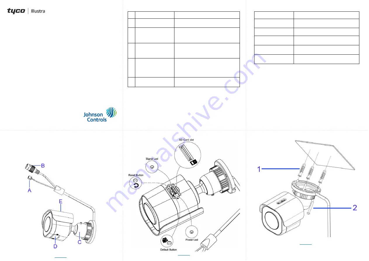
Table 2: Camera internal interface descriptions
Name
Description
Reset Button
Press and release to reboot the camera.
Signal LED (RED)
Indicates network data is being
transmitted.
Micro SD card slot
Insert a micro SD card into the slot for
recording and file storage.
Power LED (GREEN)
Indicates camera is powered on.
Default Button
Press the button for 6 seconds to restore
to the factory default settings.
Mounting the camera
A. Place the mounting template on the mounting surface and drill three
6mm (0.25’’)
holes.
B. Insert the three plastic anchors (1) (Figure 3) into the three holes.
C. Place the camera on the mounting surface and align the three holes on
the camera with the three holes on the mounting surface.
D. Insert the three tapping screws (2) (Figure 3) into the three holes on the
camera body and using the screw driver securely attach the camera to
the wall / ceiling.
Security
Q
uick
S
tart
G
uide
(8200-1929-02_A0)
Essential Gen4 2MP Fixed & Varifocal Bullet Cameras
In the box
1 x Essentials Outdoor IR Bullet camera
1 x Printed Quick Start Guide
1 x Torx wrench
3 x Plastic anchors
3 x Tapping screws
1 x Mounting template
1 x T6 Wrench 130mm X 30mm (Varifocal Camera)
Installation tools
Drill
Screwdrivers
Wire cutters
Quick reference
Default IP: 192.168.1.168 (DHCP enabled)
Default Username: admin
Default Password: admin
Power: PoE (IEEE 802.3af Class 3)
Figure 1: Camera parts and connections
Figure 1
Table 1: Camera parts and connections descriptions
Name
Description
A
DC 12V Port
For powering on the camera through the
DC12V power source.
B
RJ-45 Ethernet / PoE
Port
Connect an Ethernet cable terminated
with RJ-45 connector to the PoE RJ-45
port for both power supply and network
connectivity purposes simultaneously.
C
Mounting Bracket
To mount the camera onto different
environments, the mounting bracket is
designed with three axes for flexible
adjustment.
D
Internal Interface Cover
Use a screwdriver to loosen the 2 screws
and open the cover to access the internal
interfaces including the “RESET” and
“DEFAULT” buttons, “Micro SD Card
Slot”, and LED’s.
E
Protection Shield Hood
For minimizing the effects of rain and
sunlight on image quality.
Figure 2: Camera internal interface and descriptions
Figure 2
Mounting the camera (continued)
Figure 3


