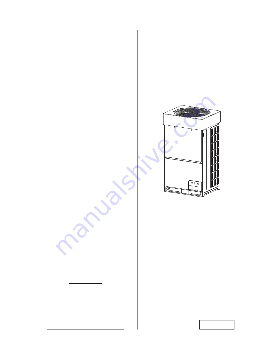
background image

P00877Q

Models:

Outdoor Units

(Low Ambient VRF Heat Pump);

<208/230V >

 (H,Y)VAHP072B31CW, 

(H,Y)VAHP096B31CW, 

 (H,Y)VAHP144B31CW, 

(H,Y)VAHP168B31CW, 

 (H,Y)VAHP192B31CW, 

(H,Y)VAHP288B31CW 

 < 460V >

 (H,Y)VAHP072B41CW, 

(H,Y)VAHP096B41CW, 

 (H,Y)VAHP144B41CW, 

(H,Y)VAHP168B41CW,

 (H,Y)VAHP192B41CW, 

(H,Y)VAHP288B41CW

IMPORTANT:

READ AND UNDERSTAND
THIS MANUAL BEFORE
USING THIS HEAT PUMP
AIR CONDITIONER.
KEEP THIS MANUAL FOR
FUTURE REFERENCE.

Installation

and

Maintenance

Manual

INVERTER-DRIVEN

MULTI-SPLIT SYSTEM

HEAT PUMP

AIR CONDITIONERS

Содержание (H,Y)VAHP072B31CW

Страница 1: ...CW H Y VAHP288B31CW 460V H Y VAHP072B41CW H Y VAHP096B41CW H Y VAHP144B41CW H Y VAHP168B41CW H Y VAHP192B41CW H Y VAHP288B41CW IMPORTANT READ AND UNDERSTAND THIS MANUAL BEFORE USING THIS HEAT PUMP AIR CONDITIONER KEEP THIS MANUAL FOR FUTURE REFERENCE Installation and Maintenance Manual INVERTER DRIVEN MULTI SPLIT SYSTEM HEAT PUMP AIR CONDITIONERS ...

Страница 2: ......

Страница 3: ...J DLUÀRZ RQ ZLUHG FRQWUROOHU IRU PDLQWDLQLQJ LQGRRU FRPIRUW Important Notice Ɣ Johnson Controls Inc pursues a policy of continuing improvement in design and performance in its products As such Johnson Controls Inc reserves the right to make changes at any time without prior notice Ɣ Johnson Controls Inc cannot anticipate every possible circumstance that might involve a potential hazard Ɣ This heat...

Страница 4: ...ase order 3 The standard utilization for this unit is explained in these instructions Use of this equipment for purposes other than what it designed for is not recommended 4 Please contact your local agent or contractor as any issues involving installation performance or PDLQWHQDQFH DULVH LDELOLW GRHV QRW FRYHU GHIHFWV RULJLQDWLQJ IURP XQDXWKRUL HG PRGL FDWLRQV performed by a customer without the ...

Страница 5: ...3 2 Condensate Treatment 23 6 Refrigerant Piping Work 24 6 1 Piping Materials 25 6 2 Piping Connection Work 28 6 2 1 Stop Valve 28 6 2 2 Piping Connection Method 29 6 3 Piping Work between Outdoor Units 32 6 4 Piping Size between Outdoor Units 35 6 5 Piping Size and Multi Kit Selection 37 6 6 Multi Kit Connection 43 7 Electrical Wiring 44 7 1 General Check 45 7 2 Electrical Wiring Connection 45 7 ...

Страница 6: ......

Страница 7: ...ible damage or injury that might occur in an earthquake if the unit is not installed correctly injuries may occur due to a falling unit Ɣ Use appropriate Personal Protective Equipment PPE such as gloves and protective goggles and where appropriate have a gas mask nearby Also use electrical protection equipment and tools suited IRU HOHFWULFDO RSHUDWLRQ SXUSRVHV HHS D TXHQFKLQJ FORWK DQG D UH H WLQJ...

Страница 8: ...FK PD FDXVH OHDNV Ɣ Be sure the drain hose discharges water properly If connected incorrectly it may cause leaks Ɣ Do not install the unit in any place where oil can seep onto the units such as table or seating areas in restaurants and so forth For these locations or social venues use specialized units with oil resistant features built into them In addition use a specialized ceiling fan designed f...

Страница 9: ...at have been approved for use in the unit s intended home country or market Johnson Controls distributors similarly are only authorized to provide refrigerants that have been approved for use in the countries or markets they serve The refrigerant used in this unit LV LGHQWL HG RQ WKH XQLW V IDFHSODWH DQG RU LQ WKH DVVRFLDWHG PDQXDOV Q DGGLWLRQV RI UHIULJHUDQW LQWR this unit must comply with the co...

Страница 10: ...DNH WKH IROORZLQJ SUHFDXWLRQV WR UHGXFH WKH ULVN RI HOHFWULF VKRFN UH RU explosion resulting in serious injury or death Ɣ Highly dangerous electrical voltages are used in this system Carefully refer to the wiring diagram and these instructions when wiring Improper connections and inadequate grounding can cause serious injury or death Ɣ Perform all electrical work in strict accordance with this ins...

Страница 11: ...intenance for electrical parts Check to ensure that no residual voltage is present after disconnecting the power source Ɣ Do not clean with or pour water into the controller as it could cause electric shock and or damage the unit Do not use strong detergent such as a solvent Clean with a soft cloth Ɣ Check that the ground wire is securely connected Do not connect ground wiring to gas piping water ...

Страница 12: ...nit please contact your distributor NOTE inch mm Accessory 72 Type 96 Type Remarks Cable Clamp For Fixing Power Supply Wiring and PVC Tube x 1 x 1 Cable Band 5 5 Screw One for Fixing Cord Clamp Tow for Spare 3 3 PVC Tube 2 2 ID 1 2 12 Rubber Bushing For Power Supply Wiring Bottom Base 1 1 OD 2 5 16 58 For Communication Cable Piping Cover 2 2 OD 1 1 2 38 3 Before Installation ...

Страница 13: ... Gas Leak Detector 3 Vacuum Pump 10 Brazing Kit 18 Level 4 Refrigerant Gas Hose 11 Hexagon Wrench 19 Crimper for Solderless Terminals 5 Megohmmeter 12 Wrench 20 Hoist for Indoor Unit 6 Copper Pipe Bender 13 Scale 21 Ammeter 7 Manual Water Pump for Indoor Unit 14 Charging Cylinder 22 Voltage Meter 15 Gauge Manifold 3 2 Necessary Tools and Instrument List for Installation ...

Страница 14: ...ntamin Blow nitrogen during brazing Prevention from Oxidation during Brazing Lubrication Oil for Flare Surface O Use a synthetic oil which is equivalent to the oil used in the refrigeration cycle Synthetic oil absorbs moisture quickly Applying Oil to the Flared Surface Vacuum Drying O Refrigerant Charge Refrigerant Cylinder O Check refrigerant cylinder color Liquid refrigerant charging is required...

Страница 15: ... 15 88 1 5 32 29 3 4 19 05 1 13 32 36 NOTE Do not use a thin joint other than the ones shown in the table at the left NOTES Do not use the pipe that allowable pressure is less than 601 psi 4 15MPa The reference value of the refrigerant piping thickness is indicated in the table at left Do not use the pipe which is considerably different from the reference value B Flare Nut x Piping Thickness and M...

Страница 16: ... D 12 15 32 D 5 8 5 16 8 0 002 0 018 0 05 0 45 12 D 16 5 8 D 31 32 13 32 10 16 D 25 31 32 D 1 3 8 15 32 12 0 002 0 022 0 05 0 55 25 D 35 1 3 8 D 1 25 32 9 16 14 35 D 45 x Processing at Brazing Connection To prevent gas leakage at the brazing connection refer to the table for the insertion depth and the gap for joint pipe B D A ...

Страница 17: ...city MBH 144 168 192 288 Model H Y VAHP144B31CW H Y VAHP168B31CW H Y VAHP192B31CW H Y VAHP288B31CW Combination H Y VAHP072B31CW H Y VAHP096B31CW H Y VAHP096B31CW H Y VAHP096B31CW H Y VAHP072B31CW H Y VAHP072B31CW H Y VAHP096B31CW H Y VAHP096B31CW H Y VAHP096B31CW 460V Base Unit Capacity MBH 72 96 Model H Y VAHP072B41CW H Y VAHP096B41CW Combination of Base Units Capacity MBH 144 168 192 288 Model H...

Страница 18: ...door air temperature is lower than 14o F 10o C select the combination of indoor units and outdoor unit as the total capacity of indoors not to exceed the capacity of outdoor unit Table 3 2 System Combination NOTES 1 The connectable indoor unit capacity ratio can be calculated as follows Connectable Indoor Unit Capacity Ratio Total Indoor Unit Capacity Total Outdoor Unit Capacity 2 For the system u...

Страница 19: ...n Indoor Unit Side Indoor Unit Side Piping Connection Kit 1 Piping Connection Kit 1 Piping Connection Kit 2 Piping Connection Kit 2 Maintain a straight line distance of 19 11 16 inch 500mm or more for piping after the piping connection kit Outdoor Unit A Outdoor Unit B Outdoor Unit C Outdoor Unit C Outdoor Unit B Outdoor Unit A NOTICE I WKH DUUDQJHPHQW IRU RXWGRRU XQLWV LV LQFRUUHFW LW PD FDXVH ÀR...

Страница 20: ...DFFXPXODWH VXFK DV QHDU D KRW tub or hot spring Ɠ KHUH GHQVH VDOW ODGHQ DLUÀRZ LV KHDY VXFK DV LQ FRDVWDO UHJLRQV Ɠ Where the air quality is of high acidity Ɠ Where harmful gases can be generated from decomposition Ɣ During heating or defrosting operation drain water is discharged Provide adequate drainage around the foundation If installing the unit on a roof or a balcony provide the additional d...

Страница 21: ...ry clearance indicated in the diagram above For walls on more than two sides secure adequate clearance for service access space as shown in the following illustrations If the space between the unit and an obstacle above the unit is less than 59 1 16 inch 1 500mm or the space above the unit is closed set up the duct at the air outlet side in order to prevent short circuit Make sure there is enough ...

Страница 22: ... Space Front Side Front Side 1 If the snow protection hood optional part or the air outlet duct field supplied is adopted a minimum spacial clearance of 1 15 16 inch is required Min 11 13 16 h1 2 Unit inch Min 3 8 1 Front Side Top View Min 19 11 16 h2 2 No limit for side wall height Min 11 13 16 Min 3 8 1 Front Side Top View No limit for side wall height Min 11 13 16 Min 15 3 4 Min 7 7 8 Front Sid...

Страница 23: ...m spacial distance between each unit group 3 Walls on Four Sides Single Installation Installation in the Same Direction Rear to Rear Installation Multiple Serial Installation One Group Max Six Outdoor Units Min 3 3 ft Top View Front Side No limit for side wall height No limit for side wall height Min 7 7 8 Min 7 7 8 Min 19 11 16 h2 2 Min 7 7 8 Min 7 7 8 Front Side Min 35 7 16 Min 31 1 2 2 Open Min...

Страница 24: ...handling Secure with two sling belts when hoisting the outdoor unit with a crane Ɣ 7UDQVSRUWDWLRQ DQG DQGLQJ LUH To protect the unit do not remove any packing R QRW VWDFN RU SODFH DQ PDWHULDO on top of the product Apply banding wire to both sides of the packaged unit as shown at right Sling Belt Wooden Skid Base INCORRECT Sling Belt Square Hole Apply sling belts through square holes Sling Belt Pos...

Страница 25: ...Sling Belt Slots Slots Sling Belt Position INCORRECT CORRECT Angle of sling belt is more than 60o Min 6 6 ft 2 0m Top corners Attach four 5 8 inch 15mm thick corrugated corner padding as shown Bottom corners Attach four 5 8 inch 15mm thick cardboard padding on both sides at this point for protection Do not apply any force to surface Both Sides Do not remove corrugated paper frame and plastic bands...

Страница 26: ...nto the slots at the unit side panels The unit can sustain damage Do not apply excessive force to the squared slots with forks or other materials The bottom of the unit can become deformed Do not push the bottom base with forks Do not use a roller XULQJ WUDQVSRUWDWLRQ GR QRW DOORZ WKH EDFNUHVW RI WKH IRUNOLIW WR FRPH LQWR FRQWDFW ZLWK WKH XQLW Sudden forward movement on the forklift can cause dama...

Страница 27: ...in the face of strong winds and seismic events Provide a concrete foundation as shown below Do not use a concrete foundation such as seen here The footing for the outdoor unit can become deformed Width Depth INCORRECT CORRECT Front Side of Unit Foot Front Side of Unit Foot Foundation Foundation Right Side and Left Side Front Side and Rear Side Details of Installing Anchor Bolt Place the edge of th...

Страница 28: ... to Figure 5 3 for the location of holes for anchor bolts Figure 5 3 Positions of Anchor Bolts Unit inch 5 3 8 37 5 16 5 3 8 28 11 16 1 9 16 1 4 1 1 2 x 9 16 Long Hole Hole for Anchor Bolt M12 Pitch for Anchor Bolts Pitch for Anchor Bolts 18 11 16 Min 3 1 8 Min 3 1 8 Vibration Proof Mat 3 portions of each front and rear ...

Страница 29: ...n slightly from screw holes Provide a second condensation drainage pan under the outdoor unit as necessary Name Model Drain Adaptor DBS TP10A Component Formation of Drain Adaptor Model Parts Name Material Color Qty Application DBS TP10A Drain Adaptor PP Black 2 Connecting for Drain Piping Drain Cap PP Black 2 Cover for Drain Hole Rubber Cap CR Black 4 Sealing for Adaptor and Cap Unit inch x Drain ...

Страница 30: ...may rupture due to an excessive refrigerant pressure Pay close attention to the piping thickness when using copper refrigerant piping The thickness of copper refrigerant piping differs depending on its material x KHFN WR HQVXUH WKDW QR SUHVVXUH H LVWV LQVLGH WKH VWRS YDOYH EHIRUH UHPRYLQJ WKH ÀDQJH x Ensure that the corresponding pipe connections for the liquid and gas piping are properly FRQQHFWH...

Страница 31: ...LGDQW ZKLFK FDQ FRUURGH SLSHV DQG GHJUDGH WKH UHIULJHUDQW RLO 8VH D W SH RI ÀX ZLWK D ORZ FKORULQH FRQFHQWUDWLRQ 5HPRYH DOO ÀX FRPSOHWHO DIWHU FRPSOHWLQJ EUD LQJ ZRUN NOTICE To avoid oxidation and scaling perform brazing at the appropriate temperature NOTES 1 Make sure to use nitrogen Nitrogen gas pressure shall be 2 9 psi 0 02 MPa or less DO NOT use the following gases Oxygen 7KLV LV ÀDPPDEOH DQG...

Страница 32: ... 5 8 inch 15 88 mm 50 2 60 5 ft lbs 68 82 N m 3 4 inch 19 05 mm 73 8 88 5 ft lbs 100 120 N m NOTE As for the tightening torque for liquid stop valve according to Section 6 2 1 Stop Valve Liquid Valve of the tightening torque table 4 When the temperature and humidity inside the ceiling exceed 80o F 27o C RH80 apply additional insulation of approximately 3 8 inch 10mm in thickness to the accessory i...

Страница 33: ...ccur NOTE Gas Piping Installing Part for Piping Liquid Piping NOTICE When assembling piping onsite with hidden elbow or socket joints provide a service access doorway to facilitate close up examination of interconnecting components Ɣ DXWLRQ IRU QVWDOOLQJ DQG 6HFXULQJ 3LSLQJ Table 6 1 Piping Size of Outdoor Unit inch mm Outdoor Unit Capacity MBH Gas Liquid 72 96 7 8 22 2 3 8 9 52 144 192 1 1 8 28 5...

Страница 34: ... piping 3 Cut the end of the closing pipe and ensure that no residual gas exists inside the gas piping 5HPRYH WKH FORVLQJ SLSH IURP WKH EUD LQJ SRUWLRQ ZLWK D WRUFK H FDUHIXO WKDW WKH ÀDPH GRHVQ W EXUQ the stop valve Ɣ 5HPRYH JDV LQVLGH WKH FORVLQJ SLSH EHIRUH WKH EUD LQJ ZRUN LV SHUIRUPHG I WKH EUD LQJ OOHU PHWDO PHOWV ZLWK UHVLGXDO JDV LQVLGH WKH SLSLQJ ZLOO H SORGH DQG LQMXULHV FDQ result Ɣ R Q...

Страница 35: ...the same refrigerant system Ɣ LUPO VHFXUH WKH SLSLQJ LQ RUGHU WR DYRLG YLEUDWLRQ DQG H FHVVLYH force exerted on the valve 2 Follow the installation procedures in Section 6 2 1 3 Connect the piping in accordance with Figures 6 1 and 6 2 on the following page 4 Seal the gap between the bottom base or front piping cover and pipes with the insulation 1 Piping can be installed in three directions front...

Страница 36: ...on 6 11 16 170 Refrigerant Liquid Piping Connection 13 3 8 340 Refrigerant Liquid Piping Connection 8 1 16 205 Refrigerant Gas Piping Connection φ7 8 22 2 Refrigerant Gas Piping Connection φ3 8 9 52 Refrigerant Liquid Piping Connection Konckout Square Hole for Piping Cover 3 7 16 88 5 11 16 145 8 1 16 205 3 3 8 85 3 1 4 82 9 13 16 250 5 1 8 130 4 1 4 108 5 3 16 132 4 5 16 110 7 1 2 190 2 9 16 65 1...

Страница 37: ... RQQHFWLRQ NOTES QVXUH WKDW WKH FORVLQJ SLSH RI WKH JDV VWRS YDOYH LV UHPRYHG UVW 5HIHU WR LJXUH DERYH IRU WKH ÀDULQJ ZRUN Flaring Stop Valve Gas Stop Valve Liquid Liquid Pipe Field Supplied Gas Pipe Field Supplied 90o Elbow A Field Supplied ...

Страница 38: ...learance of 11 13 16 inch 300mm between the piping connection kit and the bottom of the outdoor unit Also install an oil trap minimum 7 7 8 inch 200mm between the piping connection kit and the outdoor unit 6 3 Piping Work between Outdoor Units Outdoor Unit B Outdoor Unit A Outdoor Unit C Piping Connection Kit 1 Piping Connection Kit 2 L L C A B L Indoor Unit Side Outdoor Unit B Outdoor Unit A Outd...

Страница 39: ...WKH JXUH 5 For servicing if the pipe is installed in front of the outdoor unit make sure minimum clearance of 19 11 16 inch 500mm between the outdoor unit and piping connection kits When the compressor is replaced minimum clearance of 19 11 16 inch 500mm is required The refrigerant system may be damaged if the slope of the piping connection kit exceeds 15o NOTICE Less than 6 6 ft Less than 6 6 ft ...

Страница 40: ...ssory Pipe L Shape Accessory Pipe L Shape Accessory Pipe L Shape Accessory Pipe L Shape Liquid Piping Field Supplied Liquid Piping Field Supplied Liquid Piping Field Supplied Gas Piping Field Supplied Gas Piping Field Supplied Gas Piping Field Supplied Foundation for Outdoor Unit Accessory Pipe Z Shape Accessory Pipe Z Shape Piping Connection Kit 1 Liquid Piping Connection Kit 1 Gas Base Field Sup...

Страница 41: ...8 15 88 5 8 15 88 b Gas 7 8 22 2 7 8 22 2 7 8 22 2 Liquid 3 8 9 52 3 8 9 52 3 8 9 52 c Gas 7 8 22 2 7 8 22 2 7 8 22 2 Liquid 3 8 9 52 3 8 9 52 3 8 9 52 Install the outdoor unit and piping connections in accordance to whatever is applicable to your situation Refer to the table for the outdoor unit model the piping connection kit model and the piping diameter Base Unit Two Units Combination To Indoo...

Страница 42: ...ee Units Combination Indoor Unit on Left Side Indoor Unit on Right Side Install the outdoor unit and piping connections in accordance to whatever is applicable to your situation Refer to the table for the outdoor unit model the piping connection kit model and the piping diameter Outdoor Unit A To Indoor Units Outdoor Unit B Outdoor Unit C Piping Connection Kit 1 Piping Connection Kit 2 a c d e b O...

Страница 43: ...ches Model 36 60 4 MH NP224A 36 72 8 MH NP288A Line Branch Header Branch C Line Branch after First Branch Total Indoor Unit Capacity MBH Model 86 MW NP282A2 87 125 MW NP452A2 126 185 MW NP692A2 186 MW NP902A2 NOTE If C Line Branch after First Branch is larger than B First Branch use the same model as B First Branch Multi Kit Optional Parts 1 1 4 4 5 5 5 5 4 5 5 1 3 2 D C C B A Maintain a straight ...

Страница 44: ...U HOG supplied NOTE If the size of 4 Pipe after First Branch is larger than the size of 3 Main Pipe adjust the size of 4 Pipe after First Branch to the same size as 3 Main Pipe 5 Diameter of Pipe between Multi Kit and Indoor Unit Indoor Unit Capacity MBH Gas Liquid 6 15 1 2 12 7 1 4 6 35 1 18 48 5 8 15 88 3 8 9 52 72 3 4 19 05 3 8 9 52 96 7 8 22 2 3 8 9 52 1 When liquid piping length is longer tha...

Страница 45: ... Maximum Piping Length Ex1 a c The actual piping length between the stop valve of the outdoor unit or the piping connection kit1 and the terminal indoor unit Ex2 f h Piping Length The actual length of pipe that takes no account for equivalent lengths for pressure drops of elbows Equivalent Piping Length The combination of the straight pipe length plus the equivalent length of elbows and other pres...

Страница 46: ...ls 2 The piping length between outdoor units should be La Lb Lc 32 8 ft 10m If the piping length is incorrect there may be a failure of outdoor units caused by a refrigerant back up 3 Maintain a straight line distance of 19 11 16 inch 500mm or more for piping after the piping connection kit 4 The condition of refrigerant piping installation is different depending on the connected number of indoor ...

Страница 47: ...131 2 ft 40m Example 2 Installation without Main Piping Branch 7 3LSLQJ OHQJWK IURP WKH 0XOWL LW DW WKH UVW EUDQFK WR WKH WHUPLQDO LQGRRU XQLW LV ZLWKLQ IW 90m 1 If the pipe length L2 is over 131 2 ft 40m the size of gas and liquid pipes b d and f should be selected according to Table 4 below Diameter of Pipe after First Branch If the size of a is smaller than the size of b after selecting the siz...

Страница 48: ...nd operating limit in overload operation 2 For the system under which all the indoor units are not supposed to operate simultaneously the total indoor unit capacity is available 100 or more against the outdoor unit capacity Refer to Table 3 2 System Combination for detail 3 When operating the outdoor unit in cold area with temperatures of 14o F 10o C or under the high heating load conditions the t...

Страница 49: ...ch Connection Branch Pipe Branch Pipe Straight Length Min 1 6 ft Main Pipe Branch Connection Branch Pipe Branch Pipe Main Pipe Branch Connection Branch Pipe Branch Pipe Bending Radius Min 1 6 ft CORRECT CORRECT CORRECT INCORRECT Upper Side Upper Side Upper Side Upper Side Piping Form from Multi Kit to Indoor Unit Outdoor Unit Outdoor Unit Multi Kit Ex Recommended To prevent pipe damage use bending...

Страница 50: ...13 3 to 17 0 ft lbs 18 0 to 23 0 N m Ɣ 6HW 6 RQ WKH 3 DFFRUGLQJ WR HDFK SRZHU VXSSO VKRZQ LQ WKH JXUH EHORZ Ɣ 8VH WKH VSHFL HG FDEOHV IRU ZLULQJ EHWZHHQ WKH RXWGRRU XQLW DQG LQGRRU XQLWV 6HOHFWLQJ LQFRUUHFW FDEOHV ZLOO FDXVH DQ HOHFWULF VKRFN RU D UH RPPXQLFDWLRQ FDEOLQJ VKDOO EH D PLQLPXP RI AWG18 0 82mm2 2 Conductor Stranded Copper Shielded cable must be considered for applications and routing i...

Страница 51: ...en shielded cabling is applied proper bonding and termination of the cable shield is required as per Johnson Controls guidelines Plenum and riser ratings for communication cables must be considered per application and local code requirements x In an instance where the power source for the packaged air conditioner is supplied from the same power transformer as the device with high electricity consu...

Страница 52: ...or Unit Power Source AC 3 208 230V 60Hz AC 3 460V 60Hz 1 2 1 2 1 3 3 3 4 6 5 5 6 5 7 8 8 7 7 7 4 5 4 Indoor Unit Side S GFCI Indoor Unit Power Source AC 1 208 230V 60Hz Pull Box Pull Box GFCI Ground Fault Circuit Interrupter S Main Switch and Fuse 2 Power Supply Wiring O U Ground Wiring O U Communication Cable O U I U Communication Cable O U O U 8 Power Supply Wiring I U Ground Wiring I U S S GFCI...

Страница 53: ...ll be a minimum of AWG18 0 82mm2 2 Conductor Stranded Copper Shielded cable must be considered for applications and routing in areas of high EMI and other sources of potentially excessive electrical noise to reduce the potential for communication errors When shielded cabling is applied proper bonding and termination of the cable shield is required as per Johnson Controls guidelines Plenum and rise...

Страница 54: ...4 Tighten screws for the terminal block according to the following table Required Tightening Torque Size Tightening Torque M4 0 7 to 1 0 IWÂOEV 1 0 to 1 3 1ÂP M5 1 5 to 1 8 IWÂOEV 2 0 to 2 4 1ÂP M6 3 0 to 3 7 IWÂOEV 4 0 to 5 0 1ÂP M8 6 6 to 8 1 IWÂOEV 9 0 to 11 0 1ÂP M10 13 3 to 17 0 IWÂOEV 18 0 to 23 0 1ÂP Secure with a cable clamp PVC Tube VW 1 600V Accessory Cable Clamp For Securing Power Suppl...

Страница 55: ...onnect a power supply wiring to each indoor unit group connected to the same outdoor unit Total operating current be less than 12A Connect a Ground Fault Circuit Interrupter GFCI fuse and main switch S to each indoor unit group 3 Connect the communication cable between indoor units and outdoor units as shown in Figure 7 1 4 Connect the communication cables in the same refrigerant system unit If th...

Страница 56: ...tdoor units in the same refrigerant system to the terminals 3 and 4 on TB2 x Communication Cabling NOTES 1 For the combination units DSW settings of Main and Sub are required 2 An alarm occurs if the communication cables between main outdoor unit and sub outdoor units are connected to the terminals 1 and 2 for H LINK system 3 In an alarm is triggered on the LCD of Main outdoor unit follow the 7 se...

Страница 57: ...ull Box GFCI GFCI GFCI GFCI GFCI S S S Outdoor Unit A Main Ground Ground Outdoor Unit B Sub Controller Cable Controller Cable Wired Controller Wired Controller No 0 System Indoor Units No 1 System Indoor Units 1 208 230V 60Hz TB Terminal Block PCB Printed Circuit Board Field Wiring Communication Line DC5V Non Pole Communication H LINK System Field Supplied Optional Accessory 3 208 230V 60Hz 460V 6...

Страница 58: ...Ref Cycle No Setting DSW3 Setting Before Shipment DSW10 Transmission Setting Power Supply Setting and Service Setting For End Resistance Cancellation End Resistance Cancellation 2 1 ON 2 1 ON Setting Before Shipment 208V 230V Unit 230V Setting Before Shipment 460V Unit 460V Setting Before Shipment 208V Unit 230V 460V Unit 208V 230V 460V Test Run and Service Setting DSW4 For Test Run Function Setti...

Страница 59: ... Base Unit Unit A No 0 Unit B No 1 Unit C No 2 1 2 3 4 ON OFF 1 2 3 4 ON OFF 1 2 3 4 ON OFF 1 2 3 4 ON OFF Maximum Number of Connectable Outdoor Units and Indoor Units for H LINK II Outdoor Unit 64 Indoor Unit 160 NOTE For installing the outdoor unit and the indoor unit on the same communication cable which cannot be used for H LINK II maximum number of connectable indoor units is 128 0 7 9 5 8 6 ...

Страница 60: ...W10 to the OFF position except the main outdoor unit A In a situation of one refrigerant system in the same H LINK II set all No 1 pin of DSW10 in the OFF position except the main outdoor unit A 1 2 1 2 ON OFF ON OFF Before Shipment Cancellation DSW10 Setting of End Terminal Resistance Voltage DSW7 Setting 208V 230V 460V 1 2 3 4 ON OFF 1 2 3 4 ON OFF 1 2 3 4 ON OFF 1 2 DSW10 1 2 DSW10 1 2 DSW10 Co...

Страница 61: ...op Defrost Signal 5 Forced Stoppage 6 Demand Current Control 40 7 Demand Current Control 60 8 Demand Current Control 70 9 Demand Current Control 80 10 Demand Current Control 100 11 Low Noise Setting 1 12 Low Noise Setting 2 13 Low Noise Setting 3 0 No Setting No Setting Item SEG2 SEG1 SET 1 Input Setting 1 CN17 1 2 pin 2 Input Setting 2 CN17 2 3 pin 3 Input Setting 3 CN18 1 2 pin 4 Output Setting ...

Страница 62: ...er etc when controlling the stop valve in a cold area The spindle O ring will harden at low temperature causing the O ring material to contract by volume and refrigerant leakage can occur c Do not apply excessive force after fully opening the spindle Tightening Torque 3 7 ft lbs 5 0 N m A back seat hard stop is not provided allowing complete removal of the valve stem G 7LJKWHQ FDSV VHFXUHO DFFRUGL...

Страница 63: ...G OLQH VLGH If not performed in this manner the expansion valve for the outdoor unit or indoor unit can close up making any airtight test impossible Be sure to use nitrogen gas for the airtight test If other gases such as oxygen gas acetylene gas or ÀXRURFDUERQ JDV DUH DFFLGHQWDOO XVHG LW PD FDXVH DQ H SORVLRQ RU JDV DVSK LDWLRQ Insulation Work 1 Securely insulate the gas piping side and liquid pi...

Страница 64: ...at the gas valve and liquid stop valve are fully closed Charge the additional refrigerant from the check joint of liquid stop valve acceptable error must be within 1 1 lbs 0 5 kg 3 After refrigerant has been charged fully open the liquid stop valve and gas stop valves NOTE Gas remaining at the O ring or screw component may emit a hissing sound when removing the spindle cap However this is not leak...

Страница 65: ...efrigerant quantity according to Table 8 1 If not a compressor may be damaged due to an excess or LQVXI FLHQW UHIULJHUDQW FKDUJH Refrigerant charge from check joint of gas stop valve may lead to compressor failure Be sure to charge refrigerant from the check joint of liquid stop valve Insulate the liquid piping and gas piping completely to avoid decreasing of performance and dewing on the surface ...

Страница 66: ...3 Calculation Method for Additional Refrigerant Charge W3 lbs If the capacity of combined Indoor Unit is larger than 072 MBH the additional refrigerant charge must be 2 2 lbs unit 2 2 lbs unit lbs 4 W4 The Ratio of Indoor Unit Connection Capacity Indoor Unit Total Capacity Outdoor Unit Capacity Additional Charge W4 lbs Determine the ratio of indoor unit connection capacity Condition Refrigerant Am...

Страница 67: ...TE When refrigerant is recovered or charged due to repairs operating or adjusting the unit record the refrigerant quantity again NOTICE 1 PLVVLRQV RI WKH ÀXRURFDUERQV ZLWKRXW DQ UHDVRQ DUH SURKLELWHG 2 RU GLVSRVDO DQG PDLQWHQDQFH RI WKLV SURGXFW UHFRYHU RI ÀXRURFDUERQV LV UHTXLUHG 8 5 Automatic Simple Judgment System for Refrigerant Amount 1 This function is applicable when outdoor air temperature...

Страница 68: ...acity ratio 30 indoor units capacity ratio or less Especially if the indoor ambient air temperature is 15 or less the total indoor unit operation capacity will be 30 indoor units capacity ratio or less and if this is the case sometimes this refrigerant quantity check cannot be performed 6 Is switch No 4 pin of DSW4 compressor forced stoppage OFF 1 Refrigerant quantity check operation can be perfor...

Страница 69: ...Attention Regarding Refrigerant Gas Leakage Pay attention to the critical gas concentration to avoid accidental refrigerant gas leakage before installing air conditioning systems Critical Concentration lbs ft3 Totally Charged Refrigerant Quantity in System lbs Room Space for each Indoor Unit ft3 0 019 lbs ft3 0 3 kg m3 If the calculated critical concentration is higher than 0 019 lbs ft3 0 3kg m3 ...

Страница 70: ...s Do not impress the voltage on the terminals for communication lines Outdoor Unit TB2 1 2 3 4 Indoor Unit TB2 A B 1 2 Otherwise failure can result 3 Verify that each wire L1 L2 and L3 is correctly connected at the power source If any one of those is incorrectly connected the unit will not operate and the wired controller will display the alarm code 05 In this case check and change the phase of th...

Страница 71: ...e compressor cables from the inverter PCB Then turn on the main power to apply current to the crankcase heater IWHU DSSO LQJ FXUUHQW IRU PRUH WKDQ WKUHH KRXUV PHDVXUH LQVXODWLRQ UHVLVWDQFH DJDLQ HSHQGLQJ on the air conditions length of piping or refrigerant conditions it may be necessary to apply the current for a longer period of time I WKH URXQG DXOW LUFXLW QWHUUXSWHU LV DFWLYDWHG FKHFN WKH UHFR...

Страница 72: ...QFWLRQ may be activated Cancel Test Run mode and reset it Ɣ If the indicated number is not equal to the actual number of connected indoor units the auto address function is not performed correctly due to incorrect wiring or electronic noise EMI Turn OFF the power supply and correct the wiring after checking the following areas Do not repeat turning ON and OFF within 10 seconds The power supply for...

Страница 73: ...LV LV DQ LQGLFDWLRQ WKDW the system is searching for irregularities in communication between indoor units and the wired controller This could boil down to loose or disconnected wires components and incorrect wiring Ɣ VPDOO VRXQG PD EH KHDUG IURP WKH RXWGRRU XQLW DIWHU WXUQLQJ 21 DW WKH SRZHU VRXUFH because the electrical expansion valve is activated to adjust the opening Therefore there is no mech...

Страница 74: ...r is canceled However the test run function of the outdoor unit is not canceled Check to ensure that the No 1 pin of DSW4 of the outdoor unit PCB is turned OFF If multiple indoor units are connected with one wired controller perform the test run operation individually for each refrigerant system one by one Then make sure to turn the power source OFF for the indoor units in other refrigerant system...

Страница 75: ... Inlet DB o F WB o F Outlet DB o F WB o F 7 Check Refrigerant Temperature Liquid Temperature o F Discharge Gas Temperature o F 8 Check Pressure Discharge Pressure Psi Suction Pressure Psi 9 Check Voltage Rated Voltage V Operating Voltage L1 L2 V L1 L3 V L2 L3 V Starting Voltage V V Vm 10 Check Compressor Input Running Current Input kW Running Current A 11 Is the refrigerant charge adequate 12 Do t...

Страница 76: ...Refrigerant Charge Failure of Thermistor Incorrect Wiring Incorrect Piping Connection Expansion Valve Locking at Opened Position Disconnect Connector 08 Increase in Discharge Gas Temperature Insufficient Refrigerant Charge Pipe Clogging Failure of Thermistor Incorrect Wiring Incorrect Piping Connection Expansion Valve Locking at Closed Position Disconnect Connector 0A Communication Problem between ...

Страница 77: ...ice Overload Operation Clogging Short Pass Pipe Clogging Excessive Refrigerant Inert Gas Mixing 47 Activation of Low Pressure Decrease Protection Device Vacuum Operation Protection Insufficient Refrigerant Refrigerant Piping Clogging Expansion Valve Locking at Open Position Loose Connector 48 Activation of Inverter Overcurrent Protection Device Overload Operation Compressor Failure 51 Sensor Proble...

Страница 78: ...Automatic Reset Non Adjustable psi MPa Pressure Switch for each compressor Cut Out psi 7 7 21 21 MPa 0 05 0 05 0 15 0 15 Cut In psi 464 21 464 21 MPa 3 20 0 15 3 20 0 15 For Inverter Compressor Automatic Reset Non Adjustable Over Current Inverter Current Protection Control A Breaker A Over Heat Automatic Reset Non Adjustable for 5sec o F o C for 10min o F o C For Fixed Speed Compressor Automatic R...

Страница 79: ......

Страница 80: ...P00877Q Code No LIT 12012285 Issued March 2016 2016 Johnson Controls Inc ...

Отзывы: