background image


Operating Instructions and Parts Manual 

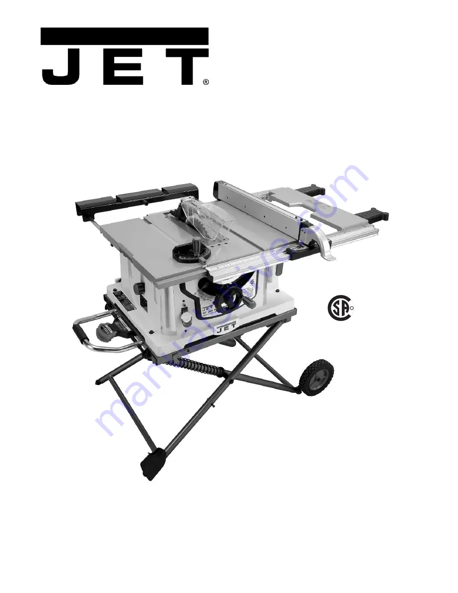
10" Job Site Table Saw 

Benchtop Series – Model No. JBTS-10MJS 


WALTER MEIER (Manufacturing) Inc. 

427 New Sanford Road 
LaVergne, Tennessee 37086 

Part No. M-707000 

Ph.: 800-274-6848 

Revision A3  10/2010 

www.waltermeier.com 

Copyright © 2010 Walter Meier (Manufacturing) Inc. 

C

US

R

  174315

Summary of Contents for JBTS-10MJS

Page 1: ...able Saw Benchtop Series Model No JBTS 10MJS WALTER MEIER Manufacturing Inc 427 New Sanford Road LaVergne Tennessee 37086 Part No M 707000 Ph 800 274 6848 Revision A3 10 2010 www waltermeier com Copyright 2010 Walter Meier Manufacturing Inc C US R 174315 ...

Page 2: ...ation postage prepaid to a location designated by us For the name of the location nearest you please call 1 800 274 6848 You must provide proof of initial purchase date and an explanation of the complaint must accompany the merchandise If our inspection discloses a defect we will repair or replace the product or refund the purchase price at our option We will return the repaired product or replace...

Page 3: ...Splitter 18 90 and 45 Positive Stop Adjustment 19 Blade Tilt Pointer 19 Blade Parallel to the Miter Slot 20 Adjusting the Miter Gauge 21 Rip Fence Adjustment 21 Rip Fence Indicator 22 Table Extension Scale Pointer 22 Rear Table Extension Adjustment 22 Adjusting the Locking Lever 22 Additional Blade Adjustments 20 Operation 23 Basic Saw Operations 23 Cutting Operations 24 Maintenance 28 Push Stick ...

Page 4: ...icks cement and other masonry products Arsenic and chromium from chemically treated lumber Your risk of exposure varies depending on how often you do this type of work To reduce your exposure to these chemicals work in a well ventilated area and work with approved safety equipment such as face or dust masks that are specifically designed to filter out microscopic particles 10 Do not operate this m...

Page 5: ...proper accessories may be hazardous 27 Maintain tools with care Keep saw blades sharp and clean for the best and safest performance Follow instructions for lubricating and changing accessories 28 Disconnect tools before servicing and when changing accessories such as blades 29 Make sure the work piece is securely attached or clamped to the table 30 Turn off the machine before cleaning Use a brush ...

Page 6: ...tor damage 12 Provide adequate support to the rear and the sides of the saw table for long or wide workpieces 13 Avoid kickbacks work thrown back towards you by keeping the blade sharp the rip fence parallel to the saw blade and by keeping the splitter anti kickback pawls and guards in place aligned and functioning Do not release work before passing it completely beyond the saw blade Do not rip wo...

Page 7: ... the saw blade and rip fence or other fixed object To minimize or prevent injury from kickbacks see the Operating Instructions section Miter Gauge A component that controls the workpiece movement while performing a crosscut of various angles Non Through Cut A sawing operation that requires the lowering of the splitter and removal of the blade guard and kick back pawls resulting in a cut that does ...

Page 8: ...ged or worn cord immediately 115 Volt Operation Only Referring to Figure A As received from the factory your table saw is ready to run at 115 volt operation This table saw when wired for 115 volt is intended for use on a circuit that has an outlet and a plug that looks like the one illustrated in A A temporary adapter which looks like the adapter shown in B may be used to connect this plug to a tw...

Page 9: ...9 Features Figure 1 Features ...

Page 10: ...gure 3 A Blade Guard 1 B Kickback Pawl 1 C Riving Knife 1 D Table Saw 1 E Pedal 1 F Miter Gauge 1 G Stand Assembly 1 H Rear Table Extension 1 J Rear Table Extension Tube 2 K Push Stick 1 L Rip Fence 1 M Roller Wheel 2 Hardware Bags see contents on next page Owner s Manual 1 Warranty Registration Card Tools Supplied for Assembly These items shown in Figure 2 N Blade Wrench O 4mm Hex Wrench P 5mm He...

Page 11: ...c Flat Washer 4 Y Screw 2 aZ oStand Pad 1 AA oSplitter Riving Knife Lock Knob 1 BB oFlat Washer 1 CC oSplitter Riving Knife Plate 1 DD oHandwheel Handle 1 EE oPush Stick Storage Clip 1 FF oPlastic Stop 4 GG oScrew 1 HH oRear Extension Pad 1 Read and understand all assembly instructions before attempting assembly Failure to comply may cause serious injury ...

Page 12: ... to each roller wheel M 4 Attach one roller wheel assembly to the right front leg using the bolt Q the shaft sleeve S and the hex nut T as shown Note Verify that the side of the wheel that has more ribs is facing toward the inside of the stand 5 Attach the other roller wheel to the right rear leg using the same manner 6 Tighten screw Q and hex nut T with two 17mm wrenches Note Do not overtighten b...

Page 13: ...lign the mounting holes of the saw with the two holes drilled in step 2 7 Fasten the saw to the work surface using screws Y Fig 4 provided Do not operate this saw on the floor Doing so is very dangerous Failure to comply may cause serious injury Rear Table Extension Referring to Figure 9 1 Attach the rubber pad HH to the inside of the rear table extension H Thread the screw GG thru the rubber pad ...

Page 14: ... the rear of the saw table 8 Lower the blade to the down position Replace the table insert A and the blade guard Important Do not operate this saw until the blade and blade guard splitter are aligned and in working order Removing the Blade To avoid injury from an accidental start make sure the switch is in the OFF position and the plug is disconnected from the power source outlet Referring To Figu...

Page 15: ... the splitter in this position Kickback pawl installation Figure 12a 6 Place the lock lever B1 on the kickback pawl assembly B in the unlock position 7 Install the kickback pawl B onto the splitter The flat sides of the mounting pin on the kickback pawls should pass though the mounting slot C1 on the splitter C Note Make sure the anti kick back pawls do not get caught between the insert and the gu...

Page 16: ... B Fig 14 and miter gauge C Fig 14 are located on the right side of the saw housing Note Adjust the miter gauge to 45º 60º before putting away in storage Blade wrench Insert the handle of the blade wrench A Fig 14 into the slot located to the right side of the saw housing Blade 1 Loosen and remove the knob A Fig 15 on the left side of the saw housing 2 Place extra blades B Fig 15 onto the bushing ...

Page 17: ... out 2 Pushslowly downward onthe stand A B Fig 17 3 Release the locking handle B Fig 16 4 Rotate the stand hook D Fig 16 onto the stop screw to secure the stand legs into the collapsed position 5 Secure the side extension table H Fig 16 by pushing the cam locking lever F Fig 16 downward Note For convenient storage there are two stand up supports G Fig 16 on the right side of the table saw for supp...

Page 18: ...se the blade to the maximum height by turning the blade elevation handwheel clockwise 2 Remove the blade guard and pawl assembly see Blade Guard Assembly on page 15 3 Adjust the blade to the 90 vertical position by unlocking the blade tilting lock knob and turning the bevel tilting handwheel counterclockwise and then lock into position 4 To see if the blade A and splitter B are correctly aligned l...

Page 19: ...90 to the table If not repeat step 5 8 Check the bevel angle scale If the pointer does not read 0 loosen the screw that secures the pointer adjust to read 0 retighten the pointer screw 45 Stop 1 Disconnect the saw from the power source 2 Raise the blade to the maximum elevation 3 Loosen the blade bevel lock handle Adjust the blade D to the maximum bevel position 45 and retighten the bevel lock han...

Page 20: ...e rear of the saw 8 Carefully move the combination square from position G to C 9 If the ruler touches the marked tooth at the front and rear position E at D B at A no adjustment is needed If not perform the adjustment procedure described in the next section Additional Blade Adjustments Refer to Figure 23 If the front and rear measurements are not the same 1 Remove the combination square C and loos...

Page 21: ...d slide the fence to the desired position then push the handle down to lock 4 To check the rip fence adjustment place the fence along one edge of the miter gauge groove and lock the handle It should be parallel to the miter groove to provide accurate cuts If an adjustment is needed to make it parallel 1 Loosen the two hex bolts C on the top of the rip fence and lift up on the handle F 2 Adjust the...

Page 22: ... should be at 13 inches on the scale when the extension is in the closed position If adjustment is required loosen the holding screw B Fig 27 position the pointer over the 13 inch marker and re tighten the screw Rear Table Extension Adjustment The rear table extension A Fig 28 should be positioned as close as possible to the rear of the table when ripping short material The rear table extension sh...

Page 23: ...ty switch key A and pull it out 4 With the removable safety key removed the switch will not operate 5 If the removable safety key is removed while the saw is running it can be turned OFF but cannot be restarted without inserting the removable safety key A Figure 31 Overload Protection This saw has an overload reset button C Fig 31 that resets the motor after it shuts off due to overloading or low ...

Page 24: ...against the fence and must not be warped twisted or bowed when ripping 1 Remove the miter gauge and store it in the storage compartment in the base of the saw 2 Secure the rip fence to the table 3 Raise the blade so it is about 1 8 in higher than the top of the workpiece 4 Place the workpiece flat on the table and against the fence Keep the workpiece away from the blade 5 Turn the saw ON and wait ...

Page 25: ...ade path in line with the desired cut location 4 Start the saw and wait for the blade C to come up to full speed Never stand directly in line of the saw blade path always stand to the side of the blade that you are cutting on 5 Keep the workpiece B against the face of the miter gauge A and flat against the table Then slowly push the workpiece through the blade 6 Do not try to pull the workpiece ba...

Page 26: ...operation Figure 39 Mitering 0 45 Miter Angle This sawing operation is the same as crosscutting except the miter gauge is locked at an angle other than 90 1 Set the blade B to 0 bevel angle and tighten the blade bevel lock knob 2 Set the miter gauge A at the desired miter angle and lock in position by tightening the miter gauge locking handle 3 Hold the workpiece C firmly against the face of the m...

Page 27: ... on this saw restricts the maximum width of the cut to 13 16 in 5 It is not necessary to install the outside flange A before threading on the arbor nut C for the maximum 13 16 in dado cuts Make sure that the arbor nut C is tight and that at least one thread of the arbor sticks out past the nut 6 Use only the correct number of round outside blades and inside chippers as shown in the dado set s inst...

Page 28: ...m Looseness or play in the blade raising screw rod A should be limited to 1 8 or less 3 If excessive looseness is observed in any other parts of the blade raising mechanism or tilting mechanism take the complete unit to a Service Center Place a small amount of dry lubricant on the bevel gear B The screw rod A must be kept clean and free of sawdust gum pitch and other contaminants for smooth operat...

Page 29: ...le saw Note To reinstall the same brushes first make sure the brushes go back in the way they came out This will avoid a break in period that reduces motor performance and increases wear Figure 45 Lubrication All motor bearings are permanently lubricated at the factory and require no additional lubrication On all mechanical parts of your table saw where a pivot or threaded rod is present lubricate...

Page 30: ...blade 5 Clean or change blade Material kicked back from blade 1 Rip fence out of adjustment 2 Splitter not aligned with blade 3 Feeding stock without rip fence 4 Splitter not in place 5 Dull blade 6 The operator letting go of material before it is past saw blade 7 Miter angle lock knob is not tight 1 Align rip fence with miter gauge slot 2 Align splitter with blade 3 Install and use rip fence 4 In...

Page 31: ...ing 1 15 Compression Spring 1 16 Pin 1 17 Screw 1 18 JBTS10MJS 18 Warning Label 1 19 JBTS10MJS 19 Bevel Gear 1 20 JBTS10MJS 20 Bushing 3 21 JBTS10MJS 21 Strap 1 22 JBTS10MJS 22 Strap 4 23 JBTS10MJS 23 Collar 1 24 JBTS10MJS 24 Collar 1 25 JBTS10MJS 25 Arbor Nut 1 26 JBTS10MJS 26 Arbor Collar 1 27 JBTS10MJS 27 Stop 4 28 JBTS10MJS 28 Slide Base Left 1 29 JBTS10MJS 29 Foam Strip 2 30 JBTS10MJS 30 Beve...

Page 32: ...MJS 71 Pan Head Tapping Screw M4 18x8 8 72 JBTS10MJS 72 Pan Head Tapping Screw M4 16x16 2 73 JBTS10MJS 73 Pan Washer Head Screw M5x10 5 74 Pan Head Tapping Screw M4 18x10 4 75 JBTS10MJS 75 Round Washer Head Screw M5x10 9 76 JBTS10MJS 76 Round Washer Head Screw M5x12 8 77 JBTS10MJS 77 Round Washer Head Screw M5x16 4 78 JBTS10MJS 78 Strain Relief 2 79 TS 1533042 Pan Head Screw M5x12 3 80 TS 1533062 ...

Page 33: ...inter 1 131 Sleeve 1 132 Lock Knob 1 133 Truss Head Round Neck Screw M5x16 2 134 Cushion 1 135 JMS10SCMS 192 Blade 10 x5 8 x40T 1 136 JBTS10MJS 136 Locking Handle 1 137 Compression Spring 1 138 JBTS10MJS 138 Spacer 4 139 JBTS10MJS 139 Switch Safety Key 1 140 JBTS10MJS 140 Bracket 1 141 Flat Washer M4 5 142 Miter Gauge Body 1 143 Flat Washer Ø6x18x0 5 1 144 JBTS10MJS 144 Front Rail 1 145 JBTS10MJS ...

Page 34: ...8 Pointer Bracket 1 189 JBTS10MJS 189 Knob 1 190 JBTS10MJS 190 Hand Wheel 1 191 JBTS10MJS 191 Hand Wheel Cover 1 192 Handle 1 193 Miter Gauge Handle 1 194 JBTS10MJS 194 Saw Body Side Sticker 4 195 Compression Spring 1 196 JBTS10MJS 196 Riving Knife Splitter Bracket 1 197 Flat Washer Ø6x13x0 5 1 198 Pin 1 199 JBTS10MJS 199 Compression Spring 1 200 JBTS10MJS 200 Extension Wing 1 201 JBTS10MJS 201 Sp...

Page 35: ...r Brush not shown 2 JBTS10MJS 223MBC Motor Brush Cover not shown 2 224 JBTS10MJS 224 Slide Base Assembly Right 1 225 JBTS10MJS 225 Stop 1 226 JBTS10MJS 226 Hex Nut 9 16 18UNF 1 227 Blade Guard Left Side 1 228 Location Pin 1 229 Washer Ø5x16x2 1 230 Truss Head Round Neck Screw M5x20 1 231 E Clip E 3 1 232 Cover 1 233 JBTS10MJS 233 Protective Strip 1 234 Cover Plate 1 235 JBTS10MJS 235 Shaft Assembl...

Page 36: ...36 Table Saw ...

Page 37: ...37 ...

Page 38: ... 2 23 TS 1541041 Nylon Insert Lock Nut M10 2 24 JBTS10MJS 624 End Cap 4 25 JMS10SCMS 147 SHCS with Lock Washer Flat Washer M5x40 2 26 JBTS10MJS 626 Latch Hook 1 27 JBTS10MJS 627 Foot Pedal 1 28 JBTS10MJS 628 Stand Handle 1 29 JBTS10MJS 629 Center Shaft 2 30 JBTS10MJS 630 End Plug 2 31 JBTS10MJS 631 End Cap 2 32 JBTS10MJS 632 Collar 2 33 JBTS10MJS 633 Wheel 8 2 34 JBTS10MJS 634 Link 2 35 JBTS10MJS ...

Page 39: ... No Part No Description Size Qty 58 JBTS10MJS 658 Bumper 2 59 JBTS10MJS 659 Caution Label 1 60 JBTS10MJS 660 Warning Label 1 61 JBTS10MJS 661 Warning Label 1 62 JBTS10MJS 662 Stand Top 1 63 JBTS10MJS 663 Locking Cable Tie 2 ...

Page 40: ...40 Wiring Diagram WALTER MEIER Manufacturing Inc 427 New Sanford Road LaVergne Tennessee 37086 Phone 800 274 6848 www waltermeier com ...

Reviews: