background image


________________________________________________________________________________________________________________________________________________________________ 

                       CN3600 Setup & Operation Manual                                            Revision : 6/2020        

                   1 


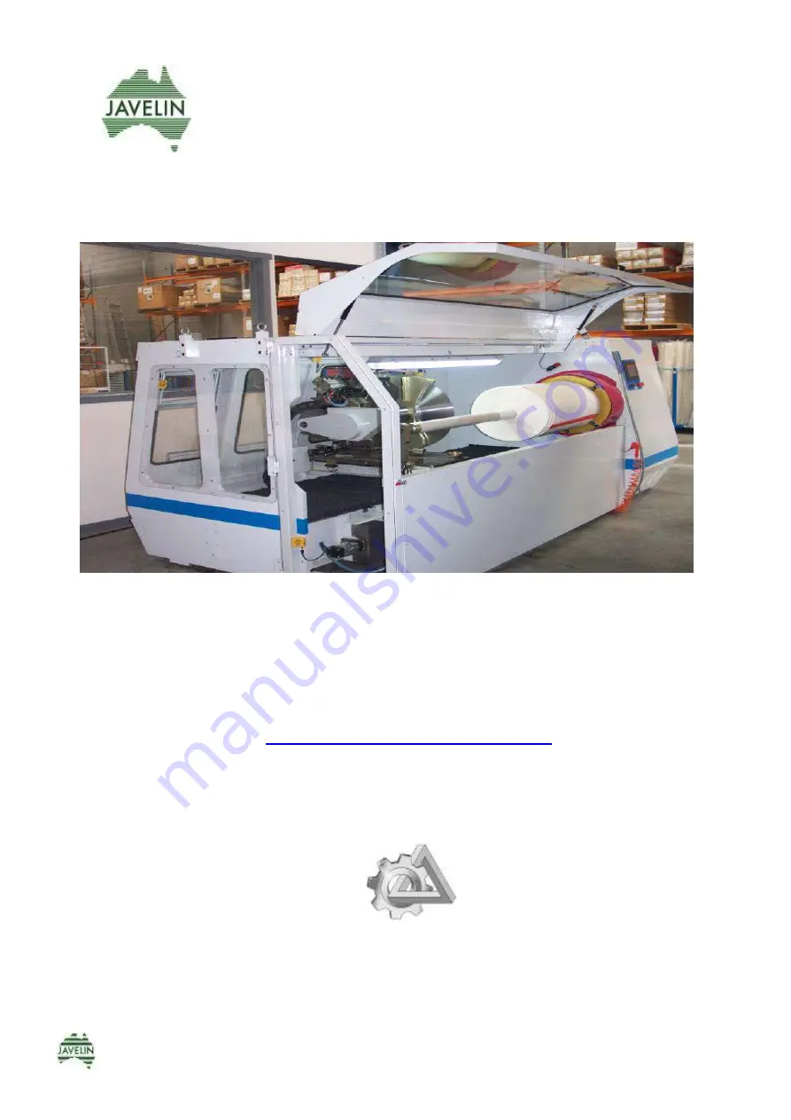
          CN3600


CN3600 Setup & Operation Manual


www.javelinmachinery.com.au


Contents of this manual are © 2020 

Javelin Machinery 

by Industrial Electrical Solutions PTY LTD


18/167 Princes Hwy, Hallam, Victoria, Australia 3803    

Phone 0466 232783


Summary of Contents for CN3600

Page 1: ...___________________________________________ CN3600 Setup Operation Manual Revision 6 2020 1 CN3600 CN3600 Setup Operation Manual www javelinmachinery com au Contents of this manual are 2020 Javelin Machinery by Industrial Electrical Solutions PTY LTD 18 167 Princes Hwy Hallam Victoria Australia 3803 Phone 0466 232783 ...

Page 2: ...nse or have been wound too tightly may be unsuitable to slit by this method Knife parameters are crucial in successful Single Knife Slitting Refer Knife Selection Section 4 8 in Manual In this case either the roll must be rewound to a lesser tension or the material cut on a machine known as a slit rewinder As widths being slit increase so must the secondary or back bevel on the knife in order to b...

Page 3: ..._____________________________________________________________________________________________________________________________________________________________ CN3600 Setup Operation Manual Revision 6 2020 3 ...

Page 4: ...huck Mandrel motor 7 5HP x 4 pole with VS drive Indexing control Ballscrew Servo motor controller Knife forward retract traversing Uses ballscrew Servo motor controller Knife drive 7 5HP x 4 pole with VS drive Automatic knife pivot Angle of knife adjusts 8 degrees using servo motor Knife grinding Automatic knife grinding mechanism Knife coolant Venturi system Electrical control system PLC with aut...

Page 5: ...CHINERY immediately 2 2 LOCATING MACHINE In addition to machine floor plan room should be provided around the machine to allow for Ease of service Loading of material onto mandrel For stacking of raw finished materials See below Fig 2 2 for suggested layout The machine should be located on a relatively flat solid floor that will support a machine weight of approximately 1600kgs Fig 2 2 Space Requi...

Page 6: ...rit level on carriage plate C at right angle to the machine 2 Adjust the two leveling feet D at both ends of the machine so it is level from front to back Step 3 1 Position spirit level on carriage plate parallel E to machine frame and adjust feet so that machine is level from Left to Right 2 Recheck level of machine from front to back NOTE Once machine level supporting feet A should be lowered ju...

Page 7: ... voltage Volts 415 415 Supply Current Amps 26 26 3 phase Earth 4 wire Supply Frequency Hz 50 60 The supply cable for this machine is to be of a size to carry a load of 26 amp The voltage required is 415 volt 3 phase Other voltages can be supplied by a transformer if required A supply connection Fig 2 4 is provided on the terminal strip in the main cabinet The terminals can be located by looking fo...

Page 8: ...rrosion oil contamination and machine malfunction PIPING LAYOUT Fig 2 5a THE FOLLOWING GUIDELINES HAVE BEEN PREPARED TO HELP SOLVE EXISTING AIR PROBLEMS AND TO ALSO HELP SET UP NEW SYSTEMS 1 The best way to get the water out of the air is to cool the air down This is done in the air compressor and air lines 2 Air is never taken from the lowest point the air from main line is taken from the top of ...

Page 9: ...prox 600KPA 90 lb in2 2 Push E to drain water out everyday 3 Check the oil level every week Use Light Hydraulic Oil 4 Lubricator should deliver one drop of oil for every five operations of chuck grip release This can be observed in the sight glass on top of lubricator and adjust by screw F A Pressure setting knob Pull down and turn clockwise direction to increase pressure B Pressure guage C Air so...

Page 10: ...L button and over rides all operation The switch must be pulled outwards before the machine can be started START BUTTON see Fig 3 1B NOTE Keyed Power Switch must be turned ON before Start Button will operate This green illuminated push button is used to restart the system after it has been stopped The green lamp indicates that the system has been started SIDE DOOR OPEN CLOSE Manually operated swit...

Page 11: ... rear stop and carriage left right stop position ENTER PRODUCT SETTINGS Product Setting is used to set the contact and cutting speed as well as the material width and quantity to be slit VIEW PRODUCT PARAMETERS This screen reflects all the settings parameters set ie chuck knife RPM Knife Dwell Time OPERATION Transfers to operation screen to commence slitting SHARPENING Knife Sharpening Manual or A...

Page 12: ...______________________________________________________________________________________________________________________________________________ CN3600 Setup Operation Manual Revision 6 2020 12 3 1 2 CONTROL PANEL SCREENS ...

Page 13: ...____________________________________________________________________________________________________________________________________________________________ CN3600 Setup Operation Manual Revision 6 2020 13 ...

Page 14: ...____________________________________________________________________________________________________________________________________________________________ CN3600 Setup Operation Manual Revision 6 2020 14 ...

Page 15: ...____________________________________________________________________________________________________________________________________________________________ CN3600 Setup Operation Manual Revision 6 2020 15 ...

Page 16: ...____________________________________________________________________________________________________________________________________________________________ CN3600 Setup Operation Manual Revision 6 2020 16 ...

Page 17: ...____________________________________________________________________________________________________________________________________________________________ CN3600 Setup Operation Manual Revision 6 2020 17 ...

Page 18: ...____________________________________________________________________________________________________________________________________________________________ CN3600 Setup Operation Manual Revision 6 2020 18 ...

Page 19: ...____________________________________________________________________________________________________________________________________________________________ CN3600 Setup Operation Manual Revision 6 2020 19 ...

Page 20: ...____________________________________________________________________________________________________________________________________________________________ CN3600 Setup Operation Manual Revision 6 2020 20 ...

Page 21: ...____________________________________________________________________________________________________________________________________________________________ CN3600 Setup Operation Manual Revision 6 2020 21 ...

Page 22: ...he knife spindle should be kept free of any grit and wiped over prior to fitting a knife The spindle is precision ground and supported by two tapered bearings with provision for adjustment 3 2 2 BACKING PLATE WASHER NUT These items must be stored and kept clean in exactly the same manner as for knives see note below Any grit or burrs must be removed or they will cause knife run out and resultant p...

Page 23: ...oviding the knife is always ground in this position as well as being located in this position when slitting you will ensure axial and radial run out of the knife is minimal This is the primary reason for having a knife grinder mounted on the machine Note A rust inhibitor or light oil should be regularly wiped over the knife spindle knife and backing plates to prevent any rust build up 3 2 4 KNIFE ...

Page 24: ... regrind for a minute Stop the grinder and check if all the black mark has been removed This indicates the bevel is correctly ground and right to the edge of the knife 3 3 1 ROUNDING KNIFE EDGE Operator must wear cut proof gloves when performing this function Turn off power at main isolating switch and using a Shielded Oil Stone see Fig 3 3 1 hold the stone flat against knife ege and slowly rotate...

Page 25: ...MANUAL SHARPENING on Sharpening Selector Screen 16 Start Sharpener To start sharpening device and knife rotating Stop Sharpening To stop sharpening device and knife rotating knife grinder assy goes back to zero position Left Sharpen To sharpen the left side of circular knife Right Sharpen To sharpen the right side of circular knife Note The knife speed rpm during the sharpening is set under the sc...

Page 26: ... After No of Cuts To sharpen the left side of knife after number of cuts If set up to 5 it automatically sharpens after every five 5 cuts Left Sharpen Time To set up sharpening time measured in seconds Right Sharpening After Cut To sharpen the right side of knife after number of cuts If set up to 5 it automatically sharpens once after every five 5 cuts Right Sharpen Time To set up sharpening time ...

Page 27: ...ision 6 2020 27 3 4 KNIFE CARRIAGE SETTINGS Fit knife most suitable for tape being slit eg Diameter Cutting Edge Sharp or Rounded 3 4 1 PIVOT POINT ADJUSTMENT Disengage Knife Lock Locate knife pivot point jig onto brass boss on carriage plate Tighten Clamp Bolts Remove Jig Loosen off Knife Pedestal clamp bolts and adjust pedestal so that knife edge just touches the flat on the Pivot Point Jig ...

Page 28: ...o mandrel Scroll through screen s to MACHINE SETTINGS Screen 1 Machine Settings Press KNIFE CARRIAGE SETTINGS Screen 2 Knife Carriage Settings Press screen KNIFE FORWARD STOP Screen 3 Knife Forward Stop Press FAST MOVEMENT then using H H Module move knife forward in High Speed to about 5mm away from mandrel shaft Press screen SLOW MOVEMENT and then bring knife forward by pressing KNIFE FORWARD unt...

Page 29: ...ivated during this set up check the mechanical overtravel stop on the Left Hand side of the carriage There should be approx 1mm clearance To Reset turn keyed power switch OFF and then ON Press START button and repeat procedure for setting forward stop in Screen 3 NOTE If when operating the machine the knife does not quite cut through the core Touch KNIFE FORWARD STOP on screen 7 to display a keypa...

Page 30: ...TOPto go to Screen 4 Knife Adjustable Rear Stop Press FAST MOVEMENT to move Knife forward in High Speed using H H Module to a position where the knife has 10 20 mm clearance from the outside diameter from the log roll Distance dependant on tape thickness Foam and or roll being out of round Press ENTER SETTING on screen 4 Knife will automatically retract to rear position To verify Adj Rear Stop pos...

Page 31: ...ll to Screen 5 Left Right Carriage Stop Load log roll onto mandrel secure Raise mandrel support arm and close guard Press FAST SLOW SPEED Using H Held Module move knife carriage to first cut position Press LEFT STOP ENTER Press FAST SLOW SPEED To verify L H stop position exit Screen 5 move knife carriage right about 50mm and Left again using traverse arrows on H Held Module Carriage should stop at...

Page 32: ...n No OF ROLLS To set the quantity of rolls to be cut Must also be set in Screen 3 WIDTH To set width of rolls to be cut This is also the width distance the knife moves when space forward or space backward is operated CONTACT SPEED The speed the knife moves forward at during the contact distance Normally 3 8 mm sec Normally slower than cut speed CUT SPEED The speed the knife moves forward during th...

Page 33: ... Mode 4 0 Note While setting minus angle you have to enter degree in first and then input symbol Mode 1 is for trimming cut speed slower with larger minus angle Mode 2 is for roll width to be cut small angle for wide width and larger angle for narrow width Mode 3 is for last cut trim on end of log roll cut speed slower with plus angle Note If you want to cut different sizes off one log roll enter ...

Page 34: ...PM to between 150 500 rpm Note Knife is not normally driven when slitting dense tape If it is driven when slitting these tapes keep RPM lower with a high mandrel speed CORE TO MANDREL DISTANCE Usually set to a distance slightly greater than the core thickness 3mm thick core set distance to 4mm NO CUTS REQUIRED Total Total number of cuts required has to be entered Machine counts down to zero The nu...

Page 35: ...h to open side door and release expanding section of mandrel 3 Remove spacer plate from face of chuck 4 Support L Hand end of mandrel and remove the four screws A fixing mandrel flange to chuck 5 Remove mandrel and place on bench Remove the three counter sunk screws and washer at the back of the flange B 6 Mark position of grub screws C in taper lock with marking pen for future reference loosen gr...

Page 36: ...n the SIDE DOOR EXPANDING MANDREL switch is in the ON position The jaws pin holders refer fig 3 9 below can be repositioned in the slide bars by loosening the Grub set screws in the pin holders and sliding the pin holders up or down in the slide bars and retightening the grub set screws Fig 3 9 The gripping diameter can be increased by turning the pin holders around in the slide bars and reversing...

Page 37: ...aring housing B and adjust to correct alignment Tighten screws 4 Move carriage to chuck end of machine and check contact distance of knife to mandrel 3 10 1 2 Horizontal Alignment of Mandrel The mandrel support arm should engage the end of the mandrel with minimal deflection of the mandrel If noticeable deflection is detected lower mandrel support arm and rotate mandrel manually and check for runo...

Page 38: ...section of the mandrel are both controlled by a manually operated switch on the operator control panel 3 11 3 REAR HATCH DOOR SLIDING DOORS As a safety precaution the rear hatch door see Fig 3 11 3 and sliding doors see Fig 3 11 4 are also fitted with safety switches which will shut the machine down when opened NOTE Machine will not operate if guards are opened Note When cleaning the polycarbonate...

Page 39: ... water container see Fig 3 12 We recommend using a product which is as salt free as possible to reduce rust occurring 1 Installation As shown in Fig 3 11 C is the water pipe and D is air pressure pipe Both pipes are 6mm O D The water pipe is connected into water container and then one non return valve is connected E please note the direction of flow The air pressure pipe is connected to a solenoid...

Page 40: ...eservoir see copy manufacturers label below Note The knife pivot ballscrew nut is fitted with a grease nipple and it should be greased monthly Fig 3 13 Auto Lubricator System Lubricator Controls Top Knob controls the lubrication duration This is preset at 10 seconds by the factory and should not be altered Lower Knob controls the frequency of lubrication This is preset at 150min by the factory and...

Page 41: ...rational before starting the machine 3 DO NOT place your hands between the knife and rolls when loading or unloading ENSURE knife is in its furthest back position 4 KEEP the area around the machine CLEAN and DRY Use slip proof surface or mats Only the operator to work within area designated by hazard tape 5 ENSURE main isolator is switched OFF before any maintenance is carried out 6 ALWAYS fit rub...

Page 42: ...e coating tension under which the log has been wound to knife diameter knife sharpness or dullness air or room temperature While Javelin can recommend settings for different products and widths the operator must be aware of the factors mentioned and make adjustments accordingly ALWAYS USE HIGH CHROME HIGH CARBON STEEL KNIVES CHROME CONTENT RETAINS THE KNIFE EDGE DURABILITY WHILE THE CARBON IS FOR ...

Page 43: ...cted TRAV CARRIAGE LEFT TO STOP Carriage will traverse automatically to the left hand stop or until the STOP CARRIAGE TRAVERSING button is pressed STOP CARRIAGE TRAVERSING MANUAL KNIFE FORWARD Knife carriage will move forward to mandrel stop Cut off point and retract to rear adj stop position when button is released Note will only operate when guards are closed START KNIFE AUTO MODE When activated...

Page 44: ... On Disengaged Off Press twice after slitting cycle to activate Start Chuck Mandrel rotation Note Chuck motor will not start If mandrel support arm is down ALL guards must be CLOSED Knife carriage will move forward to cut off point mandrel and retract to rear stop cut position when released Note Will only operate with ALL guards closed Will continue auto mode until roll quantity or right hand forw...

Page 45: ...ide the log roll on without any danger of contact with the knife which can result in serious hand injury H H 16 Lower mandrel support arm H H 17 Fit log roll H H 18 Raise mandrel support arm engage expansion section of mandrel H H 19 Set up knife rear stop Outside Diameter of roll plus 5 20mm for knife clearance 3 4 2 2 20 Move carriage just past left hand end of log roll H H 21 Lower polycarbonat...

Page 46: ...er and can be accessed quickly 1 Level Machine 2 Power Connection 3 Venturi Spray System 4 Machine Lubrication Air Service Unit 5 Backing Support Plates 6 Knife Lock Proximity Switch 7 Set up Knife Pivot Point 8 Fitting Smaller Larger Diameter Knife 9 Carriage Settings Screen 1 10 Set Forward Stop 11 Set Rear Stop 12 Set Left Right Stop 13 Set Product Code Numbers Settings 14 Knife Sharpening 15 C...

Page 47: ...________________________________________________________________________________________________________________________________________ CN3600 Setup Operation Manual Revision 6 2020 47 4 7 TYPICAL SETTINGS PRODUCT PARAMETERS ...

Page 48: ...iner 4 25 4 mm 1 38 mm 1 4 0 40 mm 1 5 8 96mm 4 2 0 Over 100mm 4 THE ABOVE DIMENSIONS ARE A GUIDE ONLY AND WILL VARY ACCORDING TO THE DENSITY OF THE MATERIAL TO BE SLIT Diagram 4 Knife with equal bevel both sides NOTE A rounded edge is preferred for most adhesive tapes Some exceptions would be for example foam sealant tapes w paper liner which require a sharp edge polyimide film is another KNIFE D...

Page 49: ... condition store them in a Javelin knife cabinet or similar Features each drawer has a stop to prevent from falling out centre hole in each drawer makes knives easy to pick up will hold knife diameters up to 450mm 18 Knife cabinet is mobile easy to manoeuvre Operators should read the guidelines for knife selection preparation and maintenance carefully A knife storage box is available for Knife dia...

Page 50: ...nd moisture with clean dry cloth then wipe over with oil impregnated cloth 1 50 50 Kero Oil Remove knife Backing plate washer from machine Clean off all grit and moisture with clean dry cloth then wipe over with oil impregnated cloth 50 50 Kero Oil Knife Carriage Assembly incl Knife Grinding mechanism Mandrel Support Assembly Chuck Face Rack Slides All unpainted surfaces Clean off all grit and moi...

Page 51: ...evision 6 2020 51 5 2 Monthly Maintenance Lubrication Preventative Maintenance Chart Monthly Maintenance Part Method No of Places Lubricant Check Adjust Monthly Lubricate mandrel where it locates into support arm Grease Gun 1 Multi Purpose grease oil Knife Pivot ballscrew nut Grease Gun 1 Multi purpose grease oil NOTE Do not pump excessive amounts of grease into bearing 1 shot is sufficient ...

Page 52: ...ct tension Ball Screw Nut Auto Lubricated 1 Check Auto Lubricate Oil Level Ball Screw Drive Bearing Auto Lubricated 1 Check Auto Lubricate Oil Level Knife Spindle Bearings Sealed Check knife spindle for run out with dial vernier Check knife drive belts for correct tension Machine Level Check machine is level If machine has been moved at any time it must be levelled see manual video Proximity Limit...

Page 53: ... per manual Solonoid valves seals fittings Apply soap and water solution with a brush and check for air leaks and replace where necessary NOTE Do not pump excessive grease into bearings 1 shot is sufficient 5 4 Yearly Maintenance Every 12 months change battery in Servo Controller No HCSFS 52 See date of commencement anniversary date on label above Controller Change battery on this date every year ...

Page 54: ...leeves Speed of knife entry unsuitable Slow down knife entry speed Slit roll telescopes after slitting Log roll wound too tight Rewind log roll to more even tension Inside of cardboard core disintegrates core collapses making tape difficult to remove off Mandrel Lubrication problem Knife edge dull Worn mandrel sleeve Excessive spray on cardboard cores when slitting narrow widths Restrict spray or ...

Page 55: ... product Knife edge must be kept sharp Paper Interliner breaks when slit roll is unwound Too much lubricant spray that is absorbed by paper interliner Cut back on spray Poor quality cut and appearance Knife RPM is too low or too high Experiment with either lower or higher knife speeds Sprays not directed towards edge of knife Centralize spray so it is directed down both sides of the knife Leading ...

Page 56: ...ot allow the knife to overheat An indication of too much heat is the slit roll will have sticky sides In this case lower knife RPM or switch off the knife drive and allow the knife to rotate freely CAUTION With large diameter knives 400mm 16 and above it is recommended you do not set Knife RPM below 80 to avoid overloading knife drive Lubricant Sprays not centralized Angle sprays at the knife beve...

Page 57: ...f open in an anti clockwise direction Non Return valve blocked or stuck closed Clean with airgun Air but no water from nozzle or intermittent spray Water pick up tube not pushed into bottle Water bottle empty Flow valve closed off Loose fitting or split tubes Contaminates in water bottle or spray nozzle Push tube fully home Fill bottle Open an ti clockwise Tighten fitting check tubing Clean bottle...

Page 58: ...ace for burrs or grit iii Fit backing plate and washer and check for runout with dial indicator See Note iv Runout should not be more than 08mm 003 If runout exceeds tolerance mark backing plate in 2 positions and one position on spindle with marking pen v Rotate backing plate to position 2 and re check if runout is excessive 1 2 3 4 backing plate spindle b CHECKING FOR KNIFE RUNOUT Place dial ind...

Page 59: ...No2 Knife Servo CB OL Tripped Reset M1009 No1 sharpen motor OL Reset M1010 No2 Sharpen motor CB OL Reset M1011 Sharpener Time Error M1012 Sharpener Time Error M1013 Sharpener Unlock Error M1015 Knife Pivot Servo OL GLOSSARY Cycle Machine means switch off power at switch on front panel wait 30 seconds and restart if this does not rectify problem switch off power at main isolator switch on electrica...

Page 60: ...k Switches End Switch then OPR M1024 Knife Pivot Servo error Check Limit Switches on rear of carriage M1025 Main doors not closed Check doors and E Stop on Panel M1026 Main doors not closed Check doors and E Stop on Panel M1027 No Air Check Air Pressure M1028 Knife Retract Stop Sensor Fault Check Sensors on Carriage M1029 Knife Retract Deceleration Sensor Fault Call Electrician M1030 Material Thic...

Page 61: ...ned If machine traverses while window is open a M1026 Main Doors Not Closed will occur To recover from this close window cycle machine power If no display on Servo Controller check two pole circuit breaker and cycle machine power If occurs often call Electrician Traverse Servo Controller Displays 9F when battery removed Displays 92 when battery flat I O PLC INPUTS OUTPUTS SAFETY SECTION SERVO CONT...

Page 62: ...nting plate 3 Knife pedestal 5 Sprocket drive motor 7 Support plate knife 10 Bearing housing 12 Sprocket knife spindle 13 Intermediate sprocket 101 Belt 103 Belt 112 Knife lock A Proximity sensor knife lock 3 1 7 112 12 13 101 5 103 IMPORTANT NOTE Before requesting a spare part that is not listed or you are not sure about we suggest you check the item on your machine for any distinguishing numbers...

Page 63: ... Description A Diamond coated grinding wheels B Auto grind cylinder C Grinder mount slide base D Adjusting wheels E Motor Grinder IMPORTANT NOTE Before requesting a spare part that is not listed or you are not sure about we suggest you check the item on your machine for any distinguishing numbers or markings and then email us this information plus a photograph ALSO if possible the entire assembly ...

Page 64: ...02 Pneumatic cylinders qty 2 103 Cylinder mounting foot 110 Screw cap gripping pin 113 Switch for Expanding Mandrel A Pneumatic valve B PE Mandrel Sleeve C Rubber Sleeve Expansion Section D Actuater Pneumatic Valve 110 9 10 101 1 3 A IMPORTANT NOTE Before requesting a spare part that is not listed or you are not sure about we suggest you check the item on your machine for any distinguishing number...

Page 65: ... housing Mandrel 9 Shaft cover Bellows 13 Rear cover bellows 102 Air cylinder 104 Air cylinder 105 Rod end A Flow control B Reed Proximity switch 102 105 104 6 A IMPORTANT NOTE Before requesting a spare part that is not listed or you are not sure about we suggest you check the item on your machine for any distinguishing numbers or markings and then email us this information plus a photograph ALSO ...

Page 66: ... 66 7 5 ADJUSTING SCREW PIVOT POINT No Description 1 Handle 2 Spindle 3 Spindle Housing A JIG PIVOT POINT 2 3 1 A IMPORTANT NOTE Before requesting a spare part that is not listed or you are not sure about we suggest you check the item on your machine for any distinguishing numbers or markings and then email us this information plus a photograph ALSO if possible the entire assembly into which the p...

Page 67: ...7 6 KNIFE CARRIAGE FORWARD RETRACT BALLSCREW DRIVE ASSEMBLY No Description A Servo Motor HC KFS43 B Linear rails A B IMPORTANT NOTE Before requesting a spare part that is not listed or you are not sure about we suggest you check the item on your machine for any distinguishing numbers or markings and then email us this information plus a photograph ALSO if possible the entire assembly into which th...

Page 68: ... housing rhs 3 Ballscrew bearing housing lhs 7 Ballscrew nut A Servo Motor Amplifier Controller located in Electrical Cabinet HC SFS 52 B Servo Motor located in Drive Cabinet HC SFS 52 RHS LHS 1 3 2 1 A IMPORTANT NOTE Before requesting a spare part that is not listed or you are not sure about we suggest you check the item on your machine for any distinguishing numbers or markings and then email us...

Page 69: ...top over travel stop 102 Spray bottle for venture spray 103 Drain bottle overspray 105 Auto lubricator 107 Over travel stop A Drag chain carrying electrical wiring B Expanding rubber bellows 102 2 5 6 5 103 105 102 View from RHS View from LHS A B IMPORTANT NOTE Before requesting a spare part that is not listed or you are not sure about we suggest you check the item on your machine for any distingu...

Page 70: ...scription 1 Ballscrew Nut Mount 4 Ballscrew 5 Ballscrew Nut 8 Motor mount A AC SERVO MOTOR HC KFS13 knife pivot B Limit Switch Zero Position 8 5 1 A IMPORTANT NOTE Before requesting a spare part that is not listed or you are not sure about we suggest you check the item on your machine for any distinguishing numbers or markings and then email us this information plus a photograph ALSO if possible t...

Page 71: ...itch Chuck RPM 5 Servo Motor Traverse HCSFS 52 6 Solonoid Valves mandrel Support 2 Venturi Spray Expanding Mandrel Chuck Knife Grinder 7 Stepdown Transformer 8 Bearing housing chuck spindle 9 Sprocket 10 Sprocket 11 Brake Resistors 1 7 IMPORTANT NOTE Before requesting a spare part that is not listed or you are not sure about we suggest you check the item on your machine for any distinguishing numb...

Page 72: ...ttle for venturi spray 103 Drain bottle overspray 105 Auto lubricator 106 Non Return Valves situated in Spray System Bottle 107 Adjusting Knob for directing spray onto knife 103 105 102 IMPORTANT NOTE Before requesting a spare part that is not listed or you are not sure about we suggest you check the item on your machine for any distinguishing numbers or markings and then email us this information...

Page 73: ...ows D Hatch door access for knife grinding E Handles front safety guard sliding rear doors and hatch window B Gas Struts LHS RHS could have different specifications Check Specs prior to ordering E A D C NOTE ALL GUARDS FITTED WITH CATEGORY 3 INTERLOCK SWITCHES E IMPORTANT NOTE Before requesting a spare part that is not listed or you are not sure about we suggest you check the item on your machine ...

Page 74: ...GE 24 3 3 1 SETTING MANUAL KNIFE SHARPENING 25 3 3 2 SETTING AUTOMATIC KNIFE SHARPENING 26 3 4 KNIFE CARRIAGE SETTINGS 27 3 4 1 PIVOT POINT ADJUSTMENT 27 3 4 2 SETTING KNIFE STOP 28 3 4 2 1 Forward Knife Stop 28 3 4 2 2 Knife Adjustable Rear Stop 30 3 5 KNIFE CARRIAGE TRAVERSING LEFT RIGHT 31 3 5 1 SETTING LEFT RIGHT CARRIAGE STOP 31 3 6 PRODUCT SETTINGS 32 3 6 1 ENTERING PRODUCT SETTINGS 32 3 6 2...

Page 75: ...EMS 54 SLITTING PROBLEMS All Tapes 54 SLITTING PROBLEMS copper aluminium foils 55 SLITTING PROBLEMS single sided closed cell foam sealant tapes 55 SLITTING PROBLEMS soft open cell foam 55 SLITTING PROBLEMS double sided foam mounting tapes 56 6 2 SPRAY SYSTEM 57 6 3 SLITTING TOLERANCES 58 a CHECKING FOR BACKING PLATE RUNOUT 58 b CHECKING FOR KNIFE RUNOUT 58 6 4 FAULT SCREEN ERROR CODES ELECTRICAL P...

Reviews: