

CONNECTION CABLE
INSTRUCTIONS
Thank you for purchasing this Icom product.
The OPC-2389 connection cable is used to connect a
serial communication device to the VE-PG3 or VE-PG4.
READ ALL INSTRUCTIONS
carefully and completely
before using the cable.
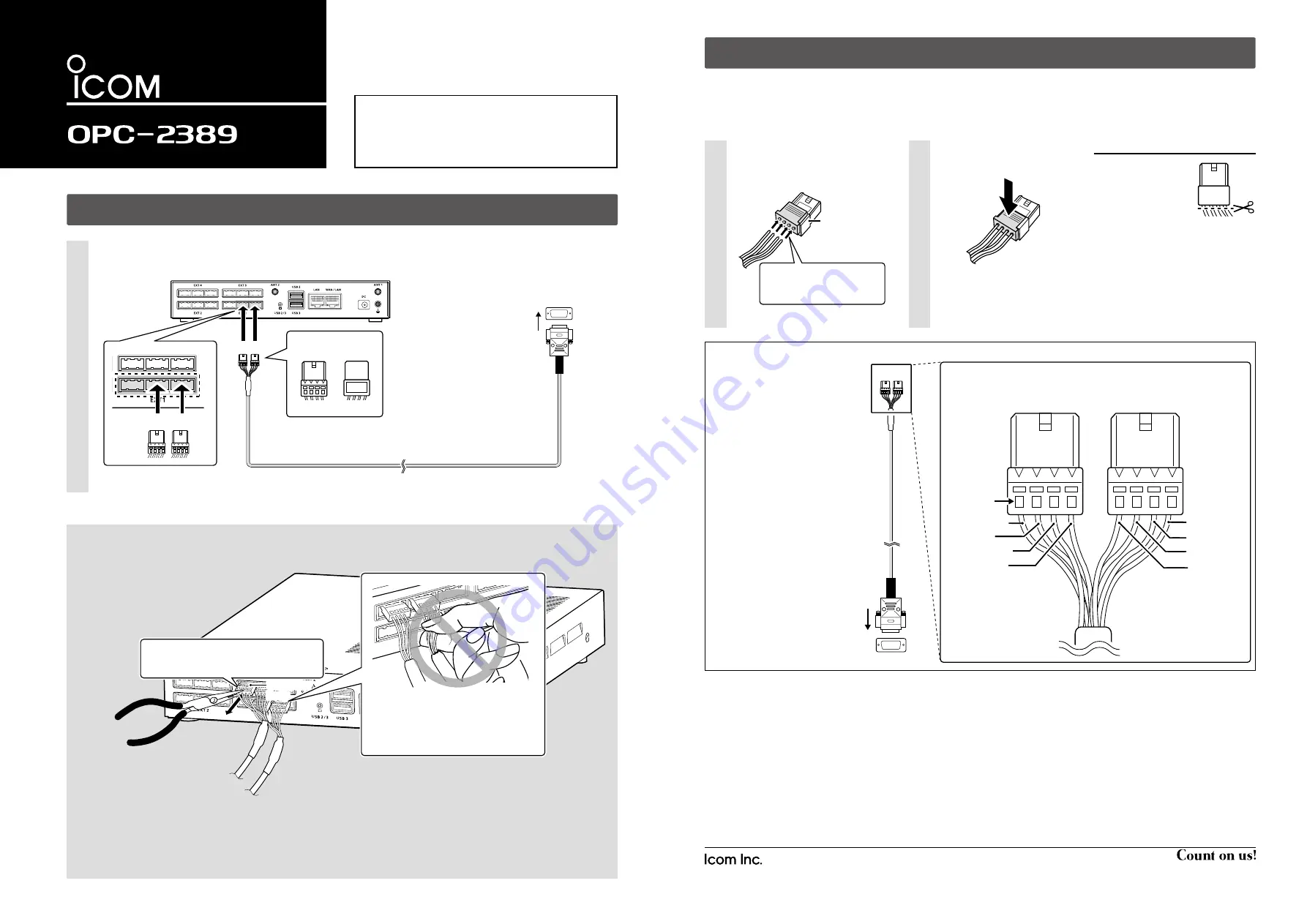
Turn OFF the all devices that are connected to the VE-PG3 or VE-PG4, and then connect the OPC-2389, as shown below.
1
CONNECTING THE OPC-2389
CAUTION
• Verify that both the repeater and the VE-PG3 or VE-PG4 are turned OFF when connecting or disconnecting the cable.
• Hold the connector body when connecting or disconnecting them.
• Never bend or pinch the cable.
• Never place a heavy object on the cable.
• Never touch the cable with wet hands.
• Always connect the cable correctly. An incorrect connection could damage the VE-PG3 or VE-PG4 and/or the connected device.
• Never add a pulling tension to the cable.
• Never use the OPC-2389 with any device other than VE-PG3 and VE-PG4.
Some serial communication devices may not be used.
VE-PG4 (Rear view)
OPC-2389
• This is an example of connecting a serial communication device to the [EXT1] port.
A1
~
A4
A1
~
A4
B1
~
B4
B1
~
B4
C1
~
C4
C1
~
C4
A1
~
A4
A1
~
A4
B1
~
B4
B1
~
B4
C1
~
C4
C1
~
C4
A1
~
A4
A1
~
A4
B1
~
B4
B1
~
B4
C1
~
C4
C1
~
C4
A1
~
A4
A1
~
A4
B1
~
B4
B1
~
B4
C1
~
C4
C1
~
C4
B C
Be sure to insert the
connectors top side up.
Bottom
To a serial communication device
Top
B
1 2 3 4
q
t r e w
y
o i u
B C
When other cables are connected, you can
use needle-nose pliers to carefully insert or
remove connectors.
VE-PG4 (Rear view)
VE-PG4 (Rear view)
Needle-nose pliers
Needle-nose pliers
NEVER pull the connector by holding the
cable. This will damage the cable.
*If the cable becomes damaged, replace
the connector(s). See “REPLACING THE
CONNECTOR” on the reverse side for
replacement details.
Connector
body
Connector
body
REPLACING THE CONNECTOR
If the cable becomes damaged, replace the connector(s). Make wire connections as described below.
• Spare connectors*
1
are supplied with the VE-PG3 or VE-PG4.
*
1
Manufacturer: DDK. Name: 232D-04S1B-DA5-FA
The connector has two parts: a black base and a clear insert.
DO NOT
lock the connector parts before inserting all wires.
Insert the wires into the holes
according to the assigned pin
numbers.
1
Press the clear insert down
until it locks in place.
2
Connector
(Supplied with
the VE-PG3
or VE-PG4)
Connector
(Supplied with
the VE-PG3
or VE-PG4)
The wires for each hole
are assigned by color. See
the illustration below.
OPC-2389
To the serial communication device
B C
q
t r e w
y
o i u
Pin No.
Orange
Orange
Blue
Blue
Yellow
Yellow
Gray
Gray
B
Connector top (Expanded view)
Brown
Brown
Green
Green
Purple
Purple
Red
Red
C
1
2
3
4
1
2
3
4
OPC-2389 connection and wires assignment
RECOMMENDATION
If reconnecting is re-
peated about 30 times,
cut the wires*
2
*
3
near
the connector and re-
place the connector.
*
2
Remove the cable from the VE-PG3 or
VE-PG4, before cutting the wires.
*
3
DO NOT cut the wires too short. Other-
wise it will be difficult to reconnect them
to the VE-PG3 or VE-PG4.
1
2
3
4
• After the insert is locked, it is
impossible to release it again.
Icom, Icom Inc. and the Icom logo are registered trademarks of Icom Incorporated (Japan) in Japan, the United States, the
United Kingdom, Germany, France, Spain, Russia, Australia, New Zealand, and/or other countries.
A7471X-1J-1
Printed in Japan
© 2018 Icom Inc.
1-1-32 Kamiminami, Hirano-ku, Osaka 547-0003, Japan


