


Reviews:
No comments
Related manuals for T1310
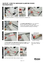
ELITE XT
Brand: Fastbind Pages: 3

HQ Amara
Brand: handi quilter Pages: 2

3704-2/02
Brand: Pfaff Pages: 122

MSK-8220B
Brand: Reliable Pages: 1

NI CVS-1458RT
Brand: National Instruments Pages: 18

TRIDENT T26 SC PLUS
Brand: Hillyard Pages: 28

YP7065
Brand: YARDMAX Pages: 28

H5 Hazer
Brand: Mega Pages: 10

OKIFAX 5750
Brand: Oki Pages: 154

H-Type 969
Brand: DURKOPP ADLER Pages: 90

56416700
Brand: Nilfisk-Advance Pages: 54

VC80LX
Brand: CleanStar Pages: 9

HZL-G Series
Brand: JUKI Pages: 118

Crescendo BLCR
Brand: Baby Lock Pages: 216

HZL-F series
Brand: JUKI Pages: 168

Snack Eenter I
Brand: Crane Pages: 66

The Monsters
Brand: Stern Pinball Pages: 52

KX-TG8321E
Brand: Panasonic Pages: 2


