Hillyard TRIDENT T26 SC PLUS, Use And Maintenance Manual
The Hillyard TRIDENT T26 SC PLUS is a top-of-the-line floor cleaning machine designed for professional use. Ensure optimum performance and longevity with the comprehensive Use and Maintenance Manual. Available for free download at manualshive.com, this manual provides essential instructions and maintenance tips to keep your machine in pristine condition.
Share
Download


Reviews:
No comments
Related manuals for TRIDENT T26 SC PLUS
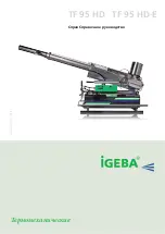
TF 95 HD
Brand: IGEBA Pages: 59
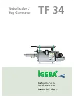
TF 34
Brand: IGEBA Pages: 48

UNO
Brand: Pallmann Pages: 36

Sew Reach ABF Series
Brand: Siruba Pages: 74

7310000
Brand: Clarke Pages: 4

540 - 100
Brand: DURKOPP ADLER Pages: 49

IN 9100
Brand: Insportline Pages: 9

ECO-C Binder 2:1 Pitch
Brand: Officezone Pages: 5

Fax-Lab 220
Brand: Olivetti Pages: 52

BR 90 R
Brand: Kärcher Pages: 15

DDL-8300N
Brand: JUKI Pages: 49

L-1C
Brand: JUKI Pages: 18

J-350QVP
Brand: JUKI Pages: 32

AMS-210EN Series
Brand: JUKI Pages: 249

SC 7900-02 M6 A
Brand: SunStar Pages: 47

LU2-4710-B1T
Brand: Mitsubishi Electric Pages: 28

PLK-J10050RH
Brand: Mitsubishi Electric Pages: 60

LY2-3310-B1T
Brand: Mitsubishi Electric Pages: 20


