JABLOTRON
ALARMS
a.s.
Pod
Skalkou
4567/33
46601
Jablonec
n.
Nisou
Czech
Republic
www
.jablotron.com
||
|
The JA-110ST Bus combined smoke and heat fire detector
The JA-110ST Bus combined smoke and heat fire detector
1 / 2
MLW51605
The JA-110ST is a component of the JABLOTRON JA-100 system.
It is used to detect fire hazards in a building interior. The product is not
designed to be installed in industrial premises. The JA-110ST consists
of an optical smoke detector and a heat detector. The optical smoke
detector is very sensitive to large dust particles which are present in
dense smoke. It is less sensitive to smaller particles generated by the
combustion of liquids such as alcohol. That is why the fire detector also
contains a built-in heat detector which has a slower reaction but is
much better at detecting fire which generates only a small amount of
smoke. The detector has a status reaction (reports its activation and
deactivation). The detector should be installed by a trained technician
with a valid certificate issued by an authorized distributor.
Detector location
The smoke detector must be installed so that any smoke easily drifts
into the detector owing to natural thermal currents (usually on the
ceiling). The detector can only be used in enclosed interiors. It is not
suitable for interiors where smoke can disperse over a large area and
cool down (e.g. interiors with extremely high ceilings – above 5 m) – the
smoke would not reach the detector position.
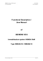
The detector must always be placed in the section leading to the exit
of the building (escape route), see Figure 1. If the building has a floor
area greater than 150 m
2
, installation of an additional detector in some
other suitable place is required, see Fig.2.
1
2
3
4
5
Fig 1
1
2
3
4
5
6
Fig 2
1
2
3
6
Fig 3
1. kitchen,
2. living room,
3. – 6.
bedrooms
y
/
basic
coverage
{
recommended
coverage
It is recommended to place additional detectors in rooms where
people sleep.
Installation on level ceilings
Place the detector in the centre of the room if possible.
The detector
must not be recessed into the ceiling
due to the possible existence
of a cool air layer on the ceiling.
Never place the detector in the
corner of the room
(always keep at least a 0.5 m distance from the
corner) see Fig 4. There is an insufficient circulation of air in corners.
Installation on sloping ceilings
If the ceiling is not suitable for mounting on a level surface (e.g. a
room under a roof ridge), the detector can be installed as in Fig. 5.
0.5m
TOP
Fig 4
0,9 m
Fig 5
centre of the room, best location
acceptable location
Walls, partitions, barriers and lattice ceilings
The JA-110ST detector must not be installed closer than 0.5 m
from any wall or partition.
A narrow space with a width of less than
1.2m requires the detectors to be placed at a distance of at least one
third of its width away. In a case when a room is separated into
sections with furniture, racks or semi partition walls which do not reach
the ceiling, the space is considered to be fully separated if the gap
between the top of these and the ceiling does not exceed 0.3 m.
A free space of at least 0.5m is required under and around the detector.
Any irregularities of the ceiling (e.g. girders) exceeding 5 % of the
ceiling height should be considered a wall and the above-mentioned
limitations should apply.
Ventilation and air circulation
The detectors must not be installed directly by ventilation or air
conditioning vents, etc.
In the case of air being supplied through a
perforated ceiling, each detector must be placed so that no perforation
hole occurs within 0.6 m of the detector.
Avoid installing the detector in the following locations:
places with poor air circulation (niches, corners, apexes of
A-shaped roofs, etc.)
places exposed to dust, cigarette smoke or steam
places with over-intense air circulation (close to ventilators, heat
sources, air conditioning outlets, etc.)
in kitchens and other cooking places (because steam, smoke or
oily fumes can cause false alarms or reduce detector sensitivity).
beside fluorescent lights or energy-saving light bulbs (electrical
interference can cause a false alarm)
in areas with lots of small insects
Warning: Most false alarms are caused by improper
detector location.
See CEN/TS 54-14 standards for detailed installation guidelines.
Installation
When installing the detector, abide by the procedures
recommended in the previous paragraphs.
1
2
3
BUS
1400- 0 0- 0000- 000 1
5
4
6
Fig 6: 1– detector cover opening (removal); 2 – detector cover closing
(insertion); 3 – optical signalling; 4 – arrow showing where to insert the
detector; 5 – bus connection terminals; 6 – production code;
1.
open the detector cover, by turning it anti-clockwise
2. Insert the bus cable
and attach the plastic base
to the selected
place using screws.
3. Connect the bus cable.