JABLOTRON
ALARMS
a.s.
Pod
Skalkou
4567/33
46601
Jablonec
n.
Nisou
Czech
Republic
www
.jablotron.com
||
|
JA-10E BUS keypad
JA-10E BUS keypad
1 / 2
MNX51101
The keypad is a component of the
JA-10
system used to control
the control panel and display its current status. Using an external
input a door detector can be connected to the keypad
.
It is necessary to use this manual in combination with
the JA-10 installation and user manuals.
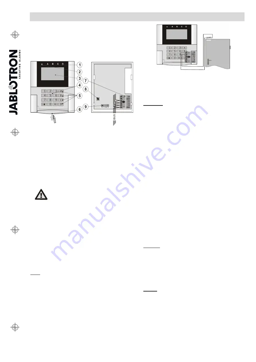
The keypad contains 4 function buttons (5), an LCD display (3),
a system indicator (2), status indicators A, B, C, D (1), a keypad with
an RFID chip card/tag reader (4).
Figure 1 : 1 – status indicators; 2 – system indicator; 3 – LCD display;
4 – keypad and the RFID reader; 5 – function buttons A, B, C, D;
6 – keypad opening tab; 7 – detachable BUS terminals; 8 – tamper
contact; 9 – production number
Installation
1. Open the keypad housing
by pressing the tab on the bottom
(6) using a screwdriver. The tab is also accessible from
the front after opening the keypad cover.
2.
Break away a hole in the plastic base, run the cable through
and screw the plastic back on a selected place. Connect
the cable to the BUS terminals (7). For easier installation you
can detach the BUS terminals, connect the cables and
re-attach them.
3. Insert the keypad back into the plastic base. Make sure
the conductors do not touch the tamper contact spring.
4. Proceed according to the control panel installation manual.
Basic procedure:
a. When the device is switched on, the system indicator (2) will
start flashing yellow repeatedly to indicate that the keypad
has not yet been enrolled to the system.
b. Open the
N-Link
software, select the required position
in the
Devices
window, and click on the
Enroll
button which
will open a
Device information
dialogue window.
c. Click on
Scan/add new BUS devices
which will display a list
of connected unenrolled devices. Double-click on the device
you want to enroll – the JA-10E in this case.
d. The keypad is now enrolled and the yellow LED indicator
switches off.
Notes:
−
The keypad can also by enrolled by opening the enrollment
mode (the Enroll button in the Devices tab of the N-Link SW)
and pressing the keypad’s cover or the tamper contact.
−
Enrollment is also possible by entering its production code (9)
in the N-Link software or using a bar code scanner. All
numbers stated under the bar code must be entered (e.g.
1400-00-0000-0001).
Installation of a magnetic contact
The keypad supports connection of a door detector. The IN input
reacts to being disconnected from the GND contact. The control
panel’s reaction to an activated IN input is configurable in the N-Link
SW.
Figure 2: connecting a magnetic contact
Setting the properties
Go to the
Devices
window in the N-Link software. When you are
at the keypad position, click on the
Internal settings
option which will
display a dialogue window with all properties. Internal settings are
separated into 2 basic tabs:
Function
and
Settings
.
Function tab:
Day and time
– displays the current time in the top-right corner of the
display
The system is not prepared to be Set
– indicates an obstacle
preventing setting the control panel.
User defined text
– enables showing any text, for example the
phone number of an installer company, etc.
Button function
– On the left is a selection of button functions.
On the right is a selection of Sections or PG outputs to which the
functions will be assigned. A function button can be assigned with
these functions: None, Unsetting/setting, Unsetting/Partially setting,
Unsetting/Partially setting/Setting, Section indication, Panic, Fire,
Audible panic, Medical Troubles, PG ON/OFF, PG ON, PG OFF,
PG indication, PG indicates inversely, Common functional button
Authorization
– Setting and Unsetting requires user authorization.
When this parameter is disabled the function buttons can be operated
without authorization, however this does not apply to Unsetting
a section which always requires authorization. Both ON and OFF
statuses of PG outputs can be configured to be operated with or without
authorization
Sections controlled by authorization
– selection of sections which
can be controlled by authorization (using an RFID chip or a code)
PG Control –
selection of PG outputs which can be controlled by
authorization (using an RFID chip or a code)
Logo –
the keypad can display a black and white picture of 128x64
pixels (such as a company logo etc.) which stays on the screen for
25 seconds after the last keypad operation.
Import
– enables copying settings from other keypads of the same
type which have already been enrolled. For example, this can be
utilized when the building has multiple entrances and it is necessary
for all keypads to have identical functions. In addition, this function
can also be used when replacing a faulty keypad with another. The
Import button provides the history of keypad settings on a position of
a particular device.
Setting tab:
Acoustic indication of selected sections:
−
Higher volume
– Increased volume of indication (It does not
apply to alarms).
−
Alarms
– Indicates alarms (sounds a siren).
−
Entrance delay
– continuous sound during the entrance delay
−
Exit delay
– slow beeping (1/sec)
−
Exit delay when partially set
– slow beeping (deactivated
by default)
−
Button status change
–
beeps once when a status is changed
Function:
Optical indication setting:
1.
Indicates permanently
– the keypad indicates permanently.
When the mains electricity is disconnected it indicates
the same way as option 3. When mains electricity is restored
the keypad indicates permanently again.
2.
Section/PG status change on keypad
– The status
change of a section/PG is indicated by a specific function
button and a status indicator. Entrance delay and alarms
are indicated by all function buttons and status indicators.
3.
Section/PG status change on button
– The keypad indicates
after a change of the section/PG status, entrance delay and
alarm only by a particular button and a section indicator.
Always switch the power off before
connecting the keypad to the BUS.