background image

© 2020 Ixom | www.medoraco.com | 866 - 437 - 8076 | [email protected]

O&M_GF10000PW_10499_20200615
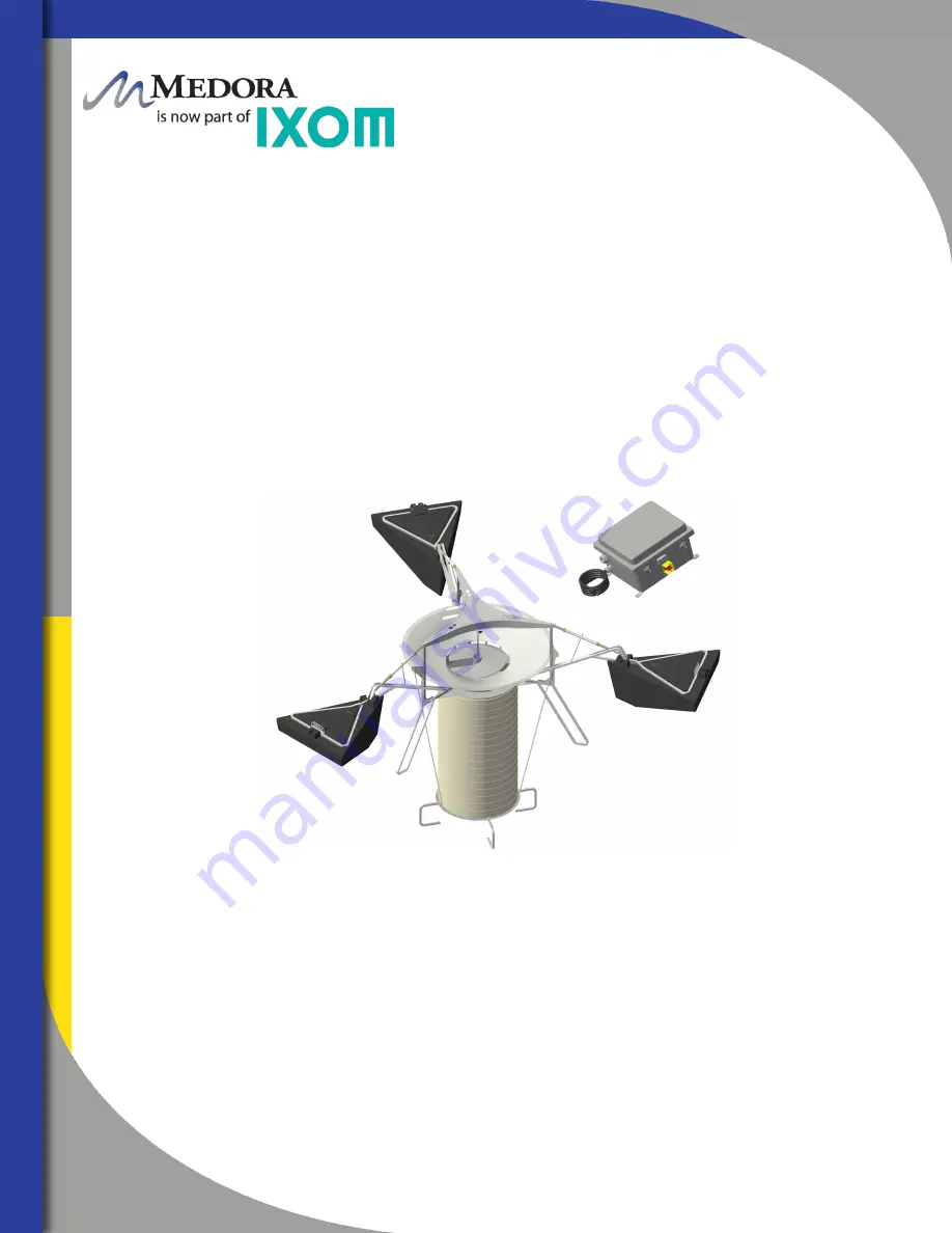
GridBee GF10000PW

Owner's Manual

Summary of Contents for Medora GridBee GF10000PW

Page 1: ... 2020 Ixom www medoraco com 866 437 8076 info medoraco com O M_GF10000PW_10499_20200615 GridBee GF10000PW Owner s Manual ...

Page 2: ...tment Processes Ixom equipment continues to be at the forefront as the 1 world leader for in situ water body treatment 2020 Ixom www medoraco com 866 437 8076 info medoraco com Table of Contents 10014_20200528 GridBee GF10000PW Owner s Manual Safety 1 Operation 4 Site Preparation 5 Features 6 Assembly 14 Maintenance 26 Electrical 33 Technical Specifications 34 Troubleshooting 35 Parts Diagram 38 D...

Page 3: ...ent You can avoid hazards by following these safety instructions and applying some ordinary common sense when operating or servicing this unit Keep in mind that full operator attention and alertness are required when operating or servicing this unit USE COMMON SENSE Most accidents can be avoided by using common sense and concentration on the job being done 2020 Ixom www medoraco com 866 437 8076 i...

Page 4: ...tative ELECTRICAL HAZARD WARNING THIS EQUIPMENT CONTAINS HIGH VOLTAGE ELECTRICAL SHOCK CAN CAUSE SERIOUS OR FATAL INJURY ONLY QUALIFIED PERSONNEL SHOULD ATTEMPT PLACEMENT OPERATION AND MAINTENANCE OF ELECTRICAL EQUIPMENT REMOVE ALL SOURCES OF ELECTRICAL POWER BEFORE PERFORMING ANY SERVICE WORK TO THE MACHINE USE PROPER LOCKOUT TAGOUT LOTO PROCEDURES TO ENSURE A SAFE WORK ENVIRONMENT Rotating Hazar...

Page 5: ...ly with all relative OSHA and local regulations while installing and performing any maintenance to the mixer circulation equipment Key OSHA Compliance Standards that must be followed and not limited to are 1910 146 Permit required confined spaces 1910 147 Lockout Tagout 1926 500 Fall Protection Fall Protection Tips Identify all potential tripping and fall hazards before work starts Look for fall h...

Page 6: ...providing gentle mixing de stratification and surface renewal The GF series GridBee requires a minimal amount of AC grid power The grid provides power to the onboard AC DC power box and motor controller that drive the brushless motor The GF Technology allows the GridBee to operate during day and night while drawing minimal amount of power from the grid During operation a visible flow can be observ...

Page 7: ...l have to follow at a later time once the reservoir is filled with water SANITARY REQUIREMENTS For potable water equipment installations it is very important to maintain sanitary conditions by properly disinfecting all equipment and personnel that come into contact with the reservoir interior and potable water It is recommended that once the hatch is chosen for equipment and personnell entry a cle...

Page 8: ... km hr wind higher than 4 ft 1 2m waves or ice thaw it is possible for the duckbill anchors to pull partly or completely out of the ground or the tether cable span across the pond to break loose from the duckbill anchors If this should happen the pond or reservoir operator will need to re locate the machine to its original position Movement of machine For a GridBee anchored by a tether system the ...

Page 9: ...ller and brushless motor the two components need to be located close to one another This is the primary reason for having the motor controller located directly on the Machine All electronic connections on the Machine equipment should only be used for the inputs or outputs that they are labeled and designed for If any of the leads going into the electronic controller are disconnected be sure when r...

Page 10: ...ft coupling connects the brushless motor drive shaft to the impeller shaft The shaft coupling is located directly below the brushless motor and is made up of 3 main components These components are called the upper coupling lower coupling and coupling sleeve The shaft coupling is designed to allow quick disconnect for removal of the impeller assembly Disconnecting the impeller shaft from the brushl...

Page 11: ...er should freeze around the machine the freeze sleeve will stand still frozen in by the ice but inside the plastic sleeve the impeller shaft will be turning The impeller blades are welded to a hub that is securely fastened to the impeller shaft The impeller is designed to gently pump water from below and can handle up to 4 inch 10cm spherical solids The impeller bushing is a smooth collar that the...

Page 12: ...ing the machine and the upper water layer leaving the dish The top lip of the distributor dish is set from 3 4 inch to 2 5 inches 2 cm to 6 4 cm Please refer to the table below for exact settings below the surface of the water to achieve best flow results The distributor dish depth is set by rotating the turnbuckles located on the float arms Distributor Dish Machine Model Water Level 2500 3 4 in t...

Page 13: ...take draws water horizontally into the hose The contact between the intake and the floor prevents the machine from rotating or moving out of place The machine naturally has a very small torque due to impeller rotation SB2500PW Hose and Intake Box Configuration MODEL MAY VARY SB5000PW GF5000PW SB10000PW GF10000PW 2020 Ixom www medoraco com 866 437 8076 info medoraco com Features Features SB GF PW S...

Page 14: ... without being damaged The turnbuckle is self locking Simply rotate the handle to expand or collapse the turnbuckle for dish depth adjustment It is important to check the distributor dish depth routinely The Machine naturally drops into the water over time due to biomass buildup and trapped air escaping from the hose If the distributor dish lip is too high the water coming off the lip may become t...

Page 15: ...thylene The floats are filled with a Polystyrene closed cell foam for long term buoyancy The floats have a uniquely designed shape to Minimize the interference with the water flow on the surface coming off the distributor dish Have a low profile above the water for minimizing wind resistance and offering less exposure to vandalism Avoid being crushed by ice pressure Provide extra buoyancy when nee...

Page 16: ...ORTANT The following pages give detailed instructions on how to assemble different portions of the machine however the order in which the components are assembled may need to be altered based on the hatch size and whether the reservoir will be dry or empty For instance the hose and intake assembly can be performed on the tank exterior prior to lowering the equipment inside if the hatch size is at ...

Page 17: ... each component will fit through a hatch with clear unobstructed opening of at least 3 feet X 3 feet 0 92m X 0 92m STEP 5 Once these components are lowered through the hatch they can be reassembled using the opposite order of STEPS 1 4 Impeller Reinsertion STEP 1 Place impeller assembly back in place Slide lower coupling into upper coupling and allow to drop down into place Be sure bottom of impel...

Page 18: ...he float up fitting it into the float arm Use the float pins to secure the float to the float arm STEP 5 Place hairpins in each float pin to secure it and prevent the pin from coming out STEP 6 Repeat Steps 1 through 5 for the other two floats NOTE The float plate may not be used on one of the three floats After familiarizing yourself with all the components and gathering the necessary tools you a...

Page 19: ...TO BE PULLED BACK OUT OF THE WATER CORRECTED AND RE INSTALLED SB10000 WITH 15FT 4 5m OR LESS HOSE SB 7500 20FT 4 5m OR LESS HOSE ALL SB5000 ALL SB2500 ALL POTABLE WATER UNITS ALL HIGH SALINITY SALTWATER APPLICATIONS Float Arm to Machine Attachment Assembly 2020 Ixom www medoraco com 866 437 8076 info medoraco com Equipment Assembly 458_10264_20200528 O M_GF10000PW_10499_20200615 17 ...

Page 20: ...STEP 3 Take the float arm and slip the narrow end with Float Arm Stems around the core unit leg Align the holes through the Float Arm Stems with the correct float arm connection hole determined from Step 1 STEP 4 Once aligned slide the M12 X 90mm bolt through all holes Tighten a M12 nylok nut onto the bolt until there is little play or space between the bolted components Use a two 19mm wrenches to...

Page 21: ...of the turnbuckle assembly is in place take the opposite end of the turnbuckle and slide it into the float arm assembly as shown in picture STEP 5 Align the hole through the shaft with the float arm assembly holes and slide the M12 90mm Bolt and tighten the Nylok nut STEP 6 Repeat steps 2 through 5 for each turnbuckle assembly IMPORTANT Hold the center of the turnbuckle assembly and turn both ends...

Page 22: ...ish STEP 3 Place one of the chain brackets over the square tubing with the wider side facing up and the opening facing outward STEP 4 Once the chain bracket is slid around the square tubing insert the M8 x 45mm bolt through the outer holes in the chain bracket Apply anti seize to the threads of the bolt Tighten the M8 nylok nut on the bolt to keep the chain bracket in place using two 13mm wrenches...

Page 23: ... Fasten the leg extension to the machine Core unit assembly using a set of two 5 16 inch x 2 inch 8mm x 51mm clevis pins STEP 5 Secure both pins using two hair pins STEP 6 Repeat steps 2 through 5 for each leg extension NOTE Once the leg extensions are attached and secure the leg extensions act as a tri pod in which the machine can rest on Sliding Leg Extension Around Bottom Leg Of Core Unit Attac...

Page 24: ...se 1 bolt nut for each strainer leg STEP 3 Tighten all 4 bolts nuts using 13mm wrench and socket wrench STEP 4 Tilt or hoist the core unit assembly and slide the hose and intake plate assembly beneath the core unit assembly Line up the upper hose flange slots with the core machine unit flange slots STEP 5 Use M8x20 bolts and M8 nylok nuts to attach the upper hose flange to the core unit assembly f...

Page 25: ...oses together by bolting two flanges using four M8 x 20mm bolts STEP 3 Fasten one end of the hose assembly to bottom of top frame securing the flange to the top frame using four M8 x 20mm bolts STEP 4 Fasten opposite end of the hose assembly to the intake box using four M8 x 20mm bolts STEP 5 Fasten the two intake box tubings using two M8 x 45mm bolts on each tube TOOLS REQUIRED 5 16 Nut Driver fo...

Page 26: ...Injection Hose Assembly 2020 Ixom www medoraco com 866 437 8076 info medoraco com Equipment Assembly 458_10264_20200528 O M_GF10000PW_10499_20200615 24 ...

Page 27: ... Firmly press the two halves together STEP 4 Install the screw clamp around the two coupling halves Tighten the screw clamp while making sure it is seated in the recessed groove which is centered on both coupling havles STEP 5 Once the connection is made neatly route the submersible cable along the machine frame float arm and float where it will not be in contact with sharp edges or moving compone...

Page 28: ...ety comes first every time the Machine is inspected or having maintenance procedures performed It is strongly encouraged that anyone working on or near the machine follow these rules Wear a personal floatation device Stay focused and alert Turn the Machine off before working on it Stay clear of parts while they are moving To turn the Machine motor off turn the On Off switch to the off position To ...

Page 29: ...g a three point rigging system connect to all three rigging points of the Machine Hoist the Machine by the three rigging points and slowly lower into the reservoir STEP 3 Tie as much of the hose up as possible This will reduce some drag when towing the Machine to its position in the reservoir STEP 4 Towing the Machine can be done one of two ways The first way is to hook a chain or towing line arou...

Page 30: ...of a nickel or locating the notch on each chain bracket for machines having a hose If using the notch on each chain bracket the water level should be even with the appropriate notch see picture STEP 3 Set the dish to the correct level in each of the three locations To raise the dish level rotate the turnbuckle around clockwise so that it is expanding To lower the dish level rotate the turnbuckle a...

Page 31: ...l to 1 minute and at least 20 seconds This step is easier with two people one counting revolutions and the other keeping track of the time expired STEP 3 Quit counting revolutions and immediately observe how much time has expired in seconds STEP 4 Use the following equation to calculate rotational speed in rpms Example 30 Revolutions were counted in a time period of 30 seconds RPM 30 revolutions X...

Page 32: ...s first every time the Machine is inspected or having maintenance procedures performed It is strongly encouraged that anyone working on or near the machine follow these rules Wear a personal floatation device Stay focused and alert Turn the Machine off before working on it Stay clear of parts while they are moving To turn the Machine motor off turn the On Off switch to the off position To complete...

Page 33: ... module stand STEP 2 Cover the entire machine including the hose and intake assembly using a heavy duty tarp Be sure to tuck the tarp under the machine to avoid any sand being collected on the machine in the case of sandblasting STEP 3 The electrical cord and chemical injection cord will be suspended from the ceiling so extreme care needs to be taken to prevent damage to the cord and hose from any...

Page 34: ... they do not get tangled on any objects STEP 7 The machine is now ready for the tank to be filled with water and be turned On Most customers feel that removing the machine circulation equipment is the best option for the safety of the equipment Removing the equipment also allows for the contractors to perform their work freely and not have to maneuver around the machine Please contact Ixom Custome...

Page 35: ...ECTRICAL CONNECTION GRID POWER ONLY 120VAC 60HZ 2 0 AMPS MOTOR CONTROLLER BRUSHLESS DC MOTOR 2020 Ixom www medoraco com 866 437 8076 info medoraco com Electrical Electrical Overview GF Series Large Frame Mixers 1927_10299_20200326 O M_GF10000PW_10499_20200615 33 ...

Page 36: ...nt 15 feet 4 5 m of field adjustment with three SS chains connected to hose coupling Self adjusting for all depths up to 40 feet 12 2 m Rotating Assembly Removable assembly with easy access to impeller and impeller shaft Minimum Access Opening Machine Size Weight Machine can be assembled through 3 feet by 3 feet 92 cm by 92 cm clear opening Assembled machine is 16 feet 5 m in diameter and weighs 8...

Page 37: ...ID AC POWER OFF BEFORE ENTERING ENCLOSURE GRIDBEE STRONGLY RECOMMENDS THAT AN ELECTRICIAN INSTALL A BREAKER SWITCH OR OTHER TYPE OF SWITCH THAT WOULD DISCONNECT AC POWER GOING INTO THE ELECTRONIC CONTROL BOX A SWITCH IS NECESSARY TO KILL ALL AC GRID POWER INTO THE ELECTRONIC CONTROL BOX IF THERE BECOMES A NEED TO PERFORM ANY TYPE OF SERVICE INSIDE THE ELECTRONIC CONTROL BOX 2020 Ixom www medoraco ...

Page 38: ...l free to contact a GridBee Customer Service Representative if you experience any problems with your GridBee At GridBee we will get you technical support parts or a service visit to make sure that your GridBee is back online in short time 866 437 8076 or customerservice solarbee com 12 VDC 12 VDC 5 Amp Fuse 45 VDC SUPPLY TO GRIDBEE UNIT 45 VDC Black MOTOR SIGNAL Red MOTOR SIGNAL Green BRAINBOARD T...

Page 39: ...C OFF 45 VDC POWER SUPPLY LED SOLID GREEN LIT SOLID GREEN NOT LIT ERROR CODES 12 VDC ON 12 VDC OFF 12 VDC POWER SUPPLY LED SOLID GREEN LIT SOLID GREEN NOT LIT 12VDC Power Supply LED Brain Board 45VDC Power Supply Under Plate Fuse 5 Amp SD Card Slot Source Power Circuit 120 VAC Control Circuit 12 VDC Motor Power Circuit 45 VDC 5 Amp max Blinking LED s RED YELLOW GREEN Blue Circuit Breaker Brain Boa...

Page 40: ...oat 05 PN 18265000 Turnbuckle Assembly 06 PN 100161 Control Box 07 PN 14013022 Motor Control Cord 08 PN 20014500 14 Brushless Motor 09 PN 26063610 36 x 10 Hose White NSF 10 PN 101284 Leg Extension Kit 01 10 04 09 07 06 03 05 2020 Ixom www medoraco com 866 437 8076 info medoraco com Parts Diagram GF10000PW 1660_10500_20200526 O M_GF10000PW_10499_20200615 38 ...

Page 41: ... 2020 Ixom www medoraco com 866 437 8076 info medoraco com Dimension Drawing GF10000PW 1662_10502_20200526 O M_GF10000PW_10499_20200615 39 ...

Page 42: ... tear If the factory s service crews performed the original on site placement and startup then this warranty also includes labor Where labor is included in lieu of sending a factory service crew to the site for minor repairs Ixom may choose to send the replacement parts to the owner postage paid and may pay the owner a reasonable labor allowance as determined solely by Ixom to install the parts Th...

Page 43: ... and other related subjects as required by OSHA to perform the necessary work to install or remove SolarBee and GridBee equipment and are knowlegeable in the regulations and standards of OSHA If you feel the need to service your SolarBee or GridBee circulation equipment please contact Ixom s Customer Service Department at 1 866 437 8076 Ixom Service Support 2020 Ixom www medoraco com 866 437 8076 ...

Reviews: