iSP M2000, Owner'S Manual
The Yamaha M2000 Operating Manual is an essential companion for users of this exceptional product. With its user-friendly format and comprehensive instructions, this manual ensures a seamless experience. Download the manual for free from our website to explore the full capabilities of the Yamaha M2000.
Share
Download


Reviews:
No comments
Related manuals for M2000
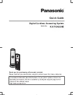
KX-TGK220E
Brand: Panasonic Pages: 16
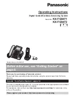
KX-TG9472B
Brand: Panasonic Pages: 64
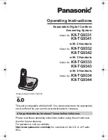
KX-TG9331T
Brand: Panasonic Pages: 60
PB100
Brand: Fellowes Pages: 4

HQ Sweet Sixteen
Brand: Handiquilter Pages: 41

HQ Amara 20
Brand: handi quilter Pages: 2

GARUDAN GF-1107-147 MH
Brand: Anita Pages: 73

149-4
Brand: Singer Pages: 3

JK-1900BSK
Brand: Jack Pages: 42

F-16B
Brand: XPower Pages: 12

SINFONIA GF6
Brand: Necta Pages: 44

FLARE-1000
Brand: Qtx Pages: 6

275 SUPER CUT
Brand: Thomas Pages: 24

KM-757
Brand: SunStar Pages: 35
Argenta
Brand: Azkoyen Pages: 88

FOG-9LED
Brand: FONESTAR Pages: 16

Heavy Duty 1000
Brand: Janome Pages: 72

ULTRAFEED 120931
Brand: Sailrite Pages: 24


