Iso-Tech IDM 91E, Instruction Manual
The Iso-Tech IDM 91E Instruction Manual is an indispensable resource for operating and troubleshooting this innovative product. Available for free download from manualshive.com, this comprehensive manual provides step-by-step instructions and helpful tips, ensuring users maximize the potential of the IDM 91E.
Share
Download


Reviews:
No comments
Related manuals for IDM 91E

mpc2
Brand: MPV Pages: 13

IQBRK3048-2A3
Brand: Snell Pages: 39

FINEST 716
Brand: FINE INSTRUMENTS CORPORATION Pages: 24

ethos 5030
Brand: MTI Pages: 9

DM-50
Brand: Greenlee Pages: 56

SDMM-1
Brand: Greenlee Pages: 44

DM-60 A
Brand: Greenlee Pages: 83
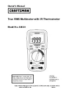
82024
Brand: Craftsman Pages: 13

82315
Brand: Craftsman Pages: 30

82141
Brand: Craftsman Pages: 36

82170
Brand: Craftsman Pages: 17

82139
Brand: Craftsman Pages: 40

82312
Brand: Craftsman Pages: 46

MD-200
Brand: Promax Pages: 58

DMR-1100A
Brand: Circuit-test Pages: 14

81783
Brand: Vorel Pages: 6

DL9308
Brand: Di-LOG Pages: 36

UT531
Brand: UNI-T Pages: 58


