background image

IPU 40108 

  2006  InfraRed  Integrated  Systems  Ltd.  No  part  of  this  publication  may  be  reproduced  without  prior  permission  in  writing  from 

Infrared Integrated  Systems  Ltd.  This document gives  only a  general  description  of  the  products and except where expressly  provided 
shall form no part of any contract. From time to time changes may be made in the products. 


Page 1 of 29 

IRISYS 

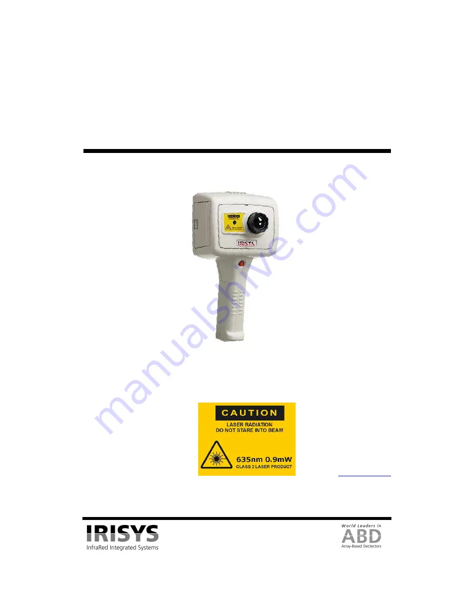
Multi-Purpose Thermal Imager 

IRI 4010 


User Manual 


Safety Warning: 


The equipment described in this document uses a Class 2 laser.  Under no account should anyone look directly into 
the laser beam or the laser beam exit aperture, irreversible damage to the eye may occur.  The laser should not be 
operated when there are personnel in the imager’s field of view. 
 
Caution – use of controls or adjustments or performance of procedures other than those specified in this document 
may result in hazardous laser radiation exposure. 


InfraRed Integrated Systems Ltd 

Park Circle, Tithe Barn Way 

Swan Valley 

Northampton 

NN4 9BG 

Tel: (01604) 594 200 

Fax: (01604) 594 210 

Email: 

[email protected]


Class 2 laser product.  
Complies with IEC/EN 60825-1 
(2001).
 
 
Conforms to USA 21 CFR 1040.10 
and 1040.11 except for deviations 
pursuant to laser notice No. 50 dated 
July 26

th

 2001. 


Summary of Contents for IRI 4010

Page 1: ...no account should anyone look directly into the laser beam or the laser beam exit aperture irreversible damage to the eye may occur The laser should not be operated when there are personnel in the im...

Page 2: ...4 Hot Button 4 Auto Manual 9 3 4 5 Directional Buttons 10 3 4 6 Image Adjustment 10 3 4 6 1 Level and Span Definitions 10 3 4 7 Menu Operation and Functions 11 3 4 7 1 Measurement Settings 11 3 4 7 2...

Page 3: ...ying case you will find the standard items as shown in Figure 1 Figure 1 Contents of the IRI 4010 Multi Purpose Thermal Imager Inspect all the items If any item is damaged or missing please notify you...

Page 4: ...llowing four stages and each stage corresponds to approximately one hour of operation Figure 3 Battery Indicator Levels CAUTION If the IRI 4010 s battery indicator flashes the battery power is running...

Page 5: ...er Supply 3 Operating the IRI 4010 Thermal Imager 3 1 Hardware The IRI 4010 system is designed for use as a handheld thermal imager Thermal images stored on the supplied memory card can be transferred...

Page 6: ...be manually set see Section 3 4 7 4 Figure 7 Splash Screen The IRI 4010 features an On Off power button above the display The IRI 4010 is switched on and off by holding the power button down for more...

Page 7: ...erature measurement values and their temperature difference value Battery life indicator Temperature units C Temperature scale with the maximum and minimum values of the span Four hot button labels If...

Page 8: ...or more information The directional buttons are used to 1 move the position of the measurement cursors 2 adjust the level span brightness and contrast 3 navigate around the menus See Section 3 4 5 for...

Page 9: ...ber See Section 5 3 1 1 4 for how to save an image direct to a PC via the USB cable 3 4 4 3 Hot Button 3 Direction Buttons Control Hot button 3 selects either of the temperature measurement cursors SP...

Page 10: ...e menu is displayed the directional buttons control the movement of the highlighted cursor and adjustment of the highlighted option see Section 3 4 7 Figure 13 Directional Buttons 3 4 6 Image Adjustme...

Page 11: ...available to take you back one menu sub level whilst hot button 4 is always available to exit the menus completely Figure 16 shows an example screenshot from the Measurement Settings menu with the hi...

Page 12: ...our possible colour options They are Rainbow Ironbow Greyscale monochrome or HC Rainbow high contrast Auto Power Turns the imager off if it has been left on without a button press for 20 minutes Facto...

Page 13: ...ge uses and it uses the whole colour bar by default Figure 18 Brightness Contrast Definitions The target thermal brightness and contrast of the auto mode can be manually set when B C is toggled to ON...

Page 14: ...green and yellow in the rainbow example Decreasing the thermal brightness uses more of the lower half See the examples in Figure 18 for more information Figure 19 These 6 figures show the effect of i...

Page 15: ...0108 Page 15 of 29 3 5 Technical 3 5 1 Field Of View The IRI 4010 has a 20 x 15 Field of View and a 160 x 120 19200 pixel detector Figure 20 Field of View Figure 21 19200 Pixel Array 120 pixels 160 pi...

Page 16: ...0 XP PC using the extender USB cable if required 5 Follow the card reader s installation instructions if prompted by Windows 6 Either open My Computer and copy the iri files from the SD card to the PC...

Page 17: ...ult be installed into the following path C Program Files IRISYS IRISYS 4000 Series Imager The above path and name can be changed during the installation but it is advisable to leave it as the default...

Page 18: ...amiliar Windows menu items such as File Edit View Tools and Help Figure 27 The Menu 5 3 1 1 Menus 5 3 1 1 1 File The File menu contains the following features Open Save Save As Revert Excel Output Rec...

Page 19: ...ns window the image the colour bar and the thermal histogram Overlaid on the histogram is the movable span selector which adjusts the level and span of the thermal image The span selector can be moved...

Page 20: ...ure of the application window or the thermal image into the Windows clipboard This picture can then be pasted into a picture editor or Microsoft office document 2 Copy to Bitmap This saves a screen ca...

Page 21: ...ement cursors are added to the image by double clicking in the location that the cursor is required When the mouse cursor is moved over a measurement cursor the mouse cursor appears as a hand When thi...

Page 22: ...mation on the zoom pan control see Figure 40 Figure 36 Area Select 7 8 Isotherms This toggles the two isotherms which can be used to highlight areas of the same temperature in the image A red and or b...

Page 23: ...er independently or by dragging the intersection The short green intensity plot lines on the thermal intensity plots can be moved to analyse temperatures in the plots Double click an intensity plot li...

Page 24: ...hich area of the image to zoom by dragging the green box in the pan control using a mouse The Cursors tab is shown below Figure 41 Cursors Tab In the Cursors tab it is possible to View the temperature...

Page 25: ...gs tab it is possible to Select C F or K Adjust the reflected temperature correction Adjust the target object emissivity Adjust the required capture time and date Add comments to the image The Propert...

Page 26: ...Imager Comms Config to open the window in Figure 44 below Select the USB Serial Port COM X from the list click Test Port and then click OK Figure 44 Port Selection 2 Capture from imager After setting...

Page 27: ...Figure 47 Toolbar 1 Open See Section 5 3 1 1 1 2 Save See Section 5 3 1 1 1 3 Capture from Imager See Section 5 3 1 1 4 4 View Options See Section 5 3 1 1 3 5 Toggle Measurement Cursor list See Secti...

Page 28: ...Corundum 0 850000 Snow 0 850000 Stainless oxidized at 800 C 0 840000 Oxidised Iron at 500 C 0 830000 Cuprous Oxide at 260 C 0 820000 Snow fine particles 0 810000 Brass unoxidised 0 800000 Glass convex...

Page 29: ...of this manual Name Company Name and address Contact Details IRI 4010 Thermal Imager Serial Number This can be found printed under the slots sockets cover PC Software Version installed Software versio...

Reviews: