iCAM IP Address Configuration:
To communicate over an Ethernet based network, the
iCAM requires an IP address to be configured. By default factory settings of an iCAM is set to
the address of 192.168.5.100 with a subnet mask of 255.255.255.0. This IP address can be
changed from the iCAM web configuration screen. For details on viewing/changing an IP
address of an ICAM please refer to the Software Installation Guide.
IP Announcement:
The current iCAM IP address can be determined using the IP announce-
ment function. To activate this function press the right tilt button UP on the front face of the
iCAM. Hold this tilt until the unit face tilts to the UP position and continue to hold for at least
ten seconds. Through the internal iCAM speaker an audible IP will be announced indicating
the current IP address setting programmed in the unit. This function can be enabled or
disabled through the web interface if desired.
iCAM Reset:
The current iCAM contains a reset button located directly to the right of the
positive and negative power connectors. This reset button when depressed for over 3
seconds will reset the iCAM to the factory default settings. Such settings include the IP
address, and web interface login credentials.
iCAM4000 Model Variations
Base RoHS comp. HID iClass IE Smart-ID
Smartcard Reader
iCAM4000
What’s in the box
• iCAM4000 - IrisCamera
• Power Adapter
Input: 110~240V AC - 1.5AMP 50/60Hz
Output: 12V DC - 5.0AMP
• Power Cable for 110V
• CAT5e Ethernet Cable
• Hardware Guide
• Security Screw Wrench
Required Equipment (not included with iCAM4000)
• Server Computer (refer to the software manual for details)
• Ethernet Switch
• Ethernet Wiring
• Uninterruptible Power Supply (strongly recommended)
• The recommended mounting height for the
iCAM4000 is 142cm (56 inches) from the floor to
the bottom of the unit. This mounting height can
be adjusted to accommodate the height of the
average user at the installed location.
• High amounts of ambient light must be avoided.
Intense light sources such as sunlight or halogen
lamps may reduce the image capture performance
of the iCAM, this may result in an increased
“failure to acquire” rate.
• The iCAM is not weatherproof and must not be
exposed to precipitation or extreme temperatures.
An enclosure may be used to protect the unit if
required. See www.lgiris.com – Support & Service
for more information.
• All system components must be powered through
Uninterruptible Power Supplies (UPS). UPS must
provide power line filtering as well as power back-up
operation.
• Each IrisAccess
®
system component if on an Ethernet
network system must have a statically assigned IP
address.
iCAM4000
Hardware Guide
version 1.00
Packing List
Installation Guidelines
The iCAM4000 requires at least the following wires:
• Ethernet network wiring to connect with the network switch to communicate to the Iris-
Server or an ICU.
* Note: For systems consisting of only an IrisServer and iCAM may use an Ethernet cross
over cable to connect the iCAM directly to the IrisServer computer.
• Power (12VDC +/-10% and 2.5Amps MAX)
* Note: If not using the supplied power adapter, use of a stable power supply and proper
gauge wire is required. Wire length voltage drop must be accounted for in order to maintain
the correct 12VDC @ 2.5A power with the iCAM connected. (Ex. 50 feet of 16 gauge copper
wire requires a supply voltage of 13VDC to provide 12VDC power at the iCAM.)
1. When recessed mounting (bracket
optional), leave 6mm (1/4”) of extra
space above the marked hole so
when mounting the back plate it allows
the iCAM to slide down onto the
installation plate tabs. Route the power
line, network line, and other necessary
cables through the back plate hole.
2. Route the power line and other necessary
cables through the back plate hole.
3. Use the appropriate fasteners for the
material in which the iCAM will be
mounted, secure the back plate.
4. Attach the wires from the 12VDC power
supply to the screw terminal connections. The +12VDC (white wire: VCC) power connects
to the + (positive) terminal, whereas the 12VDC ground (black wire: GND) connects to the –
(negative) terminal. Use the appropriate fasteners for the material in which the iCAM will be
mounted, secure the back plate.
5. Connect the CAT5/RJ45 network wire into the LAN port (CN10) of the iCAM. Make sure
that
the RJ45 connector locks securely into the LAN port. (Skip this step if not connecting to
network)
6. Wiegand and/or relay options should be connected at this time. Please see section 5 for
more details.
7. Close front cover and gently slide the iCAM downwards over the back plate. Fasten with
two security screws on the bottom of the unit.
* Note: The iCAM includes two tamper switches. One switch is located on the rear of the
iCAM to detect removal from the wall or enclosure from which it is installed. A second tamper
switch is located behind the front plate to detect tampering with the front of the unit. During
installation be sure that the rear tamper switch is in a position which can detect unit removal
from the wall or enclosure.
Installation
iCAM IP Settings
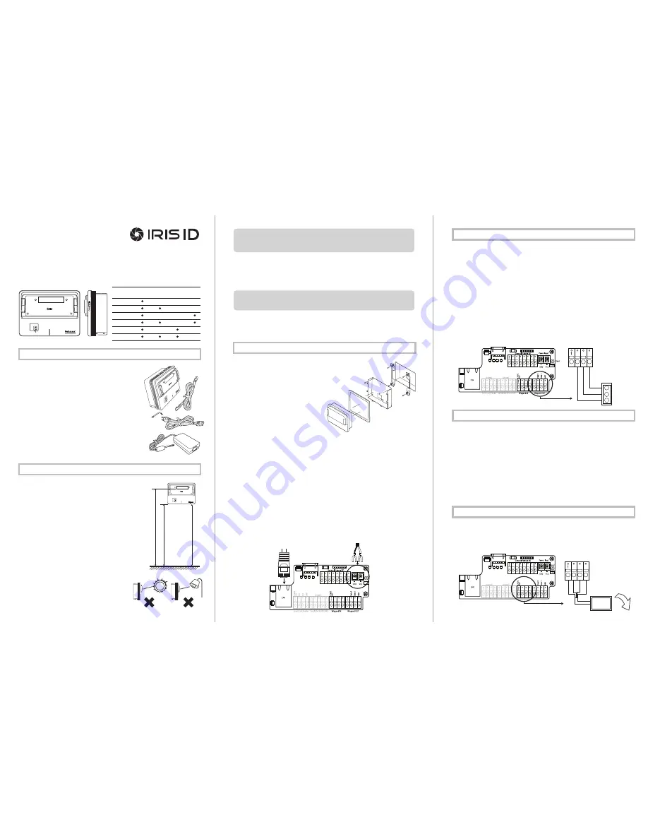
Wiegand Output from iCAM4000:
The Wiegand Output from the iCAM4000 can be used with 3rd party devices capable of receiv
-
ing Wiegand data; this output emulates a typical Access control Card Reader. Configuration
of this output is provided through the iCAM web-interface. See the above image for general
wiring of Wiegand Output to an Access Control Panel.
Wiegand Specifications:
• Wiegand output uses 3 wire interface (Data 1, Data 0, and Ground),
• Maximum wire length from iCAM to Access Control Panel is 500 feet (152m).
*Note: Using IrisAccess EAC software, Wiegand output is available from either the iCAM, ICU
with
WIB board, or a DCU.
Available iCAM Wiegand Output
• A Wiegand input is available on the iCAM for connection from Proximity card readers.
• This connection provides 12-volt DC power that can be used be used to directly power the attach-
ed card reader.
• Configuration of this input is provided through the applicable software application and iCAM web
interface. See image for general wiring of a Prox card reader to an iCAM.
Optional Prox Card
IMPORTANT
:
IT IS RECOMMENDED THAT THE IRISACCESS SYSTEM BE PLACED ON A PRI-
VATE NETWORK SEPARATE FROM GENERAL CORPORATE OR PUBLIC ACCESS. SYSTEM
PERFORMANCE AND STABILITY MAY BE AFFECTED DEPENDING ON AMOUNT OF GENE-
RAL NETWORK TRAFFIC
IMPORTANT
:
IT IS RECOMMENDED TO USE THE POWER ADAPTER SUPPLIED WITH THIS
PRODUCT. AN OVER OR UNDER VOLTAGE APPLIED TO THIS PRODUCT MAY CAUSE PER-
MANENT DAMAGE AND VOID THE WARRANTY.
bottom of
mirror
floor
61”
(155mm)
56”
(142mm)
RECOMMENDED
Power Supply
Connector
Data 0
Data 1
Ground
Access
Control
Panel
Wiegand Out
Reset
Power Input
Ethernet
Cable
iCAM4000R
iCAM4010-E1
iCAM4010R-E1
iCAM4010-H1
iCAM4010R-H1
Power (+12V)
Ground
Data 1
Data 0
Wiegand IN
External
Card Reader