

INSTALLING THE SWITCH TIMER
1. Turn off power at the circuit breaker or fuse and verify that the power is OFF
before wiring.
2. Strip wire ends to 7/16”.
3. Make wire connections using the twist on connectors provided.
4. Remove pull tab from battery tray behind access door. If display does not
appear replace the LR44 batteries.
INSTALLING THE SWITCH TIMER WITH A SINGLE SWITCH SETUP
1. Connect one wire from the wall to the black wire from the switch timer with
the twist connectors provided.
2. Connect the other wire from the wall to the blue wire
from the switch timer with the twist connectors provided.
3.
NOTE:
Cap the RED wire, which is not used in single-
switch installations,with a twist connector.
4. Connect the BARE COPPER wire to the grounding screw
in the box. If a plastic box, connect to ground as supplied.
5. Gently tuck wires into the timer wall box leaving room for the timer.
6. Using screws provided, mount the switch timer into the wall box, then install
the wall plate.
7 Turn the power back on at the service panel.
8. Go to “QUICK SET/INSTALL INSTRUCTIONS.”
INSTALLING THE SWITCH TIMER WITH A 3-WAY SWITCH SETUP
1. Follow above instructions, but wire per diagrams 2 or 3 below.
2. Refer to full instruction sheet for more detailed installation instructions.
QUICK SET/INSTALL INSTRUCTIONS
Please refer to full instruction sheet for more detailed wiring and programming
instructions and troubleshooting.
PROGRAMMING STEPS:
The
MODE
button scrolls through the 6 modes.
CAL
endar,
CLK
(Clock),
PGM (ON/
OFF
Events),
AUTO, AUTO RAND
, and
MAN
ual.
CAL
endar,
CLK
(Clock),
PGM
are settable for your geographic location and schedule
preference.
AUTO, AUTO RAND
and
MAN
are the operating modes.
AUTO
turns On/Off per
the schedule(s) in program.
AUTO RAND
uses the schedule in program but moves
+/- a few minutes each day to give the impression a person is activating the lights.
MAN
allows you turn the light on or off by pushing the timer door, but the program
is not used.
MAN
mode does not erase the program.
The
NEXT ON/OFF
button scrolls through settings in
CAL
and
PGM
modes.
NEXT
ON/OFF
button turns load on or off in operating modes.
The
DAY/DST
,
HOUR+ YEAR-
, and
M+ ZONE+ YEAR+
buttons adjust settings in
CAL, CLK,
and
PGM
modes.
1. CLEAR ALL PREVIOUS SETTINGS
a. Press and hold
NEXT ON/OFF
then press the
RESET
button for 5 seconds and
release both buttons.
b. The timer should be at 12:00 A.M. in
MAN
mode.
2. SET/REVIEW CALENDAR INFORMATION
a. Press
MODE
until
CAL
shows in upper left.
b. Set
YEAR
with
YEAR+
and
YEAR-
buttons.
c. Press
NEXT ON/OFF
to show
dATE
screen.
d. Set date using
M+
(Month) and
DAY/DST
buttons.
DIGITAL ASTRONOMIC TIMER
QUICK SET / INSTALL INSTRUCTIONS
MODEL EJ500 SERIES
Risk of Fire or Electrical Shock
• Risk of injury or death. Remove electrical power at service panel before installing.
• Risk of fire and burns. Do not recharge, disassemble, heat above 212˚F (100˚C),
crush, or incinerate the battery. Keep out of reach of children.
• Do not use timer to control devices that could have dangerous consequences due to
inaccurate timing such as sun lamps, sauna, heaters and crock pots.
• Connect ONLY to wiring rated 90˚C min.
• Follow local electrical codes during installation.
WARNING
- LIMITED ONE YEAR WARRANTY -
For additional programming and detailed warranty information see full
instructions included in box or at: www.intermatic.com
7/16”
BLACK WIRE
BLUE WIRE
RED WIRE
(capped, not connected)
RED WIRE
BLUE WIRE
BLACK WIRE
WIRE FROM
“COMMON” OF
OLD SWITCH
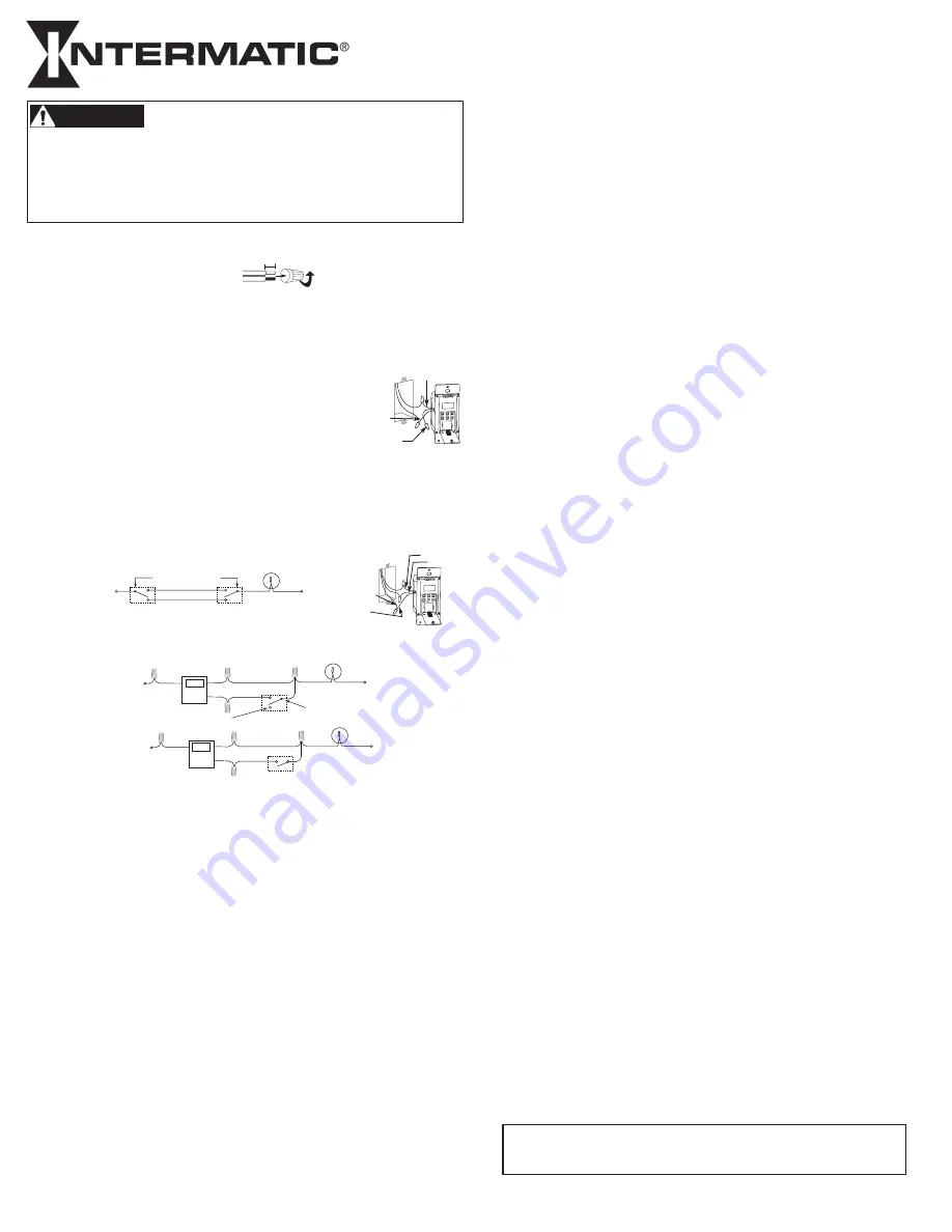
DIAGRAM 1:
TYPICAL
EXISTING
2-SWITCH
SETUP
LOAD
NEUTRAL
3-WAY
MAIN SWITCH
WIRE “A”
“COMMON” TERMINAL
LINE
3-WAY
REMOTE SWITCH
WIRE “B”
WIRE “C”
DIAGRAM 2:
2-SWITCH SETUP,
TIMER INSTALL
RE-USING EXISTING
REMOTE 3-WAY SWITCH
LOAD
NEUTRAL
WIRE “A”
“COMMON” TERMINAL
LINE
3-WAY
REMOTE SWITCH
WIRE “B”
NOT USED
BLACK
TIMER
BLUE
RED
WIRE “C”
JUMPER
DIAGRAM 3:
2-SWITCH SETUP,
TIMER INSTALL USING
NEW SINGLE-POLE
REMOTE SWITCH
LOAD
NEUTRAL
WIRE “A”
LINE
SINGLE-POLE
REMOTE SWITCH
WIRE “B”
BLACK
TIMER
BLUE
RED
WIRE “C”
JUMPER
INTERMATIC INCORPORATED
,
SPRING GROVE, ILLINOIS 60081-9698
http://www.intermatic.com
158--01278
e. Press
NEXT ON/OFF
to show
DST
selection.
AUTO DST
is the default.
f. Use
DAY/DST
button to select
AUTO
for
AUTO
matic
D
aylight
S
aving
T
ime adjust
ment or
MAN
for no adjustment. Arizona & Hawaii should be set to
MAN
.
g. Press
NEXT ON/OFF
to show
ZONE
screen.
h. Select your region
SOUTh, CENTr,
or
NORTh
using
ZONE+
button.
i. Press
NEXT ON/OFF
to show
SNUP
screen.
j. Adjust today’s
SNUP
time using
M+
and
H+
k. Press
NEXT ON/OFF
to show
SNST
screen.
l. Adjust today’s
SUNSET
time using
M+
and
H+
m. Repeatedly press
NEXT ON/OFF
to review your calendar settings.
3. SET/CHANGE TIME OF DAY
a. Press
MODE
button until
CLK
shows on top .
b. Set time of day with
HOUR+
and
M+
buttons.
4. SET SPECIFIC ON or OFF TIMES
Most schedules use 1 program for all seven days.
a. Press
MODE
button until
PGM
shows.
b. Initially Event
“1 ON”
is displayed. Use
NEXT ON/OFF
button to scroll through the
14 possible events, 1-7 ON and 1-7 OFF.
Dashes “ --:--“ means the displayed event has not been set.
c. Starting with event
“1 ON”
, press
DAY
button repeatedly to select a day or
group of days when event
“1 ON”
should operate. After you scroll through all
day choices that also display a time, the time display will be replaced with the
word
“SNST”
, meaning turn
ON
at Sunset (See section 5,
“Set ASTRO Times”
below). Continue scrolling with
DAY
button until the
SNST
display changes back
to a time display, then continue scrolling to select the day or group of days desired
for a specific time for event
“1 ON”
. Scroll to “--:--“ to skip or cancel an event.
d. Set event
“1 ON”
time with
HOUR+
and
M+
.
e. Press NEXT ON/OFF to advance to event “1 OFF”. Follow similar steps as in 4c
and 4d above to set event
“1 OFF”
.
f. Press
NEXT ON/OFF
to display and set additional higher numbered
ON
and/or
OFF
events per steps 4c, 4d, and 4e, above, if needed.
g. When all events scheduled are set, continue to step 7 or 8 below.
5. SET ASTRO EVENTS (AM ON or PM OFF)
“ASTRO”
events occur at the calculated sunset
(ON)
or sunrise
(OFF)
, changing
with seasons.
a. Follow steps in 4c, 4d, and 4e above except use
DAY
button to select
SNST
and
the required days for
ON
events at sunset and to select
SNUP
and the required
days for
OFF
events at sunrise.
b. When all events scheduled are set, continue to step 7 or 8 below.
6. SET SUNSET ON/EVENING OFF EVENTS
a. Follow section 5 to set event
“1 ON”
to
SNST
for desired days.
b. Follow section 4 to set event
“1 OFF”
to a specific late evening time, such as
11:00 PM, making sure to select the same days as used for 6a.
c. Make sure the specific time in 6b is at least 15 minutes later than the latest
summer sunset in your region.
d. When all events scheduled are set, continue to step 7 or 8 below.
7. REVIEW/EDIT SETTINGS:
a. Use
MODE
button to select
CAL
or
PGM
modes.
b. Repeatedly press
NEXT ON/OFF
button to scroll through all settings of each mode.
c. Use
DAY, HOUR+,
and
M+
buttons to edit settings following same steps used to
operating mode per section 8 below.
8. SELECT OPERATING MODE:
AUTO/AUTO RANDOM/ MANUAL
a. Press
MODE
button to select
AUTO, AUTO RAND
om or
MAN
ual operating mode.
AUTO
mode follows the scheduled settings exactly.
AUTO RAND
mode varies the event times slightly each day for a lived-in look.
This applies to fixed and Astro schedules.
MAN
mode maintains but ignores the scheduled settings.
In all operating modes, the load may be turned on or off by pressing the
NEXT
ON/OFF
button , by pressing the closed access door, or by operating the remote
switch in 3-way installations. In the
AUTO
modes, the timer will respond to the next
contrary scheduled
ON
or
OFF
event.
b. Close the hinged access door. Your timer is now ready for use. Press the access
door to turn your load on or off if needed.


