
Thank you for buying the Intel
®
Server System SC5650HCBRP.
The following information will help you assemble your Intel® Server System
SC5650HCBRP and install components.
These guides and other supporting documents are located on the web at
http://support.intel.com/support/motherboards/server/SC5520HC/
If you are not familiar with ESD (Electrostatic Discharge) procedures
used during system integration, please see the Intel® Server
System SC5650HCBRP Service Guide, available on the Intel® Server
Deployment Toolkit CD or at
http://support.intel.com/support/motherboards/server/SC5520HC/.
Please boot to the Intel® Server Deployment Toolkit CD first for BIOS and
firmware configuraion and updates.
Read all cautions and warnings first before starting your server
system integration.
Intel
®
Server System SC5650HCBRP
Quick Start User's Guide
Intel is a registered trademark of Intel Corporation or its
subsidiaries in the United States and other countries.
*Other names and brands may be claimed as the
property of others. Copyright © 2009, Intel Corporation.
All rights reserved.
Warning
Read all caution and safety
statements in this document
before performing any of the
instructions. Also see the
Intel
®
Server Board and Server Chassis
Safety Information
document at:
http://support.intel.com/support/
motherboards/server/sb/cs-010770
.htm
for complete safety information.
Warning
Installation and service of
this product to be performed
only by qualified service
personnel to avoid risk of injury from
electrical shock or energy hazard.
Tools Required
Caution
Observe normal ESD
[Electrostatic Discharge]
procedures during system
integration to avoid possible
damage to server board and/or
other components.
Anti-static
wrist strap
#2 Phillips*
screwdriver
E81444-002
Hex nut driver
(0.25 in or
6 mm)
6
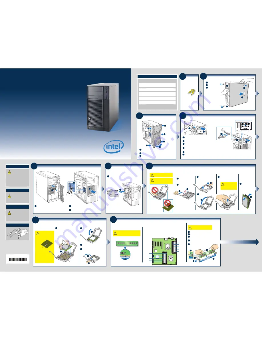
Remove Fan Duct
Remove fan duct assembly as shown.
1
1
2
Remove Side Cover
1
2
Remove two screws.
Push in latch.
3
Slide side cover
rearward and remove.
2
3
1
1
3
Remove Front Bezel Assembly
3
Disengage three bezel clips that attach the right side of the
bezel to the right side of the chassis and remove.
2
Rotate left side of front bezel assembly outward slightly.
1
Lift outward two bezel tabs on left side of bezel assembly to
detach bezel assembly from `the chassis.
2
3
1
1
3
3
1
Preparing
the Chassis
Observe normal ESD
(Electrostatic Discharge)
procedures.
Place your
Intel
®
Server
Chassis on a flat anti-static
surface to perform the following
integration procedures.
Observe ESD procedures before
reaching inside to make
server board connections
or install components.
Minimum Hardware Requirements
To avoid integration difficulties and possible board damage,
your system must meet the following minimum requirements:
•
Processor:
Minimum of one Intel
®
Xeon
®
Processor
5500 Series. Maximum 95-W processor.
•
Memory Type:
Minimum of one 1 GB, 240-pin,
RDIMM or UDIMM, DDR3-800, DDR3-1066, or DDR3-1333.
•
Hard Disk Drives:
SATA/SAS
•
SAS Controller:
One SAS add-in card or SAS module card
•
Heatsink(s):
Minimum of one active heat sink.
For a complete list of compatible
processors, heatsinks,
and memory, see:
http://support.intel.com/support/motherboards/server/S5520HC/
5
Remove Hot Swap Drive Cage
3
2
2
2
Push blue plastic release mechanism upward to
unlatch hard drive cage.
1
Remove Hard Disk Carrier from Hot Swap Drive Cage
and disconnect all cables from the Expander Hot Swap
Drive Cage.
Once released, pull hard drive cage out of chassis.
3
1
4
Install Tool-less CD-ROM or DVD-ROM Drive
1
2
Connect power cables and data cables to rear
of the CD-ROM or DVD-ROM drive.
6
3
5
4
6
Data
Power
3
2
1
Remove EMI shield from 5.25-inch device
drive bay.
Make sure latch is in "unlock" position.
Line up holes in CD-ROM or DVD-ROM
drive with holes in chassis.
Move latch to "lock" position.
Insert CD-ROM or DVD-ROM drive into
device drive bay.
5
4
An additional 4-pin IDE male-to-SATA 15 pin power cable
adapter may be needed if the CD-ROM or DVD-ROM does
not have a 4-pin power connector.
Data cables are included with the Intel
®
Server System.
7a
Install the Processor(s)
A. Open the Socket Lever
Push the lever handle down
and away from the socket to
release it.
Rotate the lever open all
the way.
B. Open the Load Plate
Push the rear tab with your
finger tip to bring the front
end of the load plate
up slightly.
Open the load plate as shown.
A
B
A
B
D. Remove the
Processor
Protective Cover
Take the processor
out of the box and
remove the protective
shipping cover.
A
A
C. Remove Socket
Protective Cover
Save the protective cover.
Grasp the socket protective cover
by the two tabs and carefully lift
straight up as shown.
A
A
B
Cautions:
2. When unpacking a processor,
hold by the edges only to avoid
touching the gold contact wires.
1. When opening a socket, DO NOT
TOUCH the gold socket wires.
B
A
To avoid damage, DO
NOT DROP the cover
onto the socket wires
or components.
7
b
Install the Processor(s) ...
continued
F. Close Load Plate and Socket Lever
Close the
load plate
all the
way as
shown.
Close the socket lever and ensure that
the load plate tab engages under the
socket lever when fully closed.
With your finger, push down on the
load plate as shown.
E. Install the Processor
C
A
B
CAUTION: The underside
of the processor has
components that may damage
the socket wires if installed
improperly.
Processor must align
correctly with the
socket opening
before installation.
DO NOT DROP processor
into the socket!
C
B
A
Components
Orient the processor with the socket
so that the orientation notches on
the processor align with the two
orientation posts on the socket.
A
Install the processor as shown.
A
Orientation Posts
Orientation Notches
8
Install DIMM Memory Modules
To Install DIMMs:
Memory Configurations and Population Order:
The Intel
®
Server System SC5650HCBRP
supports upto 12 DDR3-800/1066/1333
RDIMMs or UDIMMs.
DDR3 DIMM Memory Identification:
DIMM notch and
socket bump must
align as shown.
Open both DIMM socket levers.
Push down firmly on the DIMM until it
snaps into place and both levers close.
Insert DIMM making sure the connector edge
of the DIMM aligns correctly with the slot.
C
A
D
IMPORTANT! Visually check that each
latch is fully closed and correctly
engaged with each DIMM edge slot.
E
Note location of alignment notch.
B
CAUTION: Avoid touching contacts
when handling or installing DIMMs.
E
DDR3
A
C
D
B
•
M
inimum of one 1 GB DDR3-800/1066/1333 RDIMM or UDIMM.
•
Install from first slot of each channel (A1, B1, C1, D1, E1, or F1).
•
Install Quad-Rank DIMM from first slot of each channel.
•
Channel D, E, and F are not available when CPU 2 socket is empty.
•
Mixing of RDIMMs and UDIMMs is not supported.
CPU 1 Socket
CPU 2 Socket
DIMM A2
DIMM A1
DIMM B2
DIMM B1
DIMM C2
DIMM C1
DIMM D2
DIMM D1
DIMM E2
DIMM E1
DIMM F2
DIMM F1
Go to Side 2


