background image

SAFETY WARNING

Only qualified personnel should install and service the equipment. The installation, starting up, and servicing 
of heating, ventilating, and air-conditioning equipment can be hazardous and requires specific knowledge and 
training. Improperly installed, adjusted or altered equipment by an unqualified person could result in death or 
serious injury. When working on the equipment, observe all precautions in the literature and on the tags, 
stickers, and labels that are attached to the equipment.

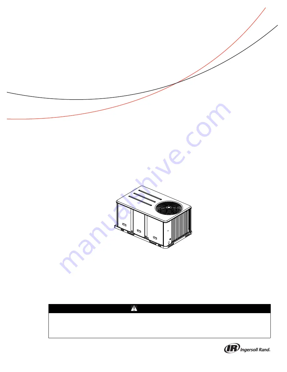
Packaged Rooftop Air Conditioners
Precedent™ — Heat Pump

3 to 10 Tons — 60 Hz

Installation, Operation, 
and Maintenance

Model Numbers

WSC036H-WSC060H
WSC072H, WSC090E, WSC102H & WSC120H
W/DHC036H-W/DHC060H

RT-SVX23M-EN

April 2018

Summary of Contents for Precedent WSC072E

Page 1: ...led adjusted or altered equipment by an unqualified person could result in death or serious injury When working on the equipment observe all precautions in the literature and on the tags stickers and labels that are attached to the equipment Packaged Rooftop Air Conditioners Precedent Heat Pump 3 to 10 Tons 60 Hz Installation Operation and Maintenance Model Numbers WSC036H WSC060H WSC072H WSC090E ...

Page 2: ...ation which if not avoided could result in minor or moderate injury It could also be used to alert against unsafe practices NOTICE Indicates a situation that could result in equipment or property damage only accidents WARNING Proper Field Wiring and Grounding Required Failure to follow code could result in death or serious injury All field wiring MUST be performed by qualified personnel Improperly...

Page 3: ...demarks of their respective owners Revision History Updated to include new WSC102H WSC120H WARNING Follow EHS Policies Failure to follow instructions below could result in death or serious injury All Ingersoll Rand personnel must follow Ingersoll Rand Environmental Health and Safety EHS policies when performing work such as hot work electrical fall protection lockout tagout refrigerant handling et...

Page 4: ... Heat 27 Electric Heat Requirements 28 Low Voltage Wiring AC DC Requirements 28 Condensate Drain Configuration 28 Filter Installation 29 Field Installed Power Wiring 29 Standard Wiring 29 Optional TBUE Wiring Through the Base Electrical Option 29 Field Installed Control Wiring 30 Controls Using 24 VAC 30 Controls Using DC Analog Input Outputs Standard Low Voltage Multiconductor Wire 30 Space Tempe...

Page 5: ...pt for 10 Ton Units 50 Return Air Smoke Detector 51 Economizer Start Up 51 Compressor Start Up 52 Heating Start Up 52 Final System Setup 53 Maintenance 54 Fan Belt Adjustment Belt Drive Units 54 Monthly Maintenance 55 Filters 55 Return Air Smoke Detector Maintenance 55 Condensate Overflow Switch 55 Cooling Season 55 Heating Season 55 Coil Cleaning 56 Troubleshooting 58 ReliaTel Control 58 System S...

Page 6: ...Standard Panels Standard Filters A Hinged Access Panels Standard Filters B Standard Panels 2 MERV 8 Filters C Hinged Access Panels 2 MERV 8 Filters D Standard Panels 2 MERV 13 Filters E Hinged Access Panels 2 MERV 13 Filters Digit 17 Condenser Coil Protection 0 Standard Coil 1 Standard Coil with Hail Guard 2 Black Epoxy Pre Coated Condenser Coil 3 Black Epoxy Pre Coated Condenser Coil with Hail Gu...

Page 7: ...relief for horizontal configuration Barometric relief for horizontal configured units must be ordered as field installed accessory 5 Through the base electric required when ordering disconnect circuit breaker options 6 Requires use of disconnect or circuit breaker 7 Standard metering devices are TXVs 8 The return air smoke detector may notfit upor workproperly on the Precedent units when used in c...

Page 8: ...s the unit model number serial number electrical characteristics refrigerant charge as well as other pertinent unit data Compressor Nameplate The nameplate for the compressors are located on the side of the compressor Unit Description Before shipment each unit is leak tested dehydrated charged with refrigerant and compressor oil and run tested for proper control operation The condenser coils are a...

Page 9: ...RTOM A diagnostic SERVICE signal is sent to the remote panel if the pressure differential across the filters is at least 0 5 w c The contacts will automatically open when the pressure differential across the filters decreases to approximately 0 4 w c The clogged filter output is energized when the supply fan is operating and the clogged filter switch has been closed for at least 2 minutes The syst...

Page 10: ...clock and day may have to be reset The zone sensor allows selection of 2 3 or 4 system modes Heat Cool Auto and Off two fan modes On and Auto It has dual temperature selection with programmable start time capability The occupied cooling set point ranges between 45 and 98 degrees Fahrenheit The heating set point ranges between 43 and 96 degrees Fahrenheit A liquid crystal display LCD displays zone ...

Page 11: ...Airflow through the unit is affected by the amount of dirt and debris accumulated on the indoor coil and filters To insure that airflow through the unit is adequate for proper sampling by the return air smoke detector complete adherence to the maintenance procedures including recommended intervals between filter changes and coil cleaning is required Periodic checks and maintenance procedures must ...

Page 12: ...e dust If symptoms persist seek medical attention Skin Contact Wash affected areas gently with soap and warm water after handling WARNING Fiberglass Wool Exposition to glass wool fibers without all necessary PPE equipment could result in cancer respiratory skin or eye irritation which could result in death or serious injury Disturbing the insulation in this product during installation maintenance ...

Page 13: ...RT SVX23M EN 13 Dimensions and Weights Figure 1 Typical installation clearances for single multiple unit applications WSC036 048H W DHC036H Units WSC060 120E H W DHC048 060H Units ...

Page 14: ...t lift unit approximately 24 inches to verify proper center of gravity lift point To avoid dropping of unit reposition lifting point if unit is not level Table 1 Maximum unit corner weights lbs and center of gravity dimensions in Unit Maximum Model Weights a Corner Weights b Center of Gravity in Tons Model No Shipping Net A B C D Length Width 3 WSC036H 612 507 144 122 110 130 32 21 4 WSC048H 645 5...

Page 15: ...to W DHC 460 575V units 29 29 Barometric Relief 7 10 10 10 Coil Guards 12 20 20 30 Economizer 26 36 36 36 Electric Heaters d d Applicable to heat pump units only W C 15 30 30 40 Hinged Doors 11 12 12 12 Low Leak Economizer 68 93 93 93 Manual Outside Air Damper 16 26 26 26 Motorized Outside Air Damper 20 30 30 30 Oversized Motor 8 8 8 Powered Convenience Outlet 38 38 38 50 Powered Exhaust 40 80 80 ...

Page 16: ...1 MM 6 1 2 165 MM 3 11 16 94 MM 4 7 8 124 MM 5 1 16 128 MM 9 15 16 253 MM SUPPLY RETURN 3 4 14 NPT DRAIN CONNECTION CONDENSER COIL 17 1 4 438 MM 8 7 8 225 MM 13 1 4 337 MM 23 1 4 591 MM 3 3 16 81 MM 14 3 4 375 MM 4 3 4 121 MM Figure 6 Heat pump 3 to 4 tons standard efficiency 3 ton high efficiency unit clearance and roof opening Figure 7 Heat pump 3 to 4 tons standard efficiency 3 ton high efficie...

Page 17: ...ton high efficiency downflow airflow supply return through the base utilities 17 7 8 454 MM 16 406 MM 22 1 4 565 MM Applicable to Y_C models only EVAPORATOR SECTION ACCESS PANEL ALTERNATE CONDENSATE DRAIN CONNECTION 3 4 14 NPT DIA HOLE 4 1 4 108 MM 27 5 8 701 MM 47 7 8 1216 MM 88 5 8 2251 MM 18 1 2 470 MM 9 5 8 244 MM 5 5 8 143 MM 1 2 NPT GAS CONNECTION 60 MBh 80 MBh 100 MBh 120 MBh 130 MBh not ap...

Page 18: ... 51 MM 83 7 8 2130 MM 80 1 2 2045 MM 18 1 2 470 MM 1 25 MM 6 5 8 168 MM 18 1 4 470 MM 1 25 MM RETURN SUPPLY Figure 17 Heat pumps 5 to 10 tons standard efficiency 4 to 5 ton high efficiency downflow duct connections field fabricated Note Reference tabular information for duct clearance to combustible materials in the Installation chapter Figure 18 Heat pumps 5 to 10 tons standard efficiency 4 to 5 ...

Page 19: ... 71 MM 51 3 16 51 3 16 1316 MM 1316 MM 4 1 8 4 1 8 104 MM 104 MM Figure 23 Heat pump 10 tons high efficiency Note 2 Electrical Connection Single Point Power When Heat Installed Figure 24 Heat pump 10 tons high efficiency unit clearance and roof opening Figure 25 Heat pump 10 tons high efficiency roof curb Note 2 Electrical Connection Single Point Power When Heat Installed UNIT CONTROL WIRE 7 8 22 ...

Page 20: ...he unit provide a water tight flexible connector at the unit to prevent operating sounds from transmitting through the ductwork All outdoor ductwork between the unit and the structure should be weather proofed after installation is completed WARNING Risk of Roof Collapsing Failure to ensure proper structural roof support could cause the roof to collapse which could result in death or serious injur...

Page 21: ...he curb instruction booklet Curb ductwork must be fabricated and installed by the installing contractor before the unit is set into place Note For sound consideration cut only the holes in the roof deck for the ductwork penetrations Do not cut out the entire roof deck within the curb perimeter Figure 29 Heat pumps 5 to 10 tons standard efficiency 4 to 5 ton high efficiency downflow airflow supply ...

Page 22: ...lift the unit to ensure it is properly rigged and balanced make any necessary rigging adjustments Figure 32 View for base to roof curb alignment WSC120E W DHC120H on 60 x 84 roof curb Model Number Clearance required from duct to combustible surfaces inches WSC036H 0 WSC048H 0 WSC060H 0 WSC072E H 1 WSC090E H 1 WSC092H 1 WSC102H 1 WSC120E H 1 WHC036H 0 WHC048H 0 WHC060H 0 WARNING Heavy Objects Failu...

Page 23: ...hout buckles or cracks Install and connect a condensate drain line to the evaporator drain connection Note Condensate Overflow Switch if equipped will not work if unit is not level or slightly sloped toward switch Factory Installed Economizer Ensure the economizer has been pulled out into the operating position Refer to the economizer installers guide for proper position and setup Install all acce...

Page 24: ...izontal discharge the following conversion must be performed 1 Remove RETURN and SUPPLY duct covers 2 Place SUPPLY DUCT COVER over downflow return opening insulation side down 3 Using self drilling screws or screws removed from duct cover screw through dimples to attach Duct Cover to base 4 On original RETURN DUCT COVER apply 6mm continuous bead of 500 F RTV sealant around flange opposite insulati...

Page 25: ...ecured by a wire tie near the electric heater terminal block in the heater compartment Attach it to the heater element mountingplatewiththetwo screwsthatwere removed in step 2 above Connect the two wires that were un hooked in step 2 to the terminals on the new TCO A Refer to the heater package wiring diagram to assure that the wiring is connected properly 4 Close the electric heater dead front pa...

Page 26: ...p 2 secure the bottom bracket Note Refer to horizontal view below Air Fi Wireless Communication Interface The factory installed wireless communications interface is installed in the downflow discharge position If a unit is to be converted to horizontal discharge the following conversion must be performed 1 If the unit has an economizer it must be pulled out in the operating position 2 Remove the s...

Page 27: ...st be isolated during field gas piping test that exceed 1 2 PSIG It is recommended that the field piping be capped prior to the unit gas train or optional through the base gas shut off valve if present Gas supply line properly sized and connected to the unit gas train All gas piping joints properly sealed Gas piping leak checked with a soap solution If piping connections to the unit are complete d...

Page 28: ...ss panel and supply air access panels 2 Remove the support panel that the condensate drain pan exits through 3 Slide the condensate drain pan out of the unit 4 Place on a level surface in the position it was removed from the unit 5 Remove the plug knockout in the bottom of the drain pan to convert it to through the base drainage 6 Plug the original condensate drain opening with a field supplied 3 ...

Page 29: ...nit for specific termination points 2 Provide proper grounding for the unit in accordance with local and national codes Optional TBUE Wiring Through the Base Electrical Option 1 Location of the applicable electrical service is illustrated below Refer to the customer connection diagram that is shipped with the unit for specific termination points The termination points depending on the customer opt...

Page 30: ... the unit and components utilizing a DC analog input output signal refer to the Dimensional information in the Dimension and Weights chapter for the electrical access locations provided on the unit 1 The zone sensor module wiring table lists the conductor sizing guidelines that must be followed Figure 48 WSC120E W DHC120H WARNING Proper Field Wiring and Grounding Required Failure to follow code co...

Page 31: ...ductor for the length of the run 3 Do not run the electrical wires transporting DC signals in or around conduit housing high voltage wires 4 Route low voltage wiring per Figure 51 p 32 Table 5 Zone sensor module wiring Distance from Unit to Control Recommended Wire Size 0 150 feet 0 45 7 m 22 gauge 33 mm2 151 240 feet 46 73 1 m 20 gauge 50 mm2 241 385 feet 73 5 117 3 m 18 gauge 75 mm2 386 610 feet...

Page 32: ... WIRING ROUTE FIELD WIRING AS SHOWN AND SECURE WITH 2 WIRE TIES REFRIGERATION MODULE COMMUNICATION INTERFACE LTB ReliaTel TBU WIRING ROUTE FIELD WIRING AS SHOWN AND SECURE WITH 3 WIRE TIES TBU OPTION UNPOWERED CONVENIENCE OUTLET SECURE FIELD INSTALLED WIRING FOR CONVENIENCE OUTLET WITH POP IN WIRE TIE Figure 52 ReliaTel without TBUE control customer wire routing W DHC120H ...

Page 33: ... illustrates two series circuits with two sensors in each circuit wired in parallel The square of any number of remote sensors is required Example 2 illustratesthreesensorssquaredinaseries parallelcircuit Using BAYSENS077 two sensors are required to accomplish space temperature averaging Example 3 illustrates the circuit required for this sensor The following table lists the temperature versus res...

Page 34: ...n numbers are for reference only There are multiple smoke detector systems that could have differently numbered pins For correct wiring details please refer to the specific smoke detector literature that accompanied this unit Figure 54 Examples ...

Page 35: ...T SVX23M EN 35 Figure 55 Typical field wiring diagrams for optional controls BA YSENS075 BA YSENS075 BA YSENS119 BA YSENS110 BA YSENS108 BA YSENS106 BAYSENS073 BAYSENS074 BAYSENS075 ASYSTAT669A OPTIONAL REMOTE SENSOR ...

Page 36: ...5 824 K Ohms Table 7 Sizing natural gas pipe mains and branches Iron Pipe Size IPS Inches Length of Pipe Ft Pipe Pipe 1 Pipe 1 Pipe 1 Pipe 15 76 176 345 750 1220 30 52 120 241 535 850 45 43 99 199 435 700 60 38 86 173 380 610 75 77 155 345 545 Note Capacity of Pipe of Different Diameters and Lengths in Cu Ft Per Hr with Pressure Drop of 0 3 and Specific Gravity of 0 60 Table 8 Iron pipe size SI mi...

Page 37: ... farthest from average 221 The percentage of Imbalance equals The 2 2 imbalance in this example exceeds the maximum allowable imbalance of 2 0 This much imbalance between phases can equal as much as a 20 current imbalance with a resulting increase in motor winding temperatures that will decrease motor life If the voltage imbalance is over 2 notify the proper agencies to correct the voltage problem...

Page 38: ...compressor mechanical failures Before starting the unit in the Cooling mode set the system switch to the Off position and turn the main power disconnect to the On position and allow the crankcase heater to operate a minimum of 8 hours Before closing the main power disconnect switch insure that the System selection switch is in the Off position and the Fan selection switch is in the Auto position C...

Page 39: ...s Multi Speed Fan Output 1 Fan On Minimum Position Setpoint 0 Off Off Off Off 2 2K Low Minimum Ventilation On Selectable Off Off Off Off 2 Economizer Test Open On Open Off Off Off Off 3 3K Low 3 Cool Stage 1 On Minimum Position On b Off Off Off 4 7K Low 4 c Cool Stage 2 On Minimum Position On b On Off Off 6 8K High 2 step cooling Low 2 step cooling 5 c Reheat On Minimum On On Off Off 33K High 6 c ...

Page 40: ...ectric heat On or gas heat Off Table 12 Heat Pump with Multi Zone VAV Fan Control Test Step Mode C1 C2 CFA CFB Heat 1 Heat 2 SOV1 Econ a S Fan CV Fan Speed Command 1 IGV VFD Open Off Off Off Off Off Off Off Closed Off Min Speed 2 IGV VFD Closed Off Off Off Off Off Off Off Closed Off Min Speed 3 Fan On Min Vent Off Off Off Off Off Off Off Min On Min Speed 4 Econ Off Off Off Off Off Off On 100 On In...

Page 41: ...he low pressure control LPC2 high pressure control HPC2 and discharge line thermostat TDL 2 are closed When the CC2 contacts close compressor CPR2 starts to maintainthe zonetemperature to within 2ºF of thesensor setpoint at the sensed location Three Stages of Cooling Note High efficiency units only When the unit is configured for three stage cooling and the system switch is set to the cool positio...

Page 42: ...t cycle has terminated and the compressor Off time delay has been satisfied Note Units with the dehumidification option When in dehumidification mode the unit will not cycle as described above The unit will run continuously in dehumidification mode at all ambient conditions above 40ºF Dehumidification is disabled at ambient conditions below 40ºF Multi Speed Indoor Motor Note Multi speed indoor fan...

Page 43: ... where the outdoor temperature has a large effect on building load When the outside air temperature is low and the building cooling load is low the supply air setpoint can be raised thereby preventing subcooling of critical zones This reset can lower usage of primary cooling and result in a reduction in primary cooling energy usage There are two user defined parameters that are adjustable through ...

Page 44: ...tpoint Adjustment Single Zone VAV units will require traditional zone heating if heat installed and cooling setpoints that are used on single speed units in addition to a new setpoint Discharge Air Cool Setpoint limit Discharge Air Cool Setpoints will be customer selectable via a potentiometer DACR adjacent to the RTOM with a range of 40 70 F The table below lists the discharge air cool setpoints ...

Page 45: ...g takes priority over dehumidification and a relative humidity sensor takes priority over a humidistat Dehumidification Coil Purge Cycle On multiple circuit units with dehumidification reheat configured a purge cycle will be active for compressor reliability The purpose of this function is to properly distribute refrigerant and lubricant throughout the system by temporarily switching to the unused...

Page 46: ...rgizes K2 relay coil When the K2 relay contacts close located on the RTRM the second stage electric heat contactor BH is energized if applicable The RTRM cycles both the first and second stages of heat On and Off as required to maintain the zone temperature setpoint ReliaTel Control Heating Operation for Gas Units When the system switch is set to the Heat position and the zone temperature falls be...

Page 47: ...normal operation after 6 continuous seconds with the COF in a non tripped condition If the condensate level causes the unit to shutdown more than 2 times in a 3 day period the unit will be locked out of operation A manual reset of the diagnostic system through the zone sensor or Building Automation System BAS will be required Cycling unit power will also clear the fault Table 15 Ignition module di...

Page 48: ...rgizes the ODF relay The RTRM energizes the auxiliary electric heat contactor AH and BH if applicable if they are not operating while maintaining compressor CPR1 operation The defrost cycle is terminated based on the RTRM termination temperature calculation using the outdoor temperature ODT 27ºF The defrost termination temperature DTT will typically be between 37ºF and 52ºF Emergency Heat Operatio...

Page 49: ...n duct static b Change indoor fan speed and repeat Step 1 and Step 2 To Increase Fan RPM Loosen the pulley adjustment set screw and turn sheave clockwise To Decrease Fan RPM Loosen the pulley adjustment set screw and turn sheave counterclockwise If the required CFM is too high external static pressure is low causing motor HP output to be above table value change indoor fan speed and repeat Step 1 ...

Page 50: ...ith and dependent upon having the proper airflow supplied both to the space that is being conditioned and across the evaporator coil The indoor fan speed is changed by adjusting the voltage from the RTOM Indoor Fan Speed output to the direct drive plenum fan If installed before starting the SERVICE TEST disable the Economizer by disconnecting the 4 pin power connector located at the base of the Ec...

Page 51: ... new setting in several small steps Wait at least 15 seconds for the damper to settle at the new position 4 Momentarily jump across the Test 1 Test 2 terminals on LTB1 cycle through test modes to Cool 2 2 Step Cooling applications or Cool 3 3 Step Cooling applications Verify the indoor motor rpm is at 100 of the user selected airflow 5 Turn the MIN POS DCV potentiometer on the RTEM clockwise to op...

Page 52: ...to check the internal phasing If the compressor runs backward for an extended period 15 to 30 minutes the motor winding can overheat and cause the motor winding thermostat to open 3 After the compressor and condenser fan have started and operated for approximately 30 minutes observe the operating pressures Compare the operating pressures to the operating pressure curve in the Service Facts 4 Check...

Page 53: ...mponent start up procedure Final System Setup After completing all of the pre start and start up procedures outlined in the previous sections i e operating the unit in each of its modes through all available stages of cooling heating perform these final checks before leaving the unit Program the Night Setback NSB panel if applicable for proper unoccupied operation Refer to the programming instruct...

Page 54: ... must not exceed the maximum force value shown in Table 18 7 Recheck the belt tension at least twice during the first 2 to 3 days of operation Belt tension may decrease until the new belts are run in WARNING Hazardous Service Procedures Failure to follow all precautions in this manual and on the tags stickers and labels could result in death or serious injury Technicians in order to protect themse...

Page 55: ...tion for belt replacement and adjustments Verify that all wire terminal connections are tight Remove any corrosion present on the exterior surfaces of the unit and repaint these areas Generally inspect the unit for unusual conditions e g loose access panels leaking piping connections etc Make sure that all retaining screws are reinstalled in the unit access panels once these checks are complete Wi...

Page 56: ...ning solution into the sprayer If a high pressure sprayer is used a do not allow sprayer pressure to exceed 600 psi b the minimum nozzle spray angle is 15 degrees c maintain a minimum clearance of 6 between the sprayer nozzle and the coil d spray the solution perpendicular at 90 degrees to the coil face 2 Spray the leaving airflow side of the coil first then spray the opposite side of the coil All...

Page 57: ...chematics _____________________________________________________ Connections _____________________________________________________ Table 19 Sample maintenance log Refrigerant Circuit 1 Refrigerant Circuit 2 Date Current Ambient Temp F C Compr Oil Level Suct Press Psig kPa Disch Press Psig kPa Liquid Press Psig kPa Super heat F C Sub cool F C Compr Oil Level Suct Press Psig kPa Disch Press Psig kPa ...

Page 58: ...ct switch 8 Refer to the individual component test procedures if other microelectronic components are suspect System Status Checkout Procedure System Status is checked by using one of the following two methods Method 1 If the Zone Sensor Module ZSM is equipped with a remote panel with LED status indication you can check the unit within the space If the ZSM does not have LED s use Method 2 BAYSENS1...

Page 59: ...al Operation approximately 32 VDC System Failure less than 1 VDC approximately 0 75 VDC Test Mode voltage alternates between 32 VDC 0 75 VDC Heat Failure Measure the voltage between terminals J6 7 J6 6 Heat Operating approximately 32 VDC Heat Off less than 1 VDC approximately 0 75 VDC Heating Failure voltage alternates between 32 VDC 0 75 VDC Cool Failure Measure the voltage between terminals J6 8...

Page 60: ...t CSP and Heating Set Point HSP The resistance of these potentiometers are measured between the following ZSM terminals Refer to the chart above for approximate resistances at the given setpoints Cool SP Terminals 2 and 3 Range 100 to 900 Ohms approximate Heat SP Terminals 2 and 5 Range 100 to 900 Ohms approximate Test 3 System Mode and Fan Selection The combined resistance of the Mode selection s...

Page 61: ...ing setpoint input the RTRM will control in the default mode instantaneously The temperature sensing thermistor in the Zone Sensor Module is the only component required for the Default Mode to operate Unit Operation without a Zone Sensor This procedure is for temporary operation only The economizer and condenser fan cycling functions are disabled 1 Open and Lock the unit disconnect switch 2 Remove...

Page 62: ...pply Air Sensor Failure X X Outdoor Air Temperature Fail X X Power loss to RTEM X Failed or Power Loss to Actuator X X Mechanical Failure of Actuator X a If goes out of range Table 22 Low leak economizer sensor values Sensor Values Data Temp F Resistance K ohms Temp F Resistance K ohms Temp F Resistance K ohms 40 26 097 54 17 847 68 12 435 41 25 383 55 17 382 69 12 126 42 24 690 56 16 930 70 11 82...

Page 63: ...ir temperature falls below 45F the mixed air temperature low limit diagnostic is active and the economizer actuator will close to the active minimum position On Title 24 compliant units ReliaTel will set an auto reset diagnostic to be used by BAS and TD 5 when the mixed air temperature low limit is active The RTEM will revert to normal operation when the mixed air temperature rises above 48F The d...

Page 64: ...Motor Power 460 575V 4366 1010 460 575v 60hz 3ph 2 to 7 5 Ton Heat Pump Belt Drive Motor Power 460 575V 4366 1035 460 575v 60hz 3ph 10 Ton Heat Pump Belt Drive Motor Power 208 230 460 575 1213 2083 3 5 Ton Heat Pump Direct Drive Motor Power 230 460 575 1213 2515 WSC 072 102 H CONSTANT VOLUME IDM Power 230 460 575 1213 2516 WSC 090 120 H WHC 074 102 H DHC 074 102 H Multi Speed IDM SZVAV MZVAV IDM P...

Page 65: ...T454 BAYHTRTW54 Component Location Diagram 208 600V 1213 2090 F Cabinet Heat Pump Dual Fuel Component Location Diagram 208 600V 1213 2091 C Cabinet Heat Pump Dual Fuel Options 230 460 575 1213 2667 Option RTVM D E Cabinet Options 230 460 575 1213 2668 Option MULTI ZONE VAV D E Cabinet Device Location 230 460 575 1213 2698 WSC 072 102 H Reliatel Belt Drive Indoor Fan Heat Pump C D Cab Device Locati...

Page 66: ...efrigerant No liability shall attach to Warrantor until products have been paid for and then liability shall be limited solely to the purchase price of the equipment under warranty shown to be defective THE WARRANTY AND LIABILITY SET FORTH HEREIN ARE IN LIEU OF ALL OTHER WARRANTIES AND LIABILITIES WHETHER IN CONTRACT OR IN NEGLIGENCE EXPRESS OR IMPLIED IN LAW OR IN FACT INCLUDING IMPLIED WARRANTIE...

Page 67: ......

Page 68: ...rt and protect food and perishables and increase industrial productivity and efficiency We are a global business committed to a world of sustainable progress and enduring results ingersollrand com Ingersoll Rand has a policy of continuous product and product data improvement and reserves the right to change design and specifications without notice We are committed to using environmentally consciou...

Reviews: