background image

INSTALLER'S GUIDE

Upflow / Horizontal and Downflow / Horizontal, Gas-Fired, Direct 

Vent, 2-Stage Condensing Furnaces with Variable Speed Inducer 
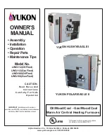
Figure 1

M952V060BU36AA
M952V080BU36AA
M952V100CU48AA
M952V120DU60AA

M952V060BD36AA
M952V080BD36AA
M952V100CD48AA
M952V120DD60AA

18-CD37D1-2-EN

M952 Upflow models can also be used in the 

Horizontal Left configuration.
M952 Downflow models can also be used in the 

Horizontal Right configuration.

M952 Furnace

OPTIONAL ACCESSORIES

Model Number

Description

BAYBASE205

Downflow subbase for downflow models only

BAYFLTR200

External side filter rack

BAYFLTR203

Filter kit horizontal for 17.5" cabinet

BAYFLTR204

Filter kit horizontal for 21" cabinet

BAYFLTR205

Filter kit horizontal for 24.5" cabinet

BAYFLTR317

Cleanable filter for 17.5" cabinet upflow only

BAYFLTR321

Cleanable filter for 21" cabinet upflow only

BAYFLTR324

Cleanable filter for 24.5" cabinet upflow only

BAYLPKT210B

Propane conversion kit

BAYLPSS210B

LP kit with stainless steel burners

BAYMFGH100A

Manufactured / mobile home kit

BAYRACK960A

Internal filter rack kit for upflow models

BAYAIR30AVENTA

Concentric vent kit for 2,2.5,3" vent system

BAYVENT200B

Sidewall vent termination kit for direct vent furnaces

BAYVENT500A

Side vent kit for downflow models only

BAYSWT10AHALTA

High altitude switch kit - UF/DF 060

BAYSWT08AHALTA

High altitude switch kit - UF/DF 080-120

KIT09224

Filter clip kit

BAYBRCKFLT10

Downflow bracket kit

ALL phases of this installation must comply with

NATIONAL, STATE AND LOCAL CODES

IMPORTANT — This Document is customer property and is to

remain with this unit. Please return to service

information pack upon completion of work.

© 2014 Ingersoll Rand All Rights Reserved

A341624P18

Summary of Contents for M952V060BD36AA

Page 1: ...ble filter for 17 5 cabinet upflow only BAYFLTR321 Cleanable filter for 21 cabinet upflow only BAYFLTR324 Cleanable filter for 24 5 cabinet upflow only BAYLPKT210B Propane conversion kit BAYLPSS210B L...

Page 2: ...llow safety warnings exactly could result in a fire or explosion causing property damage personal injury or loss of life Do not store or use gasoline or other flammable vapors and liquids in the vicin...

Page 3: ...rritation PRECAUTIONARY MEASURES Avoid breathing fiberglass dust Use a NIOSH approved dust mist respirator Avoid contact with the skin or eyes Wear long sleeved loose fitting clothing gloves and eye p...

Page 4: ...to check all connections as specified in the Gas Piping section of these instructions on page 31 6 Always install the Furnace to operate within the Furnace s intended temperature rise range with a duc...

Page 5: ...STALL THE FURNACE DI RECTLY ON CARPETING TILE OR OTHER COMBUSTIBLE MATERIAL OTHER THAN WOOD FLOORING CAUTION Do NOT install the Furnace in a corrosive or contaminated atmosphere Failure to follow this...

Page 6: ...7 1 2 2 M952V100CU48A 21 2 1 2 19 3 4 19 1 2 9 3 M952V120DU60A 24 1 2 2 15 16 23 1 4 23 10 3 SUFFIX LETTER MAY BE A Z NOTES 1 M952V120DU60AA REQUIRES 3 DIAMETER PIPE M952V100CU48AA REQUIRES 2 1 2 OR...

Page 7: ...de Figure 3 Downflow Outline Drawing MODEL SEE NOTE 1 2 DIM A DIM B DIM C DIM D M952V060BD36A M952V080BD36A 17 1 2 2 1 4 16 1 4 16 M952V100CD48A 21 2 1 2 19 3 4 19 1 2 M952V120DD60A 24 1 2 2 15 16 23...

Page 8: ...e in the horizontal position by placing the Furnace on the left side as viewed from the front in the vertical position The horizontal Furnace installation in an attic should be on a service platform l...

Page 9: ...meets the criteria for an unconfined space The total input of all gas utilization equipment installed in the combined space shall be considered in making this determination Refer to Table 4 for minimu...

Page 10: ...high volume of air will produce audible noise which could be objectionable when the unit is located very close to a living area It is often advisable to route the return air ducts under the floor or t...

Page 11: ...furnace must be removed for bottom return air After removing the filter lay the fur nace on its back Remove the two 5 16 hex screws secur ing the front of the bottom channel to the cabinet Rotate the...

Page 12: ...17 e Reinstall the furnace filter in the bottom position by inserting the chamfer end first into the filter rack ALTERNATE FILTER RACK INSTALLATION FOR SIDE RETURN AIR ON UPFLOW FURNACES Left or Right...

Page 13: ...or Return Filter Rack Installation With Side Furnace Cabinet Side Figure 19 CHAMFER END OF FILTER GOES INTO FILTER RACK FIRST Airflow Figure 22 Typical Horizontal Filter Installation Figure 23 BOTTOM...

Page 14: ...ples for location of the furnace clips Side return only Pre drill clearance holes with a 3 16 drill Bottom return holes are pre drilled 2 Install the clips in front and rear of the desired location us...

Page 15: ...obtain maximum efficiency from a condensing Furnace Proper installation of the vent system is necessary to assure drainage of the condensate and prevent deterioration of the vent system American Gas A...

Page 16: ...le pressure zone applications see Figure 30 The following are EXAMPLES ONLY EX 1 Example 1 shows that the vent may go vertical while the inlet air may be on any side of the structure The vent pipe wou...

Page 17: ...e the pipes to be removed later without cutting Be sure to properly support these joints Commercially available solvent cement for PVC must be used to join PVC pipe fittings Follow instructions on con...

Page 18: ...ULAR CORE 3 180 ASTM F628 DuraVent PolyPro 45 ASTM STANDARD PIPE TYPE ALLOWABLE TEMPERATURE MARKING NA NA 230 ULC S636 1 Allowable temperatures based on classifications covered in ASTM D4396 Deflectio...

Page 19: ...LENGTHS 2 Minimum vent length for all models 3 horizontal or 3 vertical 3 DO NOT MIX PIPE DIAMETERS IN THE SAME LENGTH OF PIPE OUTSIDE THE FURNACE CABINET Except adapters at the top of the furnace If...

Page 20: ...g NOTE Vent termination kit BAYAIR30AVENTA or BAYVENT200B may be used in addition to the horizontal and vertical termination options shown in the following figures For Canadian applications venting sy...

Page 21: ...licensed professionals for the installation of hard wired carbon monoxide detectors HORIZONTAL VENTING THROUGH WALL These Furnaces may be installed as direct vent as shipped or as nondirect vent Inst...

Page 22: ...hall have a period of thirty 30 days to comply with the above requirements provided however that during said thirty 30 day period a battery operated carbon monoxide detector with an alarm shall be ins...

Page 23: ...RTV SILICONE SEALANT CLEARANCE 0 ACCEPTABLE FOR PVC VENT PIPE 1 ACCEPTABLE FOR TYPE 29 4C STAINLESS STEEL VENT PIPE Figure 39 MAINTAIN 12 IN 18 IN FOR CANADA MINIMUM CLEARANCE ABOVE HIGHEST ANTICIPAT...

Page 24: ...o the building Figure 40 TYPE 29 4C STAINLESS STEEL VENTING THROUGH UNUSED CHIMNEY Figure 41 VENTING ROUTED THROUGH A MASONRY CHIMNEY PVC PLASTIC VENTING THROUGH UNUSED CHIMNEY SUPPORT THE SINGLE WALL...

Page 25: ...a height 15 feet 4 5 m above the meter regulator assembly I Clearance to service regulator vent outlet 3 feet 91 cm J Clearance to nonmechanical air supply inlet to build ing or the combustion air inl...

Page 26: ...6 feet 1 83m 3 feet 91 cm above if within 10 feet 3m horizontally L Clearance above a paved sidewalk or paved driveway located on public property 7 feet 2 13 m M Clearance under veranda porch deck or...

Page 27: ...onnections by turning the trap and extending the tubing to the lower right front corner of the Furnace Trim all excess tubing to avoid kinking The connecting tubing for left or right side condensate d...

Page 28: ...ain tube at the header Evaporator and Furnace condensate drain piping may be manifolded together as shown in Figure 46 A primary drain vent stack must be installed and terminated below the outlet of t...

Page 29: ...from the trap to the side of the unit and trim all excess tubing to avoid kinks Downflow furnace Use RTV silicon sealant to connect the fitting to the trap for ease of removal when cleaning the trap F...

Page 30: ...causing slippery conditions that could lead to personal injury Excessive draining of conden sate may cause saturated ground conditions that may result in damage to plants NOTE Use 1 2 or larger PVC or...

Page 31: ...UTOMATIC GAS VALVE WITH MANUAL SHUT OFF GROUND UNION JOINT DRIP LEG Figure 55 THE DOWNFLOW VERTICAL MAY BE INSTALLED LEFT OR RIGHT SIDE GAS PIPING GROUND UNION JOINT AUTOMATIC GAS VALVE WITH MANU AL S...

Page 32: ...und joint union and a manual shut off valve as shown in Figures 43 44 National codes require a condensation drip leg to be installed ahead of the controls as shown in Figures 55 56 The furnace and its...

Page 33: ...unit is derated for high altitude d Replace and tighten the regulator cover screw securely 7 Cycle the valve several times to verify regulator setting a Repeat steps 5 7 if needed 8 Turn off all elec...

Page 34: ...he burner box The burner box pressure tap equalizes the gas valve pressure regulator Manifold pressure is checked by installing a tee field supplied in the tubing between the tee coming from the burne...

Page 35: ...r leaks with a soapy solution DO NOT CHECK WITH AN OPEN FLAME Allow 5 minutes for any gas that might have escaped to dissipate LP Gas being heavier than air may require forced ventilation Turn the tog...

Page 36: ...h 6 When a single stage heating thermostat without fan switch is used no wiring on G terminal is used 7 W1 and W2 must be jumpered together for proper operation Second stage heat will begin based on I...

Page 37: ...off delays 9 Optional humidistat is to be connected between R and BK Factory installed jumper R to BK on the circuit board must be cut if optional humidistat is used The jumper must also be cut when...

Page 38: ...B C TO 115 V 1 PH 60 HZ POWER SUPPLY PER LOCAL CODES HUM SEE NOTE 5 EAC SEE NOTE 5 FIELD WIRING DIAGRAM FOR VARIABLE SPEED 2 STAGE FURNACE 1 STAGE HEATING 1 STAGE COOLING USING A 1 STAGE HEATING 1 ST...

Page 39: ...JUMPER SEE NOTE 9 From Dwg B342020 Rev 0 B C B C TO 115 V 1 PH 60 HZ POWER SUPPLY PER LOCAL CODES HUM SEE NOTE 5 EAC SEE NOTE 5 FIELD WIRING DIAGRAM FOR VARIABLE SPEED 2 STAGE FURNACE 2 STAGE HEATING...

Page 40: ...nd multi zone system controller On single speed cooling only non heat pump systems jumper Y to O for proper operation of the delay profiles and the Humidistat For two compressor or two speed systems j...

Page 41: ...stment Preliminary Inspections WARNING ELECTRIC SHOCK HAZARD DISCONNECT POWER TO THE UNIT BEFORE REMOV ING THE BLOWER DOOR ALLOW A MINIMUM OF 10 SECONDS FOR IFC POWER SUPPLY TO DISCHARGE TO 0 VOLTS FA...

Page 42: ...et at 60 100 140 or 180 seconds The factory setting is 100 seconds See unit wiring diagram Cooling The fan delay off period is set by dip switches on the Integrated Furnace Control The options for coo...

Page 43: ...tablish operation in First Stage 2 LOSS OF FLAME If loss of flame occurs during a heating cycle or flame is not present at the sensor the flame control module will close the Gas Valve The Integrated F...

Page 44: ...o call for Heat Flashing Fast Normal Call for Heat Fault Code Reset The last 4 fault codes can be erased from memory by powering up the control with G energized and then applying R to the W1 terminal...

Reviews: