background image


InfraTec GmbH 
Infrarotsensorik und Messtechnik 
Gostritzer Straße 61 – 63 
01217 Dresden/GERMANY


Phone 

+49 351 871-8615 

Fax 

+49 351 871-8727 

Email [email protected] 

 www.InfraTec.de


© InfraTec


2016  

(All mentioned product names and trademarks remain the 
property of their respective owners.) 
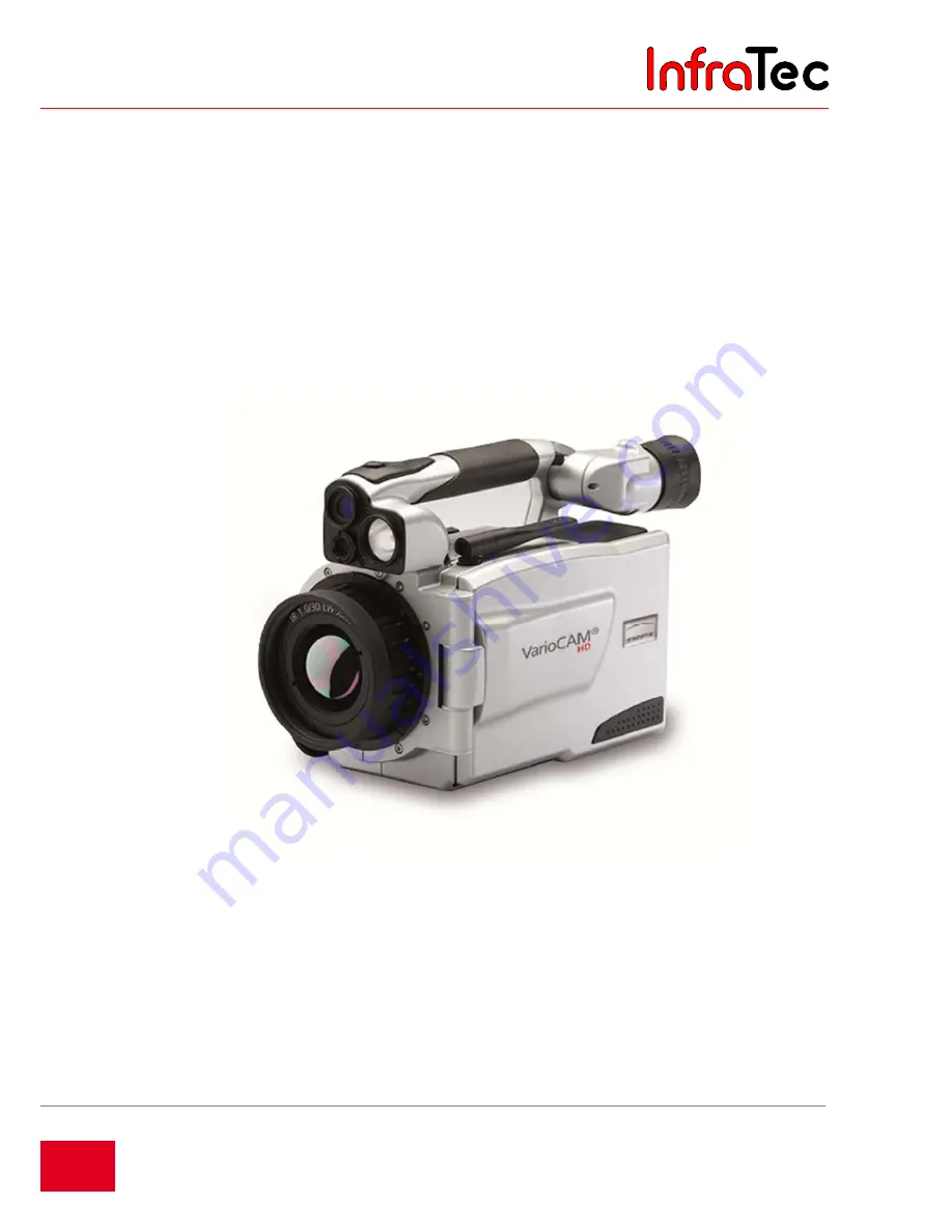


VarioCAM

®

 HD


User Manual 


State: March 2016 


InfraTec

Summary of Contents for VARIOCAM HD

Page 1: ...63 01217 Dresden GERMANY Phone 49 351 871 8615 Fax 49 351 871 8727 Email service InfraTec de www InfraTec de InfraTec 2016 All mentioned product names and trademarks remain the property of their respective owners VarioCAM HD User Manual State March 2016 I n f r a T e c ...

Page 2: ...I n f r a T e c ...

Page 3: ...eck 18 6 6 2 Quick saving 19 6 7 Menu functions 19 6 8 Shutdown and Standby 19 6 9 Data transmission to the computer 20 6 10 Analysis using the analysis software IRBIS 3 20 7 Start up 21 7 1 Adaptation of the shoulder belt 21 7 2 Adaptation of the hand strap 21 7 3 Using a tripod 21 7 4 Connecting a power supply 21 7 5 Inserting a memory card 22 7 6 Replacing the lens 22 7 7 Operation using the gi...

Page 4: ...ture of the VarioCAM HD 46 9 2 1 1 Automatic directory structure default setting 46 9 2 1 2 Individual directory names 47 9 2 2 Menu item Load 47 9 2 2 1 Loading individual files from file list or gallery 47 9 2 2 2 Loading and Playing Sequence Files 50 9 2 2 3 Loading and Playing Video Files 51 9 2 3 Menu item Save 51 9 2 3 1 Real time saving 51 9 2 3 2 Video saving 52 9 2 3 3 Automatic save Auto...

Page 5: ... 9 4 6 Menu item Alarm 73 9 4 7 Menu item Configuration 74 9 4 8 Menu item System 75 9 4 8 1 Display Setting 76 9 4 8 2 Regional Setting 76 9 4 8 3 Date Time Setting 77 9 4 8 4 Menu layout Setting 77 9 4 8 5 Menu control 78 9 4 8 6 Network 78 9 4 8 7 Info 79 10 Software installation 83 10 1 Installation instructions 83 10 2 Installation of WinPcap 83 10 2 1 Setting the network adapter 86 10 2 2 Se...

Page 6: ... described herein Equipment dependent features are identified accordingly by means of an within this user manual As a matter of principle the descriptions of the technical data and the specific scopes of functions and delivery in the corresponding shipping documents are decisive order confirmation bill of delivery This product is subject to further developments within the meaning of technical prog...

Page 7: ...llection using GigE Vision allow for using the VarioCAM HD in the most different fields of application The VarioCAM HD is equipped with a digital color video camera in order to document the measuring situation on photos Infrared IR and visual VIS image as well as frame rates can be saved to SD and SDHC Secure Digital High Capacity cards For the purposes of visualisation the thermography system is ...

Page 8: ...is inadmissible and will result in the forfeiture of any warranty claims Only use accessories or spare parts expressly recommended by the manufacturer regarding the VarioCAM HD Otherwise malfunctions or damages may occur Any warranty claims are excluded for such damages Standards directives VarioCAM HD meets the requirements of the following standards EN 60950 1 2006 Einrichtungen der Informations...

Page 9: ...r other high energy radiation sources from indirectly coming into the field of view of the VarioCAM HD using reflecting surfaces When the VarioCAM HD is not used the supplied protective lens cap must be attached at all times Only use SD and or SDHC memory cards in the SD drive of the VarioCAM HD Otherwise damages to the thermography camera or the memory card may occur which no liability will be as...

Page 10: ...e available as interfaces Specific software packages are required in order to use these interfaces present depending on the equipment 3 2 Description of the functional units Lens The camera lens collects the IR radiation in the field of view emitted by the measuring object and reproduces this IR radiation on the detector array Field of view FOV Field of View and resolution measuring spot size IFOV...

Page 11: ...raphy system reproduces the thermal radiation from the scene onto these detector elements and these detector elements absorb this radiation The temperature change of the detector elements resulting thereof results in signals that can be analysed electronically read out line by line and column by column using a read out circuit The use of an uncooled detector ensures the quick availability of the c...

Page 12: ...he controls of the VarioCAM HD are arranged for single hand operation with the right hand Another multi function button can be found at the top of the handle When carrying the camera on its handle it can be operated using the thumb of your right hand Specific modes of camera operation and presettings can be configured using menus Chapter 8 Operation page 26 contains a detailed description of how t...

Page 13: ...tenna Bluetooth external antenna Simultaneously using several interfaces on the 14 pin LEMO socket is allowed for by means of a breakout box In this case the breakout box is also used for external power supply As an alternative to the digital high resolution DVI D image data on the HDMI socket the analogue image data 4 3 PAL NTSC is available as FBAS signal composite on the 14 pin LEMO socket The ...

Page 14: ...le battery based operation Up to approx 3 h Working temperature range 25 50 C activation temperature 15 C Storage temperature range 40 70 C Moisture during operation and storage Relative humidity 5 to 95 non condensing Dimensions with normal lens 210 x 125 x 155 mm Weight with normal lens 1 7kg Tripod connection 1 4 photo thread Attention observe max penetration depth of 4 5mm DIN 4503 Display Day...

Page 15: ...igital colour video camera Depending on the equipment laser rangefinder laser pointer GPS 2 x rechargeable lithium ion battery NP QM91D Sony Battery charger SDHC card Card adaptor for SD card Protective lens cap Shoulder strap User manual VarioCAM HD Quick user guide Transport box transport packaging Optional accessories Wall plug transformer 15 with 14 pin LEMO connector Replacement lenses macro ...

Page 16: ...iew USB port SD card slot Colour TFT display Rechargeable lithium ion battery Lens LEMO socket 8 pin for GigE Vision interface blue mark LED video light WLAN Bluetooth Laser rangefinder Color TFT viewfinder for diopter compensation turn eyecup Carrying handle LEMO socket 14 pin power supply trigger FBAS DVI port Colour video camera GPS Antenna I n f r a T e c ...

Page 17: ...k Focus rocker switch with autofocus function Temperature Auto Multi function button Multi function button Save All buttons can be used for multiple functions triggered either by Half or full pressing and and or Short or long pressing and The button function can be changed by changing the settings in menu Settings Buttons 6 1 Preparation You will need the following equipment VarioCAM HD Rechargeab...

Page 18: ...n green indicates that the VarioCAM HD is ready to operate in Live mode Fig 3 Camera start system initialisation indication 6 3 Display Fig 4 Arrangement of the image elements Initially you must select a motif with a contrasty scene e g an active electrical device and point the VarioCAM HD towards this scene When using the viewfinder fold the display to the side of the camera The viewfinder is swi...

Page 19: ...angle Fig 5 Display when using autofocus Fig 6 Display after autofocus 6 5 Setting the temperature range Push the button shortly The thermography system will automatically set a temperature scale of the false colour image corresponding to the current scene Fig 7 Overloaded and underloaded thermal image Fig 8 Image after temperature range adaptation The required temperature scale can also be set by...

Page 20: ...the temperature scale can be adapted automatically once by shortly pushing the Enter button If the Enter button is pushed longer the scale is permanently adapted automatically The AUTO mode will then be displayed by on the right side of the image above the color palette The AUTO mode is terminated by any manual setting of Level Range Max Min 6 6 Saving images In order to save the thermal image the...

Page 21: ...stick to navigate the menu and select the functions using the Enter button The 4 main menus can be selected by means of tabs located on the upper margin of the menu and identified with the corresponding symbols Image File Measure Settings Sub menus can be opened by using the button Enter on the respective menu item e g push the button in order to open the sub menu for manually setting the temperat...

Page 22: ...nction is executed in the File menu The desired palette of colours on the right hand side of the thermography image is selected by using the drop down field on the right top of the temperature scale The View menu can be used in order to display further elements in addition to the thermography image e g comment field parameters and VIS image The desired temperature scale can be set by using the sli...

Page 23: ...itially adjust the hand strap attached to the handle piece as required For this open the loop of the hand strap and adjust the length of the belt strap in such a way that you can comfortably access the controls with your fingers Then close the hook and loop fastener of the loop 7 3 Using a tripod The thermography camera is equipped with a 1 4 photo thread DIN 4503 on the bottom of the housing In o...

Page 24: ...aligned In this position the lens must be pressed slightly against the camera corpus and turned clockwise until the red dot of the lens is aligned with the white dot of the camera 7 7 Operation using the gigabit Ethernet GigE interface Please proceed as follows in order to connect the VarioCAM HD to a PC notebook The accessories described are contained in the scope of delivery as an option The Eth...

Page 25: ...3 7 8 Operation using breakout box connection via RS232 Using the breakout box will expand the connection options of the VarioCAM HD The interfaces 2 x analogue output 2 x trigger E A PAL NTSC FBAS as well as the digital RS232 interface are accessible via the breakout box Please follow the specified steps on how to establish the required connections 1 Initially the connection between thermography ...

Page 26: ... 9 1 Trigger function Triggering uses the Ethernet to affect the 16 bit IRB data transmission The TTL CMOS signal is forwarded to the VarioCAM HD right hand side socket using the BNC sockets marked T1 and T2 of the breakout box and from there using the connecting cable with 14 pin LEMO connector In order to connect the trigger signal sources to the breakout box commercially available BNC cables ma...

Page 27: ... in order to allow an unambiguous assignment to the current frame Depending on the event signals can be generated via T1 and T2 using the alarm functionality The appropriate setting for this is described in section 9 4 6 Menu item Alarm page 73 7 9 2 SyncOut The frame rate of the VarioCAM HD cannot be controlled from the outside In order to synchronise other cameras and processes and for active th...

Page 28: ...22 Representation of the controls All buttons can be used for multiple functions triggered either by Half or full pressing and and or Short or long pressing and Within the framework of the description of the camera functions the letter L is attached to the symbol of the respective function button if a button must be pushed for a longer period of time Example Shortly pressing the T button Long pres...

Page 29: ... save button can be used in order to immediately accept inputs in many menus This function shortens the navigation and is activated ex factory but can also be deactivated see chapter 9 4 8 Menu item System page 75 The multi function joystick can be used to navigate and to select functions to input using the arrow buttons as well as the function Enter push the center The focus rocker switch can be ...

Page 30: ...r upper edge of screen Date and system time Camera status Upper right corner of the screen Current mode of operation Temperature scale Right edge of the screen Assignment of the colors shades of grey of the image to the temperature range shown Measured values table Left screen area Display of temperature values Status symbols Lower screen area right Status indicators for Power supply wall plug tra...

Page 31: ...e alarm indicators messages regarding critical status of the rechargeable battery Please wait etc Fig 25 Autofocus indication Fig 26 Rechargeable battery warning message Fig 27 Message Please wait loading calibration The VarioCAM HD can be operated both by the control directly attached to the camera and depending on the equipment remotely using GigE RS232 or WLAN 8 2 2 Setting the temperature scal...

Page 32: ... and automatic focus without laser range finder The focus rocker switch can be used in order to Manually focus by Pushing the left side of the focus rocker switch in order to change the focus to longer distances and or Pushing the right side of the focus rocker switch in order to change the focus to shorter distances You can also set the focus automatically by pushing the center function of the fo...

Page 33: ...e constantly repeated and in case of any distance changes the focus set up will be adjusted accordingly In order to activate the laser range finder function with a permanent supported autofocus LRF PAF select the menu Measurement Fig 29 Selection function LRF PAF Permanent laser range finder supported autofocus The use of the function permanent laser range finder supported autofocus is limited to ...

Page 34: ...he camera The VarioCAM HD supports commercially available SD and or SDHC cards up to a capacity of 32 GB Depending on the detector format and the set memory format up to 25 000 thermograms can be saved to one SDHC card this way Along with individual thermograms thermal image sequences can be saved as digital raw data and video sequences The particular description of the camera settings for data st...

Page 35: ...wn again in mode is ignored Push the button completely the image is saved The process of writing the data is indicated by the changing colour of the map symbol in the line below the image right hand side Upon saving the camera control automatically re activates the Live mode 8 2 5 2 Quick saving Using the VarioCAM HD you can immediately save images in the Live mode or directly from the motion Imme...

Page 36: ...Thermography System VarioCAM HD 8 Introduction 34 InfraTec GmbH 2016 User Manual Fig 33 Thumbnails IR and VIS I n f r a T e c ...

Page 37: ...ed to navigate to the top and or to be bottom The main menus can be switched using the buttons and Depending on the settings for Menu control made in the Settings menu in the System menu item at the Menu control function see chapter 9 4 8 Menu item System page 75 the lower menu in each case can be accessed directly by pushing from the very top and or the upper menu in each case can be accessed dir...

Page 38: ... minimum values of the currently set temperature range are indicated by the corresponding figures above and below the arranged colour palette 3 different modes can be selected for manually setting the temperature range in the Manual menu item Fig 40 Menu selection for manually setting level range Fig 41 Menu selection for manually setting maximum minimum Fig 42 Menu selection for numerical tempera...

Page 39: ...ge to the temperature scale or non recurrent triggering of the Autoimage function The setting menus Level Range and Maximum Minimum can be accessed directly by the button functions Long and Long as set ex factory 9 1 2 Menu item Mode In Live mode the VarioCAM HD displays thermal images Infrared images video images Digital images or the superimposition of both Merge The options can be selected in t...

Page 40: ...ion Enhancement RE or Dynamic Resolution Enhancement DRE These modes must be activated in the Settings menu using the Extras menu item Digital image mode In the Digital image mode the camera internal digital photo channel is operated in video mode and displayed with a geometric resolution of 1 024 x 720 pixels The option of saving photos with the available pixel resolution of 3 264 x 2 448 pixels ...

Page 41: ...erature scale Therefore cross fading refers to the surface area In the Interval Above and Below Merge modes the displayed temperature range can be restricted cross fading depends on the temperature in the entire infrared image Merge Interval In the Interval Merge mode a partial temperature interval is defined within the set temperature range Partial areas the temperatures of which are within this ...

Page 42: ...ing setting 9 1 3 Menu item Zoom Depending on the equipment the VarioCAM HD supports digital magnification of the Infrared image and the Digital image VIS image up to 32 fold The setting is made in the Fig Setting Fig menu using the Zoom menu item and is applicable to the currently displayed image in each case Infrared image or VIS image A set magnification is indicated as the corresponding status...

Page 43: ...IRB format 9 1 4 Menu item Palette The current allocation of the individual colors shades of gray of the false color representation to the corresponding temperatures is performed by using the palette shown on the right hand side margin of the screen colour scale see Fig 24 Arrangement of the image elements page 28 In this the maximum value of the image area above and its minimum value below the pa...

Page 44: ...hite palette the representation is inverted The low temperatures are now indicated in lighter colours and the higher temperatures are now indicated in darker colours see also Fig 67 The 16 steps function can be used to set the representation of the palette from 256 colour steps to 16 steps Accordingly only 16 temperature levels can be indicated instead of 256 which is why differentiations exceedin...

Page 45: ...kmark using the Enter button of the joystick the dialog can also be navigated with the joystick When selecting the Hide menu item all image elements of the graphical user interface are hidden at once If this function is activated a checkmark will be shown on the right side of the Hide menu item Fig 71 Menu item Image elements dialog Image elements 9 1 6 Menu item Isotherms In the Image menu using ...

Page 46: ...ally in a dialogue To do so open the isotherms editor by pressing T Figure 71 Isotherms editor In this dialogue changing the colour of the isotherm is also possible The 15 special colours designed for the isotherms were selected in such a way that they can still be conceived as isotherm even when using a colour palette Regardless of the aforementioned and for the purposes of unambiguous allocation...

Page 47: ...m Filter Fig 78 Menu item Filter With the help of the Filter menu item a filter can be set for the representation of the thermal images A first order digital low pass filter is used as a filter The sub menu can be used in order to select from the four filter stages Off Weak Medium and Strong Filtering reduces the noise in the image significantly improving the image quality particularly for scenes ...

Page 48: ...e and directory names cannot be specified by the user Fig 80 Automatic directory structure The name of the subdirectory is generated from the current data always two letters for year month and day as well as two letters for continuous identification for example on 22 06 2012 the first directory would be named 120622AA In the directory the files are numbered consecutively starting from 00 up to 99 ...

Page 49: ...tomatic directory creation e g AA AB AZ BA BB BZ ZZ In this way 26x26 directory names with the same root name can be created Individual directory names have only four characters consisting of the indicators AA ZZ of each directory name and serial numbers from 00 99 Fig 82 Directory files with individual directory names If more individual directory names are assigned to one memory card identical fi...

Page 50: ...gle file selection of thermogram and visual image The button can be used in order to highlight files and directories and the button can be used to delete files and directories In order to avoid any accidental loss of data the process of deleting files must be confirmed in a dialogue Fig 86 Dialog Delete file The file selected from the file list highlighted blue is displayed large by using the Ente...

Page 51: ...int correspond to the functions of the single image display see above see also Fig 87 and Fig 88 Possible is then for example the change of the representation scale of the loaded image For subsequent processing of the opened enlarged images of Single file or gallery the Enter button must be pushed again When charging the status indicator in the upper right corner of the image changes accordingly W...

Page 52: ... quick selection of the desired playback point within longer sequences the starting point can be marked with in 10 increments see Fig 93 The playback is started and paused with stops the playing and returns you to view the file list or gallery display Fig 93 Loaded sequence file Fig 94 Play sequence file Play is marked in the top right of the image area by the button while in the lower part of the...

Page 53: ...e name of the video file is displayed simultaneously under the video image see Fig 95 9 2 3 Menu item Save Along with single image saving the save button of the VarioCAM HD can be used to save the following depending on the equipment Thermal image sequences with the maximum frame rate real time saving Real time Series of single images thermal image and photo Autosave Video sequences thermal image ...

Page 54: ...mps in the header When geometrically allocating the thermal image sequence to a photo of the scene it is recommendable to install the VarioCAM HD on a tripod in a stationary manner and to save a photo before or after real time saving in Merge mode Fig 97 Real time saving indication 9 2 3 2 Video saving If the saved data of a serial measurement does not require any radiometric editing or if display...

Page 55: ...e detector format and the properties of the used SDHC card just like with real time saving Fig 98 Menu item Save Fig 99 Automatic save In order to start automatic saving the start time date time and the saving interval and the number of thermograms to be saved must be defined initially As an alternative to Interval and Count the duration of series saving otherwise calculated from the values for in...

Page 56: ...rd for entering alphanumeric characters whereby this keyboard is shown by pushing the Enter button in the comment line The keyboard can simply be navigated with the joystick Capital and lower case letters are switched similarly to a computer keyboard There is an additional keyboard page for numbers and selected special characters A maximum of 50 characters can be entered The number of the current ...

Page 57: ...m Saving format Fig 106 Menu item Saving format Fig 107 Setting the saving format Using the Saving format menu item data to be saved in addition to the thermal image and its format can be selected and furthermore settings to be made in connection with the process of saving can also be selected For this a dialogue is shown see also Fig 107 The following table shows the selectable settings Selection...

Page 58: ...isplayed temperature maximum and temperature minimum It is possible to display the global temperature maximum and or temperature minimum within the thermal image by selecting the options Maximum and Minimum Position and value are consistently updated within the image Regardless of the palette selected for false colour representation the maximum is red and the minimum is blue The maximum and minimu...

Page 59: ...1 Menu item measurement definitions no ROI created Fig 112 Menu item measurement definitions ROI created Fig 113 Menu item measurement definitions ROI hidden Fig 114 Menu item measurement definitions identifier of ROI hidden The following shapes of the measuring objects can be selected Point P Line L Polygon line PL Rectangle R Ellipse Polygon PG In order to create a new ROI you must initially ope...

Page 60: ...ter the red mark on the point is no longer visible While the measuring objects are being moved the measured value is not updated 9 3 2 2 Line L The position of the measuring line can be defined by moving one of the terminal points or by synchronously moving both terminal points simultaneously The respective active point and or both points are also marked red in this see Fig 119 Fig 118 ROI selecti...

Page 61: ...he joystick by changing the position of the marked spot see Fig 123 and Fig 124 If the position of the rectangle is to be changed please initially push the Enter button The rectangle is then highlighted by a red dot in its center and can be moved using the joystick without any changes to its shape see Fig 125 Fig 123 Rectangle change size Fig 124 Rectangle change size Fig 125 Rectangle move 9 3 2 ...

Page 62: ...sed longer in order to create the next point starting from the active point in a clockwise direction which can then be moved with the joystick and saved by pressing Enter When all points are highlighted the polygon plane can be moved without any changes to its shape Fig 134 Fig 129 Polygon moving the starting point Fig 130 Polygon creating a new point Fig 131 Polygon moving a new point Fig 132 Pol...

Page 63: ...tputs are short circuit proof but should be completed to high impedance for use of temperature proportional voltage R 1 MΩ The digital to analogue conversion is performed with a resolution of 8 bits so that the values range from 1 5 V dissolved by 255 steps with a minimum step width of 15 686 mV The voltage output voltage always refers to the currently used calibration see chapter 9 4 1 Menu item ...

Page 64: ...ximum or minimum The assignment of average maximum or minimum for analogue output is done by choosing from the measured value display For the settings the following rules apply Analogue value output depends on Measured value display Mean Mean or no selection Maximum Maximum mean value must not be selected Minimum Minimum average and or maximum must not be selected If additional display are shown t...

Page 65: ...properties of the measuring object as well as of the ambient conditions and the measurement setup is required The correction parameters are accepted globally for the entire image Fig 144 Menu item Correction Fig 145 Settings Correction The VarioCAM HD works with a wavelength range of 7 5 14 µm The influence of the atmosphere on the measurement result can be neglected during the majority of the mea...

Page 66: ...ee chapter 8 2 1 Elements of the user interface page 28 and saved within the thermal image The laser rangefinder LRF integrated into the VarioCAM HD allows for precise distance measurement up to a distance of approx 70 m see chapter 9 3 8 Menu item Laser page 66 If the Automatic option is selected the distance measured with the LRF before the image was recorded is saved to the thermal image once t...

Page 67: ...in the first information line in the Image elements menu see chapter 9 1 5 Menu item Elements page 43 When switching off the GPS receiver the first information line is hidden automatically Fig 150 Menu item GPS Along with latitude longitude and the number of satellites further GPS information is saved together with the thermal image height speed and bearing 9 3 7 Menu item WLAN VarioCAM HD has a W...

Page 68: ...optik logo simultaneously with an acoustic signal 2 x beep The laser pointer integrated depending on the equipment is activated analogueously With integrated variants without laser range finder measurement objects can be marked with a laser pointer without measuring the distance This function as well as LRF without updated distance measurements can be turned on off with the button Laser Fig 154 Me...

Page 69: ...Permanent LRF supported autofocus In order to correct the focus setting under constantly changing object distances the function LRF PAF permanent laser range finder supported autofocus can be activated for distances up to 70 m Here the distance of the measurement object is continuously measured by the laser range finder and compared with the previous distance For distance changes more than the cur...

Page 70: ...available ranges can be found in the Calibration menu item Fig 160 Menu item Calibration Depending on the object temperature and the measurement assignment the measuring ranges can be set manually or automatically However it must be ensured that the temperature of the current scene does not exceed the set range in order to avoid overloads within the thermogram The VarioCAM HD is equipped with a hi...

Page 71: ...this the size of the displayed image is reduced The sub frame formats are only for cameras with XGA detectors of 1 024 x 768 IR pixels that can be activated in the menu item image format Alternatively the settings for sub frame or calibration range can also be changed with the remote control menu of the Software IRBIS 3 online The functionality of VarioCAM HD is limited in the sub frame mode Data ...

Page 72: ...n the focus setting is changed gradually for shorter and further distances between the individual recordings In this way all parts contained in the current scene of the image can be captured sharply in at least one of the individual recordings When loading the Eversharp sequence IRBIS 3 calculates from the Eversharp sequence a deep sharp image The display of distance corresponds to the initial set...

Page 73: ...ately after start up of the VarioCAM HD the shutter interval is adapted automatically by the internal camera control depending on the change of the device temperature over the course of the first 5 minutes During this time the time specified for the Intervall option is ineffective In the Shutter Automatic mode the parameter sensitivity depending on the measurement situation and requirements can be...

Page 74: ... Reset NUC NUC and temperature scale in accordance with the scene For manually setting Level range For manually setting Maximum Minimum Long Laser on off Light on off halfway Real time saving Video saving Level range menu long Max Min menu long Zoom menu Isotherms menu Infrared Digital image Isotherms on off Minimum on off Maximum on off Minimum and Maximum on off long Switch over palette Invert p...

Page 75: ...arm condition is met or not For two measurement objects 1 ROI and 2 ROI temperature thresholds can be defined that apply to the average Avg temperature maximum Max or temperature minimum Min of the corresponding measurement object or the overall picture Global For each ROI and the corresponding temperature threshold a comparison is defined or where for max only and Min only selectable is If these ...

Page 76: ...vg Avg and Min 4 as audio alarm so that an acoustic differentiation of various alarms is possible When selecting OSD the alarm is shown on the display viewfinder Fig 174 Alarm indication when the average value is exceeded 9 4 7 Menu item Configuration You can save your individual device settings as device configuration in the VarioCAM HD This way you can configure and if required reload user and o...

Page 77: ...st possibly be re used at a later point in time we recommend saving a user configuration beforehand 9 4 8 Menu item System Fig 179 Menu item System The System menu item contains the settings and information about the basic functions of the VarioCAM HD Along with the settings for language date and time which as a rule must only be configured rarely it is possible to set the brightness of the viewfi...

Page 78: ...tly using the levels Bright Medium and Dimmed When the ambient lighting conditions are normal the brightness setting Medium is absolutely sufficient for the display in dark conditions the setting Dimmed should be selected The DVI D output can also be set with the formats 768 p and 800 p being the available selection options Regarding the FBAS interface TV output it is possible to toggle between th...

Page 79: ... selection options for the font size comprise the 3 levels Large Normal and Small Particularly in the event of a large font size a part of the text shown in the menus is no longer displayed completely because the available space is insufficient However when navigating to the corresponding menu item this menu item is displayed completely even when it exceeds the menu width When switching from day t...

Page 80: ...order to accelerate the navigation within the menu it is possible to navigate from the Settings menu directly to the Image menu using and vice versa using menu cycle Horizontal It is furthermore possible to navigate from the lower menu line directly to the first menu line using and vice versa using menu cycle Vertical In order to combine both variants you can select the sub menu Allover option in ...

Page 81: ... number of the camera the detector format information about current power supply as well as the camera temperature Fig 189 Info display of camera information The sub menu lens displays the type of the current lens serial number height and width of the image field as well as lens temperature not for lenses with screw thread Fig 190 Info display of lens information The sub menu SD card displays the ...

Page 82: ...ion VarioCAM HD is delivered with the latest firmware version However the firmware of the camera is constantly evolving and expanding the range of available operation functions If you go to the sub menu firmware update you will be able to update your camera s firmware version Further information about available updates can be found on InfraTec s website or by calling InfraTec s service hotline see...

Page 83: ...firmware update Start Update and confirm with OK Make sure you have a reliable power supply before you update your VarioCAM HD Connect the camera with the wall wart and insert a fully charged battery Please do not disconnect the camera from the power supply during the update Fig 194 Info Start Firmware update After starting the update the following display appears Fig 195 Info Display content afte...

Page 84: ...ent during the firmware update When the update is finished the display Update done appears and the camera turns off automatically When the camera is rebooted after this update an information field with the message the update was successful shows up Fig 197 Info display after firmware update I n f r a T e c ...

Page 85: ...rk in order to actuate the VarioCAM HD Depending on the used Ethernet adapter different configuration options will be available after the Ethernet adapter is installed We recommend using the internal GigE network card at all times for camera connection For the installation described below you must dispose of the access rights of the user group Administrators 10 2 Installation of WinPcap Upon execu...

Page 86: ...ermography System VarioCAM HD 10 Introduction 84 InfraTec GmbH 2016 User Manual Fig 199 Start of the installation Fig 200 Confirmation of the terms and conditions of the license agreement I n f r a T e c ...

Page 87: ...m VarioCAM HD 10 Introduction User Manual InfraTec GmbH 2016 85 Fig 201 Define automatic start of WinPcap Fig 202 Completion of the installation The installation is finished by clicking the Finish button I n f r a T e c ...

Page 88: ... 10 2 2 Setting the IP address Before configuring the network card for being used in connection with the camera the properties of the interface card to be used must be checked In this releasing non essential functionalities and assigning a fixed IP address are important The screenshots shown below provide an overview Fig 204 Properties of the LAN connection Please note that you only need the compo...

Page 89: ...Use the following IP address menu item During the further progress of the installation you will need two free network addresses Should you have any questions regarding this please contact your network administrator directly The Retrieve IP address automatically option must not be selected If this option is however activated the computer will try to retrieve a dynamic network address from the camer...

Page 90: ...roperty in order to achieve a trouble free Ethernet connection to the VarioCAM HD This function significantly reduces the occupancy rate of the network and allows for loss free data transmission even at high frame rates Fig 206 Setting Jumbo Packet Fig 207 Speed and duplex mode Please select the highest possible value from the available drop down list Please preferentially select the value 1 0 Gbi...

Page 91: ...ish the connection between camera and software Fig 208 Camera menu of the IRBIS 3 software The following Select camera dialogue must be used to select the camera type VarioCAM HD Clicking the Accept button will start the establishment of the connection to the thermography system Fig 209 IRBIS 3 Select camera All further functions of the program are described in detail in the manuals IRBIS 3 Infrar...

Page 92: ...s change the aperture of the camera housing must be protected against any kind of contact with the inner components It must be ensured that no dirt can penetrate the inside of the camera Interventions of any kind into the inside of the thermography camera are expressly prohibited Maintenance and repair work exceeding the actions and measures described within the framework of this user manual must ...

Page 93: ...ed circuit boards These components must be disposed of specifically when the device is at the end of its use The manufacturer offers to take back the VarioCAM HD product from the customer in order to ensure that the device is disposed of in an environmentally friendly manner when it is at the end of its use In this case please return the device to the address mentioned in chapter 14 Service page 9...

Page 94: ...facturer guarantees the implementation of the service on the VarioCAM HD product Should you experience any failures or require the performance of technical maintenance works please contact your dealer or customer services using the following address InfraTec GmbH Infrarotsensorik und Messtechnik Gostritzer Straße 61 63 01217 Dresden GERMANY Phone 49 351 871 8615 Fax 49 351 871 8727 Email service I...

Reviews: