background image

2MP Night Vision Bullet Camera 

Quick Installation Guide 

English Version 1.0 

IHB703 Series 

w w w . i n f i n i q u e . c o m 

Box Contents 

Read Before You Use  

1 x 2MP Night Vision Bullet Camera 

1 x 60ft Video and Power Cable with Connectors 

Mounting Screws, Installation Template 

Power Adapter *, Quick Installation Guide 

* Available only in 4 Camera Kits.  Power adapter with  

splitter is provided in 4 Camera Kits to power four cameras. 


Key Points 

Use the regulated UL / CSA / BIS approved power supply 

which has been supplied with the camera pack. Use of a 

non-regulated, non-conforming power supply can damage 

this product and voids the warranty. 

 

Before attempting to connect or operate this product, 

read the instructions carefully and save it for reference. 

 

All instructions should be followed for safe handling of the 

product. 

 

Camera should not be disassembled. 

 

Camera should not be focused directly towards sun or 

bright lights and where there are no obstructions. 

 

Camera should be installed where vandals cannot easily 

reach and the cable should be secured properly in ducts 

to avoid damage. 

 

Camera is for indoor and outdoor use, however when 

installed outdoors sheltered location is recommended. 

 

Camera should be operated within the given             

temperature and humidity range. 

 

Use the regulated UL / CSA / BIS approved power supply 

which has been supplied with the camera pack. Use of a 
non-regulated, non-conforming power supply can    

damage this product and voids the warranty. 

 

Use a damp cloth to clean the camera surface, do not 

use any harsh cleaners. 

 

The video and power supplied is rated for surface   

mounting only.  

Camera Features  

1.  Not intended for submersion in water. Installation in a 

sheltered location recommended. 

2.  This camera includes an Auto Mechanical IR Cut Filter. 

When the camera changes between Day/Night viewing 

modes, an audible clicking noise may be heard from 

the camera. This clicking is normal, and indicates that 

the camera filter is working. 

Disclaimer 

Infinique reserve the right to modify product specifications and 

prices without notice and without incurring any obligation. 


© 2019 Infinique Worldwide Inc. Canada 

Infinique is a registered trademark of Infinique Worldwide Inc. 
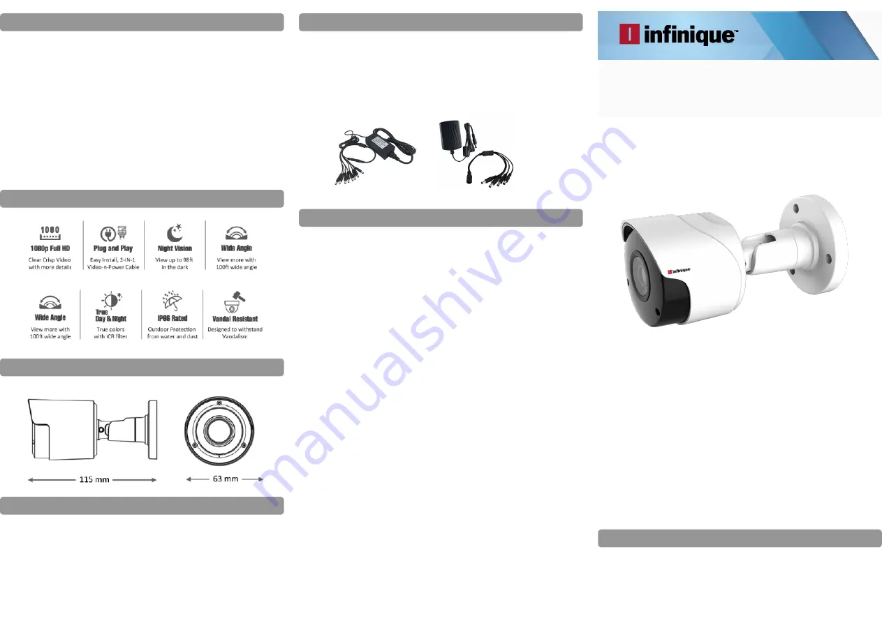
Power Adapter  

Two multi-camera power adapters options may be provided 

that provided depending on the product configuration.    

1.  2A 12V DC 4 Split Power Adapter to power 4 Cameras 

2.  4A or 5A 12V DC 8 Split Power Adapter to power 8 

     Cameras 

Camera Dimensions 

Summary of Contents for Hybrid AHD DVR

Page 1: ...use however when installed outdoors sheltered location is recommended Camera should be operated within the given temperature and humidity range Use the regulated UL CSA BIS approved power supply which has been supplied with the camera pack Use of a non regulated non conforming power supply can damage this product and voids the warranty Use a damp cloth to clean the camera surface do not use any ha...

Page 2: ...tion Cable Options The video and power cable provided with the camera covers a cable run distance of 60 feet If the cable provided is not sufficient alternate cables can be used depending on the cable type as shown below 1 RG59 Coaxial Siamese Cable for Video and Power 300ft or 91m max cable distance 2 RG59 Coaxial Cable for only Video 1000ft or 305m max cable distance Key Points If the cable run ...

Page 3: ...e however when installed outdoors sheltered location is recommended Camera should be operated within the given temperature and humidity range Use the regulated UL CSA BIS approved power supply which has been supplied with the camera pack Use of a non regulated non conforming power supply can damage this product and voids the warranty Use a damp cloth to clean the camera surface do not use any hars...

Page 4: ... as shown below 1 RG59 Coaxial Siamese Cable for Video and Power 300ft or 91m max cable distance 2 RG59 Coaxial Cable for only Video 1000ft or 305m max cable distance Key Points If the cable run distance is above 300ft 91m the power source should be near the camera If not the quality of video will be affected A single stretch of cable should be used between the Camera and the DVR Do not use cable ...

Page 5: ...on However all ports will be present but in different locations 4 Channel DVR back panel is shown 8 and 16 Channels back panels will have 8 and 16 video inputs to connect the cameras Monitors connected to the DVR can be either HDMI or VGA HDMI Cable is included in the pack to connect to the HDMI Monitor VGA cable is not included Connect the router to the DVR using the Ethernet Cable which is inclu...

Page 6: ...or auto Daylight Savings Time updates Step 3 Email Setup Email settings are required to receive the alert emails when events happen Internet connection is required to for the email alerts to work Enter the Email id and the other details required Step 4 IP Camera Setup Analog HD Cameras are automatically configured As this is a Hybrid DVR IP Cameras can also be connected Additional configuration wi...

Page 7: ... via 3G or above or WIFI Installation Search for the InfiViewCam App on Google Play Store for Android devices or App Store for iOS devices and install on your smart phone Run the app it will display the live view screen as shown below Add Recorder to Device List To add recorder select the menu icon and select Device List from the menu which will display the Device Manager Select the icon to add th...

Page 8: ...the QR code from recorder Information menu Once connected all the channels will be displayed Adding Recorder using Online Search In the Add New Device window Click on Online Search all the recorders connected to the same network will be listed in the Online Device display Select the required recorder from the list Once connected all the channels will be displayed ...

Page 9: ...e added to the Device List Edit Device Under Device interface click Device to view device information Edit device information Clicks save to save Remove devices Under Device Manager interface slide the device to left and then click Delete to remove it IP Address ID IP Address of the Recorder Media Port 9000 User Name admin default user Password Enter the recorder password Click Save ...

Page 10: ...o select channels and then click Start Live View icon to view the cameras If it is under multiple channels display mode you can drag the cameras to reorder the windows Icons on Live View are shown below PTZ Control Click to show PTZ control panel Icons Function Tab arrows to move camera side to side or up and down Set speed Set call or delete preset point Under PTZ control panel press the arrows t...

Page 11: ...intercom function click button can use this function Select and delete the live view channel Select and drag the channel to the upper side of the mobile phone screen until the background color of the upper side screen turn red and a garbage icon comes out Then the channel selected will be deleted Remote Playback Click to go to Remote Playback interface Start Playback Under Remote Playback interfac...

Page 12: ...face select device from device list to go to recording files interface and select the files you would like to replay Icons of Local Playback Icons Function Slow Play Play Pause Fast Forward Frame by Frame Stop Snapshot Mute on off Remove recording files Under Recording Files interface click edit to edit select one or multiple files which you would like to remove Click Delete to remove the files if...

Page 13: ...images or recording files Instructions Click Edit to select images you would like to remove Click Delete to remove or click Clear to clear images Image Manager Click an image to enlarge it to full screen You can click to display images automatically Click to remove images You can hold or separate fingers to zoom in out images Or double click to decrease or enlarge images Or slide the screen to vie...

Page 14: ...o connect or operate this product read the instructions carefully and save this manual for future use Important Safety Instructions Carefully read the following safety instruction to avoid personal injuries and prevent the equipment and other connected devices from being damaged RoHS ...

Page 15: ...r mishandling contact the authorized dealer for repairs Note Warranty is void in such cases Use standard lithium battery Note Use the batteries included or as specified by the manufacturer After cutting off the power supply if the system clock does not work replace the standard 3V lithium battery on the main board Warning Turn off DVR before replacing the batteries or you may suffer from serious e...

Page 16: ...t accept any interference received including interference that may cause undesired operations The lightning flash with an arrowhead symbol within an equilateral triangle is intended to alert the user to the presence of un insulated dangerous voltage within the product s enclosure that may be of sufficient magnitude to constitute a risk of electric shock to persons The exclamation point within an e...

Page 17: ...N 10 3 6 USING THE SUPPLIED MOUSE 10 3 7 USING THE VIRTUAL KEYBOARD 10 3 8 PASSWORD 11 4 DVR START UP 12 4 1 START WIZARD 12 4 2 NETWORK CONFIGURATION 12 4 3 DATE AND TIME 13 4 4 IP CAMERA 14 4 5 DISK 16 4 6 RESOLUTION 16 4 7 MOBILE 16 4 8 SUMMARY 17 5 LIVE VIEW SCREEN OVERVIEW 18 5 1 CAMERA QUICK TOOLBAR 19 5 2 TASKBAR 19 5 3 START MENU 20 5 4 UNLOCK AND LOCK SCREEN 20 5 5 SHUTDOWN 21 6 DVR SYSTE...

Page 18: ... CC Cross Counting 43 6 8 7 Intelligent Analysis 45 6 8 8 Intelligent Schedule 46 7 RECORD 47 7 1 ENCODE 47 7 2 RECORD PARAMETERS 48 7 3 RECORD SCHEDULE 49 7 4 CAPTURE 50 7 5 CAPTURE SCHEDULE 50 8 ALARM 51 8 1 MOTION 51 8 2 I O 51 8 3 PIR 52 8 4 PTZ LINKAGE 52 8 5 EXCEPTION 53 9 NETWORK 54 9 1 GENERAL 54 9 2 PPPOE 55 9 3 3G 56 9 4 PORT CONFIGURATION 56 9 5 DDNS 57 9 6 EMAIL 57 9 6 1 Email Configur...

Page 19: ...11 6 SYSTEM INFORMATION 76 11 6 1 Information 77 11 6 2 Channel Information 77 11 6 3 Record Information 78 11 6 4 Network State 78 12 SEARCH PLAYBACK AND BACKUP 79 12 1 USING SEARCH FUNCTION 79 12 2 SEARCH AND PLAY VIDEO IN GENERAL 81 12 3 VIDEO CLIP BACKUP 81 12 4 EVENT SEARCH PLAYBACK AND BACKUP 83 12 5 EVENT PLAYBACK CONTROL 85 12 5 1 Sub periods Playback 85 12 6 SMART SEARCH AND PLAYBACK 86 1...

Page 20: ... Playback Control Buttons 97 13 4 4 Remote Setting 98 13 4 5 Local Setting 99 14 VIEWING BACKED UP VIDEO ON PC AND MAC 100 15 REMOTE ACCESS VIA MOBILE DEVICES 103 16 APPENDIX 106 16 1 TROUBLESHOOTING 106 16 2 USAGE MAINTENANCE 107 16 3 ACCESSORIES FOR REFERENCE ONLY 108 ...

Page 21: ...monitoring and administration The dual stream feature provides simultaneous high quality streams each for recording and remote monitoring It facilitates users to view record playback back up video and remotely control the system with its user friendly operation interface button panel Recording modes of Continuous Manual and Motion recording are supported by these DVRs The DVR supports both Analog ...

Page 22: ...ion VIDEO INPUT Connect with video input devices standard BNC port AUDIO INPUT Connect with audio input signals RCA port AUDIO OUTPUT Audio signal output RCA port USB port Connect the supplied mouse or USB flash memory VGA Connect to the TV or a monitor with VGA input HDMI Connect to the digital TV or monitor with HDMI input LAN Connect to the home network e SATA Optional Connect to e SATA HDD for...

Page 23: ...rrow key Volume increase 8 SEL Enter the selected menu item and edit the setting 9 Left Right key Decrease increase parameter value of control bar 10 Down arrow key Volume decrease 11 To rewind during video playback 12 To fast forward during video playback 13 To play recorded video or enter the recording search menu 14 To start manual recording 15 Stop manual recording or video playback 16 Press t...

Page 24: ... drive while the device power is turned ON To install the hard disk Switch off the power to the DVR remove screws on both side and rear panel and open top cover Connect the data and power cables to the hard disk and place the hard disk on the DVR case Carefully flip the DVR case and secure the hard disk to the DVR bottom panel with the screws which comes with the hard disk Put the top cover back c...

Page 25: ...the connectivity to the DVR ports is accurate and the power cable is connected to power the DVR 3 3 Power Supply Connection Connect one end of the power adapter to the power connector on the back of the DVR Plug the other end of the power adapter into the wall outlet Caution Use only the supplied power adapter that comes with the DVR For some specific models if power switch exists then it should b...

Page 26: ...in split screen view double click on a channel to view it in full screen Double click the channel again to return to split screen viewing Click upon a channel on Live Viewing screen to open Camera Quick Toolbar Click and hold to drag sliders and scales on menu mode 2 Right Button Click once to open the Taskbar on the Live Viewing screen In menus click to go back close menus 3 Scroll Wheel In menus...

Page 27: ... Choose an OSD language Device ID Enter the Device ID Default value is 000000 New Admin Name Enter the administrator user name New Admin Password Enter set new password The password must be a combination of 8 characters Confirm Password Enter the same password again Click Apply to save the settings In the login interface enter the user name and password to login the DVR system Note In case the pas...

Page 28: ... IP Address The IP address identifies the DVR in the network It consists of four groups of numbers between 0 to 255 separated by periods For example 192 168 001 100 Subnet Mask Subnet mask is a network parameter which defines a range of IP addresses that can be used in a network If IP address is like a street address then subnet mask is like a neighborhood The subnet address also consists of four ...

Page 29: ...re is no requirement to manually configuring the port forwarding on the router If the router does not support UPnP the port forwarding should be completed manually in the router PPPoE This is an advanced protocol that allows the DVR to connect to the network more directly via DSL modem Check the Enable PPPOE box and then enter the User name and Password of the PPPoE 3G Prior to using the mobile ne...

Page 30: ...NTP box and select the NTP server DST DST stands for Daylight Savings Time DST stands for Daylight Savings Time DST Enable if Daylight Saving Time DST is observed in the region Time Offset Select the amount of time to offset for DST Time Mode Choose to set the daylight saving time in weeks or in days Start Time End Time Set the start time and end time for daylight saving 4 4 IP Camera Using this m...

Page 31: ...ng the button Click Search button to search IP cameras and then click one of the IP camera in the device list IP Address Domain IP address or domain name of the IP camera Alias Name of the IP camera Position Position to display the camera name on the screen Port Port of the IP camera Protocol Choose the protocol of the IP camera from the dropdown menu User Name User Name of the IP camera Password ...

Page 32: ...y old recordings select Disable If this function is disabled check the HDD status regularly to make sure the HDD is not full Record On ESATA If the DVR comes with an e SATA port on the rear panel this option can be enable to record the video to an external e SATA HDD 4 6 Resolution Choose an output resolution that matches to the monitor resolution The DVR supports to adjust the output resolution a...

Page 33: ... The system summary information screen displays the information that has been set in the wizard Don t show this window next time check box can be ticked if display Start Wizard is not to be displayed when system reboots Click Finish button to save and exit ...

Page 34: ...CVI camera IP This indicates that the camera connected is an IP camera Status Icons This indicates that the DVR is currently recording This icon appears when the camera has detected motion The icon indicates that the external I O alarm device is triggered This icon indicates that the HDD is in error to work This icon indicates the HDD is unformatted This icon indicates the HDD is full Camera Quick...

Page 35: ...cess the icon will be in red color Click one more time to stop manual record Click to save a snapshot of the current camera image Manual Capture must be enabled to use this feature Click to play the latest5 minutes recording of this channel Click to enter PTZ control panel Click to zoom in the channel When the icon appears press and hold the left mouse button to drag the area to zoom in Click to a...

Page 36: ...and playback enter system setup menu lock and unlock the screen shut down reboot and logout the system can be performed 5 4 Unlock and Lock Screen To switch user To enable multi user refer Multi user setup Search and Playback For more information refer Search Playback and Backup DVR System Setup For more information refer DVR System Setup Lock and unlock screen For more information refer Unlock an...

Page 37: ...lick the Shutdown button from Star Menu and then Click OK button system will require the Admin password to authenticate the shutdown If Logout option is chosen the live view screen will disappear Login credentials should be provided for any further operations ...

Page 38: ... Setup Using Start Menu Channel Record Alarm Network Device and System can be configured Start Menu Setup 6 1 Channel Using Channel camera live view display manage IP cameras adjust IP camera s image PTZ setup motion setup convert mode and more can be setup ...

Page 39: ... click Apply to save Disabling analog channel can increase IP channel input To do this the XVR mode in advance at System General Mode should be enabled 6 1 2 IP Channels If XVR mode is enabled for the DVR then IP Cameras can be added and configured Click Search to search IP cameras from local network click Add to add individual IP camera click Add All to add all IP cameras ...

Page 40: ...User Name User Name of the IP camera Password Password of the IP camera Bind channel Choose a channel of the DVR to assign Auto Assign IP to Camera s The added IP camera may not be able to connect if its IP address is not in the same network segment with DVR Use this function to reassign an IP address to all added IP cameras Channel Delete Choose one or more added IP cameras and click this button ...

Page 41: ... protocol Enable Sub stream Check to enable sub stream Type Only RTSP available now Port Input the RTSP port of the IP camera Resources Path Input the RTSP address of the IP camera 6 2 Live To configure camera parameters Channel Display channel name Setup Click icon into the setup page ...

Page 42: ...value for the image color Adjust the Contrast value for the image color Adjust the Saturation value for the image color Refresh Rate of the camera for IP camera only To show the camera name in live view screen To show the system time in live view screen Choose a camera type Auto AHD TVI CVI for analog camera Choose an AHD EQ Enhanced Quality level depends on camera video cable Check the box to hid...

Page 43: ...er mode to ensure the camera works properly both during day and night Set the delay time of IR CUT switching Check to enable lens flip and angle flip Set the flip angle To enable or disable Backlight compensation Choose the backlight compensation level Choose a channel to configure To enable or disable 3D noise reduction function Set the 3D noise reduction level Set the WDR level Automatic Gain Co...

Page 44: ... Stop Bit are 1 or 2 Parity For error check See the documentation of the PTZ camera to configure this setting Cruise To enable use of the Cruise mode In order to use the Cruise mode the preset points should be set Address Set the command address of the PTZ system Each PTZ camera needs a unique address to function properly 6 4 1PTZ Control After PTZ setup the PTZ functions to control the PTZ camera...

Page 45: ...era will stay in the preset point 11 Save Save Click to save the settings and preset points 12 set Enter the number of a specific preset point click this button to move the PTZ camera to the preset point 13 Delete Click to delete the selected preset point 14 Go to Click to set a specific preset point on a PTZ camera Up to 255 preset points can be added for a DVR 6 5 Motion This menu is used to con...

Page 46: ...ion If the DVR supports to connect to external alarm device it can be set to emit an alarm tone Latch Time To configure the external alarm time when motion is detected Record Click icon and choose the channel s required to record when the motion detection is triggered Motion Detection Area The whole screen is marked for motion detection red blocks as default To disable the motion detection on a ce...

Page 47: ... email when the motion is detected Full Screen If this function is enabled and a motion is detected in a channel then this channel will be displayed in full screen FTP Upload To upload alarm images to FTP server when motion is detected To enable FTP refer to FTP section 9 7 FTP 6 6 PIR This is an optional function It is used to setup the PIR recording of the camera Switch Enable or disable PIR rec...

Page 48: ... configure the external alarm time when PIR detection is triggered Record Click icon and choose which channel s that needs to be recorded when the PIR detection is triggered PIR Detection Area Click Select All to set the whole screen of the camera as PIR detection area Click Delete All to clear the area A custom area can be selected on the screen by drawing a pentagon in the screen To edit the siz...

Page 49: ...isplayed in full screen 6 7 Video Cover Using this menu option privacy zone s can be created when some areas of the image needs to be partially covered Up to 4 privacy zones in any size and location on the camera image can be created Enable the Privacy Zone and choose the zones required The zone s appear as red box Click the edge of the red box and drag it to any size to create a privacy zone Note...

Page 50: ...defined virtual region and some certain actions can be taken when the alarm is triggered Channel Select the channel to configure Switch Enable or disable the PID function Buzzer Disable or to active the buzzer to emit an alarm tone in 10 20 40 or 60 seconds when the detection is triggered Sensitive The sensitivity level is from 1 to 4 Higher sensitivity will be easier to trigger the detection ...

Page 51: ...tion in Rule Switch Choose a Rule Type A B DVR will only detect the action from side A to side B B A DVR will only detect the action from side B to side A A B DVR will detect the action from either side B to side A or side A to side B Use the mouse to click 4 points in the camera picture to draw a virtual region The sharp of the region should be a convex polygon Concave polygon will be not able to...

Page 52: ... 4 Higher sensitivity will be easier to trigger the detection Scene Scene setting includes Indoor and Outdoor Choose the scene to match with the place where the camera is installed Post Recording To set how long after an event occurs that the DVR will continue to record Latch Time To configure the external alarm time when the detection is triggered Alarm Out If the DVR supports to connect to exter...

Page 53: ...use click 2 points in the camera picture to draw a virtual line Click Save to save the settings To modify the position or length of the line click the red box in the line the color of the line will be changed to red color Press the left mouse button to move the line or drag the terminals to modify the length or position of the line To remove one of the lines from the camera picture click the red b...

Page 54: ...to trigger the detection Scene Scene setting includes Indoor and Outdoor Choose the scene to match the scene of the installed camera Post Recording To set how long after an event occurs that the DVR will continue to record Latch Time To configure the external alarm time when the detection is triggered Alarm Out If the DVR can connect to an external alarm device it can be set to emit an alarm tone ...

Page 55: ...f the region should be a convex polygon Concave polygon will be not able to save Click Save to save settings To adjust the size of the region click the red box in the region the borders of the region will be changed to red color Press the mouse left button to move the whole region or drag the corners to resize the region To remove one of the regions from the camera picture click the red box in the...

Page 56: ...Scene setting includes Indoor and Outdoor Choose the scene to match with the scene of the installed camera Post Recording To set how long after an event occurs that the DVR will continue to record Latch Time To configure the external alarm time when the detection is triggered Alarm Out If the DVR support external alarm device it can be set to emit an alarm tone Show Message A letter S will be disp...

Page 57: ...ion click the red box in the region the borders of the region will be changed to red color Press the mouse left button to move the whole region or drag the corners to resize the region To remove one of the regions from the camera picture click the red box in the region and then click Remove button Click Remove All will delete all regions Note 1 The region for detection shall not be in the area tha...

Page 58: ... displayed on the screen when the intelligent detection is triggered Send Email If an alarm is triggered an Email will be sent to the preset email account Full Screen When the detection is triggered the channel will be enlarged into full screen Record Channel To select the channel s to be recorded when detection is triggered Area Click Setup to draw a virtual region in the camera picture Choose on...

Page 59: ...unction Buzzer to disable or to active the buzzer to emit an alarm tone in 10 20 40 or 60 seconds when the detection is triggered Sensitive The sensitivity level is from 1 to 4 with a default value of 2 Higher sensitivity will be easier to trigger the detection Scene Scene setting includes Indoor and Outdoor Choose the scene to match with the scene of the installed camera Post Recording To set how...

Page 60: ...raw a virtual line From Side A to Side B is Enter from Side B to Side A is Exit Click Save to save the settings To modify the position or length of the line click the red box in the line the color of the line will be changed to red color Press the mouse left button to move the line or drag the terminals to modify the length or position of the line To remove one of the lines from the camera picture...

Page 61: ...l TEC VS 219 1905 V01 6 8 7 Intelligent Analysis To search and view the statistical result of counting in Intelligent Analysis The statistical result can be queried by Daily Weekly Monthly Annual for Cross In and Cross Out ...

Page 62: ...ill be active in 24 hours x 7 days To set the schedule choose one channel then drag the cursor to mark the slots The sky blue blocks in the time slots will be active for Intelligent detections The schedule is valid only for the selected channel each time it is set To use the same schedule for other channels use Copy function Click Save to save the settings ...

Page 63: ...ly DVR support H 264 IP camera only If H 265 is chosen live view screen of the IP channel will display Decoding Failed Bitrate Control Select the bitrate level For a simple scene such as a gray wall is suitable constant bitrate CBR For more complex scene such as a busy street is suitable variable bitrate VBR Bitrate Mode To set the bitrate choose User defined mode To select the predefined bitrate ...

Page 64: ... this channel Stream Mode Choose the recording quality If Dualstream is chosen the system will record in both Mainstream and Substream PreRecord If this option is enabled the DVR starts recording a few seconds before an alarm event occurs Use this option if the primary recording type is motion or I O alarm based ...

Page 65: ... recording schedule for other channels use Copy function Click Apply to save the settings Channel Select the channel to set its recording parameters Normal When the time slot is marked green this indicates the channel performs normal recording for that time slot Motion When the time slot is marked yellow this indicates the channel records only when a motion is detected during that time slot IO Whe...

Page 66: ...n normal recording Alarm Interval Time interval to capture an image when motion IO alarm or PIR is triggered Manual Capture Enable or disable manual capture in the channel 7 5 Capture Schedule Channel Select the channel to set its capture parameters Normal When the time slot is marked green this indicates the channel performs normal capture for that time slot Motion When the time slot is marked ye...

Page 67: ...th the DVR Alarm In I O channel Alarm Type There are 3 types to choose Normally Open Normally Close and OFF Choose the one to match the sensor type or choose OFF to close the sensor trigger function Buzzer The DVR can use its internal buzzer to emit an alarm tone The buzzer duration can be set in seconds when a sensor is triggered Alarm out Tick to enable external alarm device to emit an alarm ton...

Page 68: ...nd Motion Alarm and or external I O sensor alarm can be set using this option With the linkage function the PTZ cameras can be focused to the preset point when a motion or I O alarm happens Switch Enable or disable the PTZ linkage function Motion Motion detection alarm will trigger the PTZ linkage function it is checked IO IO alarm will trigger the PTZ linkage function it is checked PTZ Click icon...

Page 69: ... monitoring of the event Buzzer Set the buzzer duration when the event occurs Off 10s 20s 40s 60s To disable buzzer select OFF Latch Time This is an optional function Determine how long the external alarm device to sound 10s 20s 40s 60s if the DVR supports to connect to an external alarm device Alarm Out This is an optional function Click to enable the external alarm device to sound Show Message C...

Page 70: ... user name and password to the Internet then PPPoE can be chosen If mobile network connection is required choose 3G 9 1 General If the connect router uses DHCP check the DHCP box The router will assign automatically all the network parameters for the DVR Unless the network is manually addressed below parameters IP Address The IP address identifies the DVR in the network It consists of four groups ...

Page 71: ...ateway This address allows the DVR to access the Internet The format of the Gateway address is the same as the IP Address For example 192 168 001 001 DNS1 DNS2 DNS1 is the primary DNS server and DNS2 is a backup DNS server Usually should be enough just to enter the DNS1 server address 9 2 PPPoE This is an advanced protocol that allows the DVR to connect to the network more directly via DSL modem C...

Page 72: ...using the mobile network a 3G dongle should be connected to the DVR 9 4 Port Configuration Web Port This is the port that will be used to log in remotely to the DVR e g using the Web Client If the default port 80 is already taken by other applications then this port should be changed Client Port This is the port that the DVR will use to send information through If the default port 9000 is already ...

Page 73: ...rvice provider s web page DDNS Check to enable DDNS Server Select the preferred DDNS server DDNS_3322 DYNDNS NO_IP CHANGEIP DNSEXIT Domain Enter the domain name created on the DDNS service provider s web page This will be the address to be typed in the URL box to connect remotely to the DVR via PC Fox example dvr no ip org User Password Enter the user name and password obtained when creating an ac...

Page 74: ... address of the email User Name Enter the email address Password Enter the password of the email Receiver 1 3 Enter the email address to which the event notifications will be sent from the DVR Interval Configure the length of the time interval between the notification emails from the DVR To make sure all settings are correct click Test Email The system sends an automated email message to the inbox...

Page 75: ...gure the schedule to fully implement the Email notification The color codes on email schedule have the following meanings Green Slot for Motion detection Yellow Slot for I O Alarm optional Red Slot for Exception HDD full HDD error or Video Loss Purple Slot for PIR optional ...

Page 76: ... the storage device over FTP FTP Enable Click to enable FTP function Server IP Enter the FTP server IP address or domain name Port Enter the FTP port for file exchanges Name Password Enter the FTP server user name and password Directory Name Enter the default directory name for the FTP file exchanges Test FTP Click to test the FTP settings ...

Page 77: ...ecordings on the HDD when the HDD is full For example if the option 7 days is chosen then only the last 7 days recordings are kept on the HDD To prevent overwriting any old recordings select OFF If this function is then the HDD status should be checked regularly to make sure the HDD is not full Recording will be stopped if HDD is full Record on ESATA This menu option is only displayed when the DVR...

Page 78: ...re 10 1 1 Disk Group If the DVR supports to install multiple HDDs the HDD can be configured to be in different groups HDD groups allow balancing the recordings across multiple hard drives For example channels 1 4 can be recorded to one hard drive and 5 8 to a second hard drive This can reduce the amount of wear on the hard drives and may extend the life of the hard drives Use the dropdown next to ...

Page 79: ...fies the above as well as performing a surface scan to reveal problematic areas if any and forces bad sector relocation Conveyance This is a very quick test that verifies the mechanical parts of the hard drive are working Note When performing a test the DVR will continue to work as normal If an HDD S M A R T error is found the HDD can be continued to use but there will be a risk of losing recorded...

Page 80: ...currently Alarm Detection Enable to upload snapshots to Dropbox when the camera detects a motion or triggered by I O alarm Drive Name Enter the cloud storage name for the DVR Activate Cloud Click to activate the function After a short moment a message is displayed on the screen An activation link will be sent to the email the email address which has been set to receive email alerts Check the email...

Page 81: ...m controller and act at the same time To control only the DVR with ID 111111 input the Device ID 111111 in login page with remote controller for further operations Language Select a language in which the system menus are to be displayed Multiple languages are available Video Format Select the correct video standard for the region Menu Timeouts Click the drop down menu to select the time when the M...

Page 82: ...ime Date and Time Date Click the calendar icon to change the date Time Click the dialogue box to change the time Date Format Select the preferred date format Time Format Select the preferred time format Time Zone Select a time zone relevant to the region or city ...

Page 83: ...increased by in the time zone This refers to the difference in minutes between Coordinated Universal Time UTC and the local time Enable DST Select how Daylight Saving starts and ends Week Select the month a particular day and time when Daylight Saving starts and ends For example 2 a m on the first Sunday of a particular month Date Select the start date click the calendar icon end date and time whe...

Page 84: ...d when the DVR is in sequence mode SEQ Dwell Time Enter in seconds the maximum length of time to display a video channel in sequence mode before displaying the next video channel 300 seconds is the maximum Output Resolution Select a display resolution that is suitable for the TV 1920 x 1080 will suit most TVs If the DVR supports 4K output resolution select either 2K 2560 x 1440 or 4K 3840 x 2160 t...

Page 85: ...ord and user permission The system supports the following account types ADMIN System Administrator The administrator has full control of the system and can change both administrator and user passwords and enable disable password protection USER Normal User Users only have access to live viewing search playback and other functions Multiple user accounts can be set with varying levels of access to t...

Page 86: ...own next to User Enable Click the field next to User Name to change the user name for the account Select Enable from the drop down next to Password Enable Click the field next to Password to enter the desired password Click the field next to Confirm to reenter the password Click Save Input the Admin password to authenticate 11 3 3 Setting User Permissions The administrator account is the only acco...

Page 87: ... V01 Click the edit icon under Permission tab Check the boxes next to any system menus or capabilities for the specific user to access Click All to check all boxes Click Clear to check none of the boxes Click Save to save the modifications ...

Page 88: ... and manager system auto reboot 11 4 1 Log The system log lists important system events such as motion alarms and system warnings A backup file of the system log for a set time period can be created and saved to a USB flash drive Log Searching and Backing Up 1 Click the field next to Start Date and Start Time to choose the starting date and time for the search from the on screen calendar ...

Page 89: ...uttons in the bottom right corner of the menu to move between pages of system log events 8 Click Backup to create a backup of the system log for the search period Make sure the flash drive has been connected to the DVR s USB port 9 The backup drive menu appears Navigate to the required folder to save the backup file then click OK to begin the backup 11 4 2 Load Default Reset the DVR settings to it...

Page 90: ... be exported as a settings file to a USB flash drive and they can also be imported from an exported setting file from USB flash drive to the DVR using this menu Save Settings Click to save the DVR current system settings to the USB device Enter Admin password to authenticate Load Settings The system settings exported to a USB device can be imported to the DVR Click Load Settings button to navigate...

Page 91: ...nual TEC VS 219 1905 V01 Auto Reboot Check to enable Time Set the DVR to reboot by day week or month 11 5 IP Camera Maintain This menu is used to upgrade the IP camera s firmware and restore default settings of IP camera ...

Page 92: ...tart upgrading Enter Admin password to authenticate Do NOT power off the DVR and IP camera or remove the USB during the firmware upgrade 11 5 2 Load Default Settings for IP Camera 1 Select the IP camera to restore 2 Click Load Default to restore the default settings Enter Admin password to authenticate 11 6 System Information Using this menu system information channel information record informatio...

Page 93: ... and more If the DVR supports P2P function the P2P ID and P2P QR code will be displayed in the information page The QR code can be scanned with mobile app to remotely view the DVR 11 6 2 Channel Information View channel information for each connected camera such as alias mainstream and sub stream recording specifications motion detection status and privacy zone ...

Page 94: ...ng information for each connected camera such as bitrate stream type recording resolution and frame rate FPS 11 6 4 Network State View network information Total Band Width Shows the DVR s total input bandwidth for IP cameras Used Band Width Shows the used bandwidth of all IP cameras ...

Page 95: ... Using Search Function Click Search button in the Start Menu to enter search section 1 Search Options the system provides various search and playback methods General Events Sub periods Smart and Pictures 2 Search Date search by a date to play back 3 Search Type the system provides different search types to narrow the search 4 Channel Selection to choose the channels to search and play 5 Video Play...

Page 96: ... playback is in split screen view place the cursor on the channel to capture and click this icon to save the snapshot 6 Timeline Continuous recordings are shown with colored bars to represent different types of recording legend shown in the bottom right corner of the display Use the timeframe options to view a smaller or larger time period Different types of recording shown in different colors Con...

Page 97: ...ay on the timeline from 00 00 to 24 00 5 Click button to start playback 6 Control the playback with buttons on Video Playback Controls 7 Use the timeframe options to view a smaller or larger time period 8 To quickly save a section of video during playing back to a USB flash drive use the Video Clip backup function 12 3 Video Clip Backup 1 Insert the USB flash drive to the DVR 2 Start a video recor...

Page 98: ... changed to icon click to save the video clip 8 Select a file type for the backup files click Save button to save the video clips Make sure the USB drive has enough space to save the video clips 9 The backup drive menu appears Navigate to the folder to save the backup files 10 Click OK to begin The progress bar at the bottom of the window shows the progress of the backup ...

Page 99: ...e to choose all 3 Choose the channels to search or check Channel to choose all channels 4 Click icon to start search 5 Events fitting the search criteria are displayed in list form Double click the mouse left button on one of the events to play the video 6 Click icons in the bottom right corner of the menu to browse between pages of events or input the page to browse 7 Switch to the view of list f...

Page 100: ...e button on one of the event system will show the event information on the left bottom corner of the screen 2 Check the box next to the number of the event to select files or check the box next to Select to select all events in the page 3 The number of selected files total size information will be displayed at the right bottom of the screen 4 After selecting file click icon to save the video to US...

Page 101: ... event search window 4 The event being played will be displayed on the timeline 5 Use the timeframe options to view a smaller or larger time period 12 5 1 Sub periods Playback Sub periods playback allows playing of multiple normal recordings and motion events simultaneously from a single channel With normal and event recordings the video is divided evenly depending on the split screen mode that ha...

Page 102: ... Video Playback Controls 6 Videos are being played in split screens 7 Click the mouse left button upon a particular split screen the time period of the video split screen will be displayed on the timeline The color bar on the top of the timeline indicates the time span of the video split screen clicked The color bar on the bottom of the timeline indicates the time span for the entire videos that h...

Page 103: ... Controls 5 Videos are being played in the screen 6 The color bar on the top of the timeline indicates the time span of the motion recordings that has been searched The color bar on the bottom of the timeline indicates the complete time span for the whole recordings that was specified 1 Use the timeframe options to view a smaller or larger time period 12 7 Smart Search Area The smart search functi...

Page 104: ... or more specific areas do the following 1 Click and drag to select the area to be defined Multiple areas can be defined Can also use the same action to remove sections of the defined area or to delete it entirely When finished click the search button to play video based on the areas defined 2 System will return back to the playback interface Segments matching the search criteria will be shown on ...

Page 105: ...ing the search criteria are displayed in list form Double click one of the pictures to get a larger view 6 Click icons in the bottom right corner of the menu to browse between pages of pictures or input the page to browse 7 The view of list form can be changed in by clicking below icons which is show at the right bottom corner of the screen Thumbnails view To view event snapshots as thumbnails Lis...

Page 106: ...ictures to USB flash drive Or click button to go into picture preview control window 12 9 Picture Preview Control Picture List is used to view and save the pictures 1 Click to save the selected pictures to the USB Click to view the pictures in slideshow 2 Press button to exit preview control window and go back to picture search window 3 Press button to pause press to resume slideshow 4 Press butto...

Page 107: ...n name Host Name of the DVR in the URL box 2 For the first time run the web client system will require to install the web client plugin Download the plugin and install it on the computer Item Minimum Recommended CPU Intel Core i5 CPU Intel Core i5 CPU or higher RAM 4G or more 8G or more Hard Drive 500G or more 1000G or more Display RAM 2G or more 4G or more Display Resolution 1280 1024 1920 1080 O...

Page 108: ...er and repeat step 1 to open the login page Input the user name and password to login the web client Note If Google Chrome is used then use Version V41 or below If version V42 to V44 then enable NPAPI plugins Enter chrome flags enable npapi on URL bar to find and enable NPAPI It doesn t support V45 or above ...

Page 109: ...DVR IP address or DDNS domain name Host Name that has been set on DVR in the URL box 2 Download the plug in SurveillanceClient dmg locate the downloaded file and double click it 3 Click on Continue Install Enter user name and password for Mac computer Click on Install Software Close to finish installation 1 2 3 4 ...

Page 110: ...he channel list for quick camera function Click button to display the Channel List Click button to hide the Channel List Turn the Live video stream on off The button is in blue color if the live video stream is on Manual Recording buttons Click to start manually recording live stream video Click again to stop recording Manual recordings are saved to the computer While in recording the button is in...

Page 111: ...et download locations for recordings and snapshots taken using Web Client and choose file type for video files 4 Information Hover over to see system details 5 Exit 6 Color Controls Click to display or hide the color controls 7 PTZ Controls Click to display or hide the PTZ controls for using PTZ cameras 8 PTZ Controls 9 Live View Control Buttons Directional Arrows Click to move the PTZ camera Auto...

Page 112: ...ot Click to save snapshots of all current displayed channels to the computer Digital Zoom Click upon on a live image then click and drag over an area of the live image to enlarge Right click to return to the normal display Volume Control Volume is mute 10 Navigation Shows current page number for the channels shown on screen Use the arrow keys to switch between pages 11 Page View Click to select ho...

Page 113: ...hannels at once 6 Click Search 7 Recordings that fit the search criteria will be displayed in the timeline Click a section of video to begin playback and click the play button 13 4 3 Playback Control Buttons Play the recordings Pause Stop Go Forward One Frame Move frame by frame through playback Available when the synchronous playback option is not checked Click on one of the channels which are be...

Page 114: ...nnels Click to stop playing all channels Available when the Synchronous playback option is not checked Digital Zoom Click upon on a playing video then click and drag over an area of the video to enlarge Right click to return to normal display Original Proportions Shows the playing video at the original proportions Stretch Stretch the playing video to fit the full area for each channel on screen To...

Page 115: ...ct the folder where the manual video recordings are to be saved on the computer Download Path Click to browse for and select the folder where the download video recordings will be saved on the computer Snapshot Path Click to browse and select the folder to save the manual capture snapshots on the computer File Type Choose the preferred file type for manual recordings Save Click to save the modific...

Page 116: ...nstall the software VideoPlayer_x x xx_xxxx_xx_xx exe for example VideoPlayer_1 0 15_2017_01_06 exe Minimum System Requirements Intel Pentium 4 or above Microsoft Windows XP Vista 7 8 10 256MB RAM 16MB video memory 1 Install the Video Player software in the CD and run 2 Copy the backup files to the computer 3 Click Open File button or click button on the Play List to load single or multiple video ...

Page 117: ...lay a frame of the video Slow Play 1 2 1 4 and 1 8 1 16 speed Fast Forward x2 x4 x8 and x16 Volume control Multi screen play It allows to play multiple videos at a time When multi screen is chosen to play the video it can be dragged to the play screen Take snapshot To save a video clip to the computer Press once to start press again to end the video clip Keep the video player on top Enlarge the vi...

Page 118: ...Hybrid DVR User Manual TEC VS 219 1905 V01 Basic Settings Set on top mode Capture Settings Set the format and the path to save snapshots ...

Page 119: ...obile devices of both Android and iOS operating system 1 Search InfiViewCam from Google Play Store for android devices or App Store or iOS devices and install 2 Run the app it will display the live view screen 3 Touch the icon to open device list page touch to add device 4 Choose Manual and input the DVR information ...

Page 120: ...Hybrid DVR User Manual TEC VS 219 1905 V01 5 After all settings completed touch Save to save the app will turn to Live view display if the device is well connected ...

Page 121: ...anual TEC VS 219 1905 V01 6 Touch icon to open the Menu list to check and configure the live view playback local recorded videos captured pictures push alarm notifications device manager local setting and help documents ...

Page 122: ...controller of DVR doesn t work while the monitor screen is OK and panel keys are functional Why A Operate again by aiming the remote controller at the IR receiver on front panel If it still doesn t work check if the batteries in the remote controller are dying If not check if the remote controller is broken 6 Q I want to take out HDD from my PC and install it in DVR Can it work A All HDDs supporte...

Page 123: ...ing to No Record To stop Startup recording change record mode to scheduled recording or manual recording Then you may stop recording by the prescribed methods Another way to stop recording is to set channel as off status in record setting 16 2 Usage Maintenance 1 To shut down DVR first shut down the system and then turn off the power Do not turn off the power directly or HDD data will be lost or d...

Page 124: ...019 Infinique All rights reserved This product or document is protected by copyright and distributed under licenses restricting its use copying distribution and recompilation No part of this product or document may be reproduced in any form by any means without prior written authorization of Infinique Worldwide Inc and its licensors if any ...

Page 125: ...ries Recorders CMS Manual TEC VS 219 1903 V02 Premium Series Recorders CMS User Manual Before attempting to connect or operate this product read the instructions carefully and save this manual for future use RoHS ...

Page 126: ...layback Control 22 4 2 Download Video Files 23 5 Group Device Management 23 5 1 Modify NVR Information 24 5 2 Delete NVR 24 5 3 Remote Configuration of DVR 24 5 4 Create Group 24 5 5 Modify Group 25 5 6 Delete Group 25 6 Local Log Search 26 6 1 Backup Logs 26 7 Account Management 27 7 1 Enable Password of Admin Account 27 7 2 Add User Account 28 7 3 Modify User Account 28 7 4 Delete User 29 8 File...

Page 127: ...Premium Series Recorders CMS Manual TEC VS 219 1903 V02 12 1 Record Schedule 36 12 2 Record Setting 36 13 Alarm Configuration 37 13 1 Alarm Configuration 37 ...

Page 128: ...or omissions The company reserves the right to change the software mentioned in the operation manual at any time without prior notice Please carefully read this manual before operation We assume no economic and legal responsibility for the losses caused by the operation not according to the stipulations Thank you for choosing our products Recommended System Requirements Intel Dual Core 2 4GHZ CPU ...

Page 129: ... 219 1903 V02 1 Installation 1 1 CMS Software Installation Double click the installation file Surveillance_client_1 0 23_2013_07_30 in the CD provided along with the NVR to install the software The following window will be popped up Click Next ...

Page 130: ...se to customize Confirm the installation path and then click Next The program s shortcut will be created in the following Start Menu folder as shown above The default installation path is Dvrsoft Surveillance_client If you want to select a different folder please click Browse to customize Confirm the installation path and then click Next Click Next Click Install to start installation ...

Page 131: ... CMS User can uninstall the software in Add and Remove Programs of the Control Panel The steps listed below can also be followed to uninstall the CMS Software Click Start button All programs Dvrsoft Surveillance_client Uninstall Surveillance_client the following window will be popped up Click Yes ...

Page 132: ...k Start All Programs Dvrsoft Surveillance_client Surveillance_client Running the software for the first time Start the CMS program by double clicking on the icon Click Login as by default there is no password 2 2 Configuration Wizard Run the configuration wizard to setup the NVRs and Cameras in the Wizard window click Next to add devices If the Wizard did not open automatically it can be opened be...

Page 133: ... NVR is not available in the list click Exit and then click Add to manually input the IP address of NVR To add a NVR select the NVR in the Online Device List and click Add Selected Device button If the required NVR is not available in the list click Exit and then click Add to manually add the NVR Click on Add Device button enter NVR Name IP Address NVR Port User Name and Password and click the Add...

Page 134: ...nual 10 Click Import All to import all the NVRs to the default group Click Next and then click Finish to complete the wizard 3 Preview Screen and Control Panel Double click Main View Click and drag default group into the grid Click Import All ...

Page 135: ...Premium Series Recorders CMS Manual TEC VS 219 1903 V02 3 1 Add a DVR by using DDNS Select Control Panel option and click the Group Device Management Click Group Device Management ...

Page 136: ...ut user name admin by default Password Input password The password field is blank by default unless the password verification has been activated for the DVR Click Add Click Import All to import all DVRs to the default group Click Control Panel Tab Click Main View Click Main View Input the name of your DVR Input DDNS address Input the port of the client Default value 9000 Input user name admin by d...

Page 137: ...Premium Series Recorders CMS Manual TEC VS 219 1903 V02 Click and drag default group into the grid Result ...

Page 138: ...yback Play the recorded videos in the NVR Group Device Management Manage NVRs and camera groups Remotely control the NVR configuration Local Log Search Search log of the NVR Account Management Set up the account and password for the client software File Management View and manage the captured snapshots and recorded files System Configuration Configure Surveillance client ...

Page 139: ... indicated by the icon and NVR is indicated by the icon Icons related to NVR Camera is online Video preview is ON Camera is offline connection problem Click and drag the camera camera group to the grid to open Tip You may click and drag the camera and create customized view from different NVRs 2 Hide the list of NVR Camera Click the arrow to hide display DVR list 3 Alarms Click alarm panel and the...

Page 140: ...When multiple cameras are opened the screen is split to form multi screen display window and many pages are formed The number of current page and total page is displayed on the bottom of the screen Alarm Control Panel Auto hide Click to enable disable the auto hide function of alarm panel Maximize the alarm panel Maximize the alarm panel in the tab page Display hide alarm panel Camera Display Clic...

Page 141: ...multiple NVRs can be added to a group and can be displayed in a matrix A maximum of 128 cameras can be displayed in one window Result 3 5 Sequence Mode You can set Sequence Mode on one or all preview video windows To use Sequence Mode Click If you want to use Sequence Mode in current window click Current Main View Select Independent performs independent sequence for current window or Select Sync W...

Page 142: ...l time Click Start to start sequence mode 3 6 PTZ Camera Control The Surveillance client software allows the users to perform remote control by using the software Note Before remote control of PTZ please make sure the relevant parameters of PTZ have been set in NVR Refer to operation manual of NVR for the detailed setting of PTZ In Main View put cursor on PTZ camera and the toolbar will appear Cli...

Page 143: ...sor to control the position of camera Adjust PTZ speed Configure Call preset point Adjust the zoom Adjust the focus Adjust the aperture Start Stop PTZ Cruise Click to set Preset point Select preset number Set PTZ position Call preset point Set preset point Delete preset point ...

Page 144: ... Manual 20 3 7 PTZ Cruise When PTZ cruise is enabled PTZ will start cruising through the saved preset point Click to start PTZ cruise and click to stop PTZ cruise Click to enable cruise control Click to stop cruising Click to start cruising ...

Page 145: ...ideo channel s for remote playback Only 4 channels can be played back simultaneously Select playback in calendar The red triangle icon indicates that there is video available for playback Click Search to show the available recorded video in the NVR Click to play the selected event Click to select play time in the timeline Select a camera to play Select a date Click Start to play Click on the timel...

Page 146: ...le Synchronous Playback Select Date Select NVR Camera Group Select Channel s Search Video Click to select playing time Stop Fast Forward Pause Play Zoom in out Screenshot Cut video Mute Play Pause Stop Full Screen One split screen Four split screen Mute Download Step Forward Slow Fast For ward Slow ...

Page 147: ... manage the NVR and the camera group The device panel on the left allows adding modifying deleting the NVRs and to remotely control the NVRs Camera can be setup in groups by the group panel on the right Import the channels from device panel into group panel to access the videos or playback Different channels from multiple devices can be assigned to a group The Default group is created by default N...

Page 148: ...then click 2 Modify NVR information and save 5 2 Delete NVR To delete a NVR Click to select the NVR to be deleted and then click 5 3 Remote Configuration of DVR You may remotely configure NVR parameters by the Surveillance Client Click to set parameters 5 4 Create Group Click Add Input a customized name and then click Yes to confirm Click NVR to be deleted Click to configure the parameters of the ...

Page 149: ... Modify Input name to be modified in the pop up box and save by clicking Yes Click the name of NVR camera and click Modify Input the name to modified in the pop up box and save by clicking Yes 5 6 Delete Group Click on the Group name Click Delete and then click Yes to confirm Import the selected camera Import all channels of NVR into group Click Modify Click Group Click Modify Click camera or NVR ...

Page 150: ...rch logs of all type or specific type Group Select NVR or Camera group to search desired logs or select All Groups to search logs of all NVRs and camera groups Start Time End Time Select start time and the end time Click Search All the logs meeting search conditions will be displayed in the list 6 1 Backup Logs Users can back up the log search result to an external device To backup the log Search ...

Page 151: ...unt User s privileges are assigned by the administrator User cannot change software setting or change other user account However the User can change his own password To open the Account Management tab Click on the Control Panel 7 1 Enable Password of Admin Account The password for admin account is blank by default If password is set for admin account the operator has to input password to log in th...

Page 152: ...lick Add Input password for user account Select privileges for the user account Click Save to create user account 7 3 Modify User Account Click the account to be modified and click Modify Edit the settings and privileges of the user accounts and click Save Set User Type and Password Select user Privilege Click Modify Click user ...

Page 153: ...on the Control Panel Select the camera or the NVR you want to search on the left of the screen Click Video to search manual videos or click Picture to search the captured files Set start time and end time Click Search to search files Double click to open files or use button on the bottom of the screen to delete or save files in your computer Click Delete Click user Select camera group NVR or camer...

Page 154: ...Backup File Click File Open Video File Click and select the video file and click Open to play the video file 9 2 Video Play Control Zoom in Click and then click and drag on the picture and click again to zoom in Stop Click File Open Video File Click to open a video file Close Play Pause Fast Forward Fast Backward Mute On Off Screenshot Zoom in out Play by frame ...

Page 155: ...e general settings Configuration Language Select a language Log Keeping Time One week Half month One month Enable audio on multiple channels simultaneously Check to enable multi channel audio output and play multi channel audio Enable auto login Automatically login without entering username and password Resume Live View Status Resume last live view status when the NVR is turned on Click Save to sa...

Page 156: ...Click Save to save the changes Set alarm for insufficient disk space The system will raise an alarm when the disk space becomes less that the value set The minimum value is 500MB 10 3 Alarm Sound This menu allows the users to configure the alarm sound Any file in the WAV format can be use or this purpose Click to select a audio for alarm wav file Save Play audio alarm ...

Page 157: ...C VS 219 1903 V02 10 4 E Map To add an E map Click Add E Map To change the E Map click Modify To delete the E Map Select the map to be deleted and then click Delete Add E Map Map Name Add Path Click Yes to confirm Modify E Map Delete E Map ...

Page 158: ...Infinique Premium Series Recorders CMS Manual 34 Return to map list preview Hot spot Forward Map Preview Edit Map ...

Page 159: ...Playing Date Select Camera Playback Search Video Click to select playing time Stop Fast Forward Pause Play Zoom in out Screenshot Cut video Mute Play Pause Stop Full Screen One split screen Four split screen Mute Download Move to the right Step Forward Slow Fast For ward Previous period Amplify time Narrow time period Slow Select NVR Camera Group ...

Page 160: ...e strategy list you may create a new customized strategy Select record time 5 60 min Select stream type Sub stream or Main stream Select the days on which the recording has to be scheduled You can select Everyday if you want continuous recording Select record time by time period Click Save 12 2 Record Setting Record Management Channel selection Group device Strategy list Record time Stream type Ev...

Page 161: ...he event handlers for the Motion Detection are Trigger Capture To capture a snapshot when motion is detected Trigger Record Record for the period specified by Record Time Length when motion is detected Trigger Popup Pop up the channel for the period specified by Record Time Length when motion is detected Alarm Sound Raise an alarm when motion is detected The event handlers for the Video Loss are A...

Page 162: ...ique Premium Series Recorders CMS Manual 38 Alarm Sound Raise an alarm when motion is detected The below picture shows the channel pop up whenever an event is triggered Alarm trigger popup Alarm Information ...

Page 163: ...oduct or document is protected by copyright and distributed under licenses restricting its use copying distribution and recompilation No part of this product or document may be reproduced in any form by any means without prior written authorization of Infinique Worldwide Inc and its licensors if any ...

Reviews: