


1
iGage
iG8 User Manual
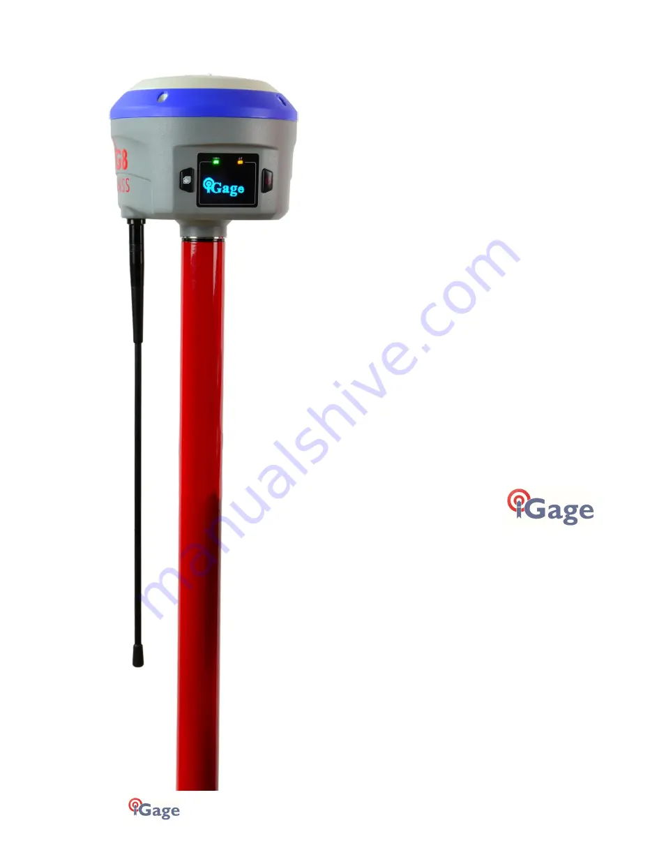
iG8
GNSS RTK Receiver
with Internal Satel 1-Watt Radio
User Manual
This manual is for use with iG8 RTK GNSS receivers produced by iGage Mapping
Corporation.
Receivers purchased from other sources that appear to be similar will not
match devices provisioned by iGage.
The ‘iGx Download Tool’ supplied with iG receivers and available for download
via the internet, only works with receivers purchased from iGage. This tool is
not sold separately.
23 January 2020
iG8_UserManual_RevJ_215.docx


