


SAILORPC-12A Panel PC
Page i
IEI Technology Corp.
User Manual
MODEL:
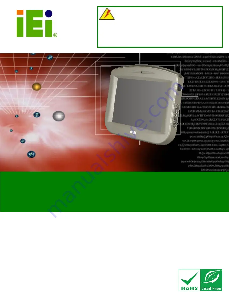
SAILORPC-12A
WARNING
Tighten air pressure release screw to 7 kg-cm prior to use. This
screw is loosened prior to shipping. System is not waterproof until
this screw is tightened. Refer to diagram on page 14 for details.
Waterproof Panel PC 1.6GHz Intel® Atom CPU
802.11b/g/n Wireless, Gigabit Ethernet, USB, RS-232
RS-232/422/485, CAN Bus, RoHS Compliant, IP 67
Rev. 1.12 – 25 September, 2009
Summary of Contents for SAILORPC-12A
Page 10: ......
Page 11: ...SAILORPC 12A Panel PC Page 1 Chapter 1 1 Introduction ...
Page 17: ...SAILORPC 12A Panel PC Page 7 1 7 Dimensions Figure 1 5 Dimensions units in mm ...
Page 18: ...SAILORPC 12A Panel PC Page 8 Chapter 2 2 Unpacking ...
Page 23: ...SAILORPC 12A Panel PC Page 13 Chapter 3 3 Installation ...
Page 39: ...SAILORPC 12A Panel PC Page 29 Chapter 4 4 OSD ...
Page 42: ...SAILORPC 12A Panel PC Page 32 Chapter 5 5 BIOS Setup ...
Page 86: ...SAILORPC 12A Panel PC Page 76 Chapter 6 6 System Maintenance ...
Page 92: ...SAILORPC 12A Panel PC Page 82 Appendix A A Safety Precautions ...
Page 96: ...SAILORPC 12A Panel PC Page 86 Appendix B B BIOS Options ...
Page 100: ...SAILORPC 12A Panel PC Page 90 Appendix C C Terminology ...
Page 104: ...SAILORPC 12A Panel PC Page 94 Appendix D D Watchdog Timer ...
Page 107: ...SAILORPC 12A Panel PC Page 97 Appendix E E Hazardous Materials Disclosure ...


