background image


PPC2-Cxxx-EHL Series Panel PC 

Page  i 

User Manual 

  PC


Rev. 1.00 

 November 10, 2022 


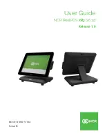
Panel PC equips Intel® Celeron® J6412 processor, on-board 

8GB memory, HDMI display output, dual 2.5G Ethernet port, 

one M.2 M key & one M.2 B key expansion slots, 12~24V DC 

input, anti-glare and anti-UV 10-point touchscreen  


PPC2-Cxxx-EHL Series 
B/15B/17B/19B-BTi 

MODEL: 
 

Summary of Contents for PPC2-C-EHL Series

Page 1: ...r 10 2022 Panel PC equips Intel Celeron J6412 processor on board 8GB memory HDMI displayoutput dual 2 5G Ethernet port one M 2 M key one M 2 B key expansion slots 12 24V DC input anti glare and anti U...

Page 2: ...PPC2 Cxxx EHL Series Panel PC Page ii Revision Date Version Changes November 10 2022 1 00 Initial release...

Page 3: ...verheating do not operate it in an area that exceeds the maximum operating temperature described in the user manual Vorsicht Um eine berhitzung des Systems zu vermeiden betreiben Sie es ausschlie lich...

Page 4: ...uso di un altro tipo di adattatore pu causare rischio d incendio o esplosione Si prega di fare riferimento al manuale utente per le specifiche sull alimentazione Atenci n Utilice solamente el adaptad...

Page 5: ...ges arising out of the use or inability to use the product or documentation even if advised of the possibility of such damages This document contains proprietary information protected by copyright All...

Page 6: ...UTION Cautionary messages should be heeded to help reduce the chance of losing data or damaging the product NOTE These messages inform the reader of essential but non critical information These messag...

Page 7: ...15 EHL Dimensions 10 1 7 5 PPC2 CW15 EHL Dimensions 11 1 7 6 PPC2 C17 EHL Dimensions 12 1 7 7 PPC2 C19 EHL Dimensions 13 1 7 8 PPC2 CW19 EHL Dimensions 14 1 7 9 PPC2 CW22 EHL Dimensions 15 1 8 SPECIFI...

Page 8: ...1 3 14 1 Driver Download 52 4 SYSTEM MAINTENANCE 54 4 1 SYSTEM MAINTENANCE INTRODUCTION 55 4 2 MOTHERBOARD REPLACEMENT 55 5 INTERFACE CONNECTORS 56 5 1 PERIPHERAL INTERFACE CONNECTORS 57 5 2 INTERNAL...

Page 9: ...3 1 HDMI Connector HDMI1 67 5 3 2 2 5GbE Connector LAN1 LAN2 68 5 3 3 USB 2 0 Connectors USB2_CON1 68 5 3 4 USB 3 2 Gen 1 Connector USB3_CON1 68 A REGULATORY COMPLIANCE 70 B SAFETY PRECAUTIONS 75 B 1...

Page 10: ...m 12 Figure 1 14 PPC2 C19 EHL Dimensions mm 13 Figure 1 15 PPC2 CW19 EHL Dimensions mm 14 Figure 1 16 PPC2 CW22 EHL Dimensions mm 15 Figure 3 1 PPC2 Cxxx EHL Back Cover Retention Screws 28 Figure 3 2...

Page 11: ...Mount Kit 43 Figure 3 25 Tighten the Mounting Screws 43 Figure 3 26 Install into a Rack Cabinet 44 Figure 3 27 Arm Mounting Retention Screw Holes 45 Figure 3 28 Arm Mounting ARM XX RS 46 Figure 3 29...

Page 12: ...Table 5 6 Capacitive touch port TOUCH_USB Pinouts 60 Table 5 7 SATA 6Gb s connectors SATA2 Pinouts 60 Table 5 8 SATA power connectors SATA2_PWR Pinouts 60 Table 5 9 Resistive touch port DMC6000_CN1 P...

Page 13: ...PPC2 Cxxx EHL Series Panel PC Page xiii Table 5 23 USB 3 2 Gen 1 Connector USB3_CON1 69...

Page 14: ......

Page 15: ...PPC2 Cxxx EHL Series Panel PC Page 1 1 Introduction Chapter 1...

Page 16: ...lied in harsh industrial environments and enriches aesthetic experience at the same time The Intel Celeron processor J6412 is a SoC System on Chip that ensures optimal memory graphics and peripheral I...

Page 17: ...W15 EHL J1 8G R10 15 6 PPC2 C17 EHL J1 8G R10 17 PPC2 C19 EHL J1 8G R10 19 PPC2 CW19 EHL J1 8G R10 18 5 PPC2 CW22 EHL J1 8G R10 21 5 Table 1 1 Model Variation 1 3 Features Some of the features of the...

Page 18: ...ure 1 2 is a flat panel LCD touchscreen surrounded by an aluminum frame Figure 1 2 Front View 1 5 Rear Panel The rear panel has a fan vent four VESA 75 100 mounting holes and several retention screws...

Page 19: ...Cxxx EHL Series Panel PC Page 5 1 6 Bottom Panel The bottom panel has the following interfaces Figure 1 4 PPC2 C08 EHL Bottom View Figure 1 5 PPC2 C10 EHL Bottom View Figure 1 6 PPC2 C12 EHL Bottom V...

Page 20: ...C15 CW15 C17 C19 CW19 CW22 EHL Bottom View WARNING Before installing the operating system the user must enter the Boot BIOS menu first and choose which operating system will be installed Otherwise the...

Page 21: ...PPC2 Cxxx EHL Series Panel PC Page 7 1 7 Dimensions 1 7 1 PPC2 C08 EHL Dimensions Figure 1 8 PPC2 C08 EHL Dimensions Unit mm...

Page 22: ...PPC2 Cxxx EHL Series Panel PC Page 8 1 7 2 PPC2 C10 EHL Dimensions Figure 1 9 PPC2 C10 EHL Dimensions mm...

Page 23: ...PPC2 Cxxx EHL Series Panel PC Page 9 1 7 3 PPC2 C12 EHL Dimensions Figure 1 10 PPC2 C12 EHL Dimensions mm...

Page 24: ...PPC2 Cxxx EHL Series Panel PC Page 10 1 7 4 PPC2 C15 EHL Dimensions Figure 1 11 PPC2 C15 EHL Dimensions mm...

Page 25: ...PPC2 Cxxx EHL Series Panel PC Page 11 1 7 5 PPC2 CW15 EHL Dimensions Figure 1 12 PPC2 CW15 EHL Dimensions mm...

Page 26: ...PPC2 Cxxx EHL Series Panel PC Page 12 1 7 6 PPC2 C17 EHL Dimensions Figure 1 13 PPC2 C17 EHL Dimensions mm...

Page 27: ...PPC2 Cxxx EHL Series Panel PC Page 13 1 7 7 PPC2 C19 EHL Dimensions Figure 1 14 PPC2 C19 EHL Dimensions mm...

Page 28: ...PPC2 Cxxx EHL Series Panel PC Page 14 1 7 8 PPC2 CW19 EHL Dimensions Figure 1 15 PPC2 CW19 EHL Dimensions mm...

Page 29: ...PPC2 Cxxx EHL Series Panel PC Page 15 1 7 9 PPC2 CW22 EHL Dimensions Figure 1 16 PPC2 CW22 EHL Dimensions mm...

Page 30: ...Hz TDP 10W Memory 8GB dual channel on board LPDDR4x Touchscreen Multi point projected capacitive type anti UV anti glare coating support gloves Surface hardness 7H Touch Controller Projected capacitiv...

Page 31: ...10Gb s 2 x USB 2 0 1 x RS 232 422 485 1 x RS 232 1 x 12V 24V power jack 1 x Power terminal block 2 pin 1 x AT ATX switch 1 x Power button 1 x Reset button 1 x Clear CMOS button PPC2 XIO 03 R10 1 x RS...

Page 32: ...type EETI 80 Drive Bay 1 x 2 5 HDD SSD drive bay Ethernet 2 x 2 5GbE LAN via Intel I225 V Expansion 1 x M 2 2242 2280 B key PCIe Gen3 x1 USB 3 0 1 x M 2 2242 M key PCIe Gen3 x2 Mounting Panel Wall Ra...

Page 33: ...Specifications PPC2 C19 PPC2 CW19 PPC2 CW22 LCD Display 19 5 4 18 5 16 9 21 5 16 9 Max Resolution 1280 W x 1024 H 1920 W x 1080 H 1920 W x 1080 H Brightness 350cd m 400cd m 400cd m Contrast Ratio 1000...

Page 34: ...DC Power Adapter 60W power adapter Thermal Solution Fanless TPM Intel Platform Trust Technology Watchdog Timer Software Programmable support 1 255 sec system reset Operating Temperature With air flow...

Page 35: ...s Panel PC Page 21 PPC2 C19 PPC2 CW19 PPC2 CW22 1 x Reset button 1 x Clear CMOS button PPC2 XIO 01 R10 2 x USB 2 0 2 x RS 232 DB9 1 x M 2 B key 2242 2280 PCIe Gen3 x 2 USB 2 0 Table 1 4 PPC2 C19 CW19...

Page 36: ...PPC2 Cxxx EHL Series Panel PC Page 22 2 Unpacking Chapter 2...

Page 37: ...the installation process Step 1 Use box cutters a knife or a sharp pair of scissors that seals the top side of the external second box Step 2 Open the external second box Step 3 Use box cutters a knif...

Page 38: ...l mount kit pack Table 2 1 Packing List If any of the above items are missing or damaged contact the distributor or sales representative immediately 2 3 OptionalItems The following items are optional...

Page 39: ...PPC2 Cxxx EHL Series Panel PC Page 25 3 Installation Chapter 3...

Page 40: ...n anti static wristband Wearing a simple anti static wristband can help to prevent ESD from damaging the board Self grounding Before handling the board touch any grounded conducting material During th...

Page 41: ...at at least two people are assisting with the procedure Anti static Discharge If a user open the rear panel of the panel PC to configure the jumpers or plug in added peripheral devices ground themselv...

Page 42: ...gure the system 3 5 Removing the Back Cover Remove the back cover retention screws on the back cover Lift the cover up to remove NOTE The number of retention screws on the chassis varies by models Fig...

Page 43: ...e HDD bracket from the PPC2 Cxxx EHL Series The HDD bracket is secured on the panel PC with four retention screws Figure 3 2 Remove the four retention screws and disconnect the SATA and SATA power cab...

Page 44: ...30 Figure 3 3 HDD Retention Screws Step 4 Reinstall the HDD bracket into the PPC2 Cxxx EHL Series and fasten the four hard drive bracket screws Figure 3 4 Connect the SATA and SATA power cables Figure...

Page 45: ...ot allows installation of M 2 2280 cards To install an M 2 card please follow the steps below Step 1 Remove the back cover See Section 557H3 5 Step 2 Locate the M 2 slot as shown in Figure 3 5 Figure...

Page 46: ...e end of the M 2 retaining clip Step 4 Insert M 2 card The notch at the end of the M 2 card needs to be aligned with the notch of the fixed buckle Figure 3 7 Figure 3 7 Insert M 2 Card Step 5 Secure t...

Page 47: ...gh an AT ATX switch on the I O interface panel The system is set to ATX mode by default The switch is shown below Figure 3 9 AT ATX Mode Selection AT ATX Switch AT ATX Default Power Switch Position Of...

Page 48: ...are described in the following sections 3 9 1 Wall Mounting To mount the PPC2 Cxxx EHL Series panel PC onto a wall please follow the steps below Step 1 Select the location on the wall for the wall mou...

Page 49: ...d against the rear panel Figure 3 11 Step 7 Align the mounting screws on the monitor rear panel with the mounting holes on the bracket Step 8 Carefully insert the screws through the holes and gently p...

Page 50: ...the wall mounting kit on the top panel of the panel PC Carefully mark the location of the wall mounting kit screw holes on the wall Drill a pilot hole at the marked location on the wall Secure the wa...

Page 51: ...PPC2 Cxxx EHL Series Panel PC Page 37 Figure 3 12 Secure the Chassis...

Page 52: ...el PC all mounting kit must be installed Figure 3 13 Figure 3 13 PPC2 Cxxx EHL Series Panel Mount Kit Installation Step 1 Select the position on the panel to mount the PPC2 Cxxx EHL Series Step 2 Cut...

Page 53: ...PPC2 Cxxx EHL Series Panel PC Page 39 Figure 3 14 PPC2 C08 EHL Panel Cutout Dimensions Figure 3 15 PPC2 C10 EHL Panel Cutout Dimensions...

Page 54: ...PPC2 Cxxx EHL Series Panel PC Page 40 Figure 3 16 PPC2 C12 EHL Panel Cutout Dimensions Figure 3 17 PPC2 C15 EHL Panel Cutout Dimensions Figure 3 18 PPC2 C17 EHL Panel Cutout Dimensions...

Page 55: ...PPC2 Cxxx EHL Series Panel PC Page 41 Figure 3 19 PPC2 C19 EHL Panel Cutout Dimensions Figure 3 20 PPC2 CW15 EHL Panel Cutout Dimensions Figure 3 21 PPC2 CW19 EHL Panel Cutout Dimensions...

Page 56: ...xx EHL Series through the hole until the aluminum frame is flush against the panel Figure 3 23 Figure 3 23 Machine mounted to panel Step 4 Insert the panel mount kit into the prefabricated holes along...

Page 57: ...e screws that pass through the mounting clamps until the plastic caps at the front of all the screws are firmly secured to the panel Figure 3 25 Figure 3 25 Tighten the Mounting Screws Step 6 Slide th...

Page 58: ...Association compliant and can be mounted on an arm with a 75 100 mm interface pad To mount the PPC2 Cxxx EHL Series on an arm please follow the steps below Step 1 The arm is a separately purchased ite...

Page 59: ...ew holes on the mounting arm interface with those in the PPC2 Cxxx EHL Series panel PC The arm mounting retention screw holes of the PPC2 Cxxx EHL Series panel PC are shown in Figure 3 27 Figure 3 27...

Page 60: ...Arm Mounting ARM XX RS 3 9 4 Stand Mounting To mount the PPC2 Cxxx EHL Series using the stand mounting kit please follow the steps below Step 1 Locate the screw holes on the rear of the PPC2 Cxxx EHL...

Page 61: ...ket to the PPC2 Cxxx EHL Series insert the retention screws into the screw holes and tighten them S t e p 0 Figure 3 30 Stand Mounting Stand Cxx 3 10 Serial Device Connection The PPC2 Cxxx EHL Series...

Page 62: ...ns of PPC2 C15 CW15 C17 C19 CW19 CW22 EHL 3 10 1 RS 232 Serial Ports The pinouts of the RS 232 serial ports are listed in the following table PIN NO DESCRIPTION PIN NO DESCRIPTION 1 DCD 2 RXD 3 TXD 4...

Page 63: ...erial Port COM3 Pinouts 3 11 Powering On the System To power on the system follow the steps below Step 1 Either connect the power adapter to the power jack or connect the power cable to the 2 pin powe...

Page 64: ...3 34 Press the reset button to reboot the system Figure 3 34 Reset Button Location 3 13 Clear CMOS If the PPC2 Cxxx EHL Series fails to boot due to improper BIOS settings the clear CMOS button clears...

Page 65: ...ce Download Center https download ieiworld com Type PPC2 Cxxx EHL Series and press Enter to find all the relevant software utilities and documentation Figure 3 36 IEI Resource Download Center The foll...

Page 66: ...PPC2 Cxxx EHL Series and press Enter Step 2 All product related software utilities and documentation will be listed You can choose Driver to filter the result Step 3 Click the driver file name on the...

Page 67: ...PPC2 Cxxx EHL Series Panel PC Page 53 NOTE To install software from the downloaded ISO image file in Windows 10 or 11 double click the ISO file to mount it as a virtual drive to view its content...

Page 68: ...PPC2 Cxxx EHL Series Panel PC Page 54 Chapter 4 4 System Maintenance...

Page 69: ...ed Please contact the system reseller or vendor to purchase replacement parts Replacement instructions for the above listed components are described below 4 2 Motherboard Replacement A user cannot rep...

Page 70: ...PPC2 Cxxx EHL Series Panel PC Page 56 5 Interface Connectors Chapter 5...

Page 71: ...e connectors and configuration jumpers The connector locations are shown in Figure 5 1 and Figure 5 2 The Pin 1 locations of the on board connectors are also indicated in the diagrams The connector pi...

Page 72: ...wafer EC_DEBUG1 SPI flash connector 6 pin wafer JBIOS1 Capacitive touch port 4 pin wafer TOUCH_USB SATA III connectors 7 pin connector SATA2 SATA power connectors 2 pin wafer SATA2_PWR Resistive touch...

Page 73: ...nector BAT2 Pinouts 5 2 3 EC debug port EC_DEBUG1 PIN NO DESCRIPTION PIN NO DESCRIPTION 1 NC 2 EDICS 3 EDIDO 4 EDICLK 5 EDIDI 6 GND Table 5 4 EC debug port EC_DEBUG1 5 2 4 SPI flash connector JBIOS1 P...

Page 74: ...Gb s connectors SATA2 Pinouts 5 2 7 SATA power connectors SATA2_PWR PIN NO DESCRIPTION 1 5V 2 GND Table 5 8 SATA power connectors SATA2_PWR Pinouts 5 2 8 Resistive touch port DMC6000_CN1 PIN NO DESCRI...

Page 75: ...2_1 PIN NO DESCRIPTION PIN NO DESCRIPTION 1 NC 2 3 3V 3 GND 4 3 3V 5 GND 6 NC 7 USB_D 8 NC 9 USB_D 10 NC 11 GND 12 Module Key 13 Module Key 14 Module Key 15 Module Key 16 Module Key 17 Module Key 18 M...

Page 76: ...56 NC 57 GND 58 NC 59 NC 60 NC 61 NC 62 NC 63 NC 64 NC 65 NC 66 SUSCLK 67 GND 68 TP5 69 GND 70 3 3V 71 GND 72 3 3V 73 GND 74 3 3V 75 GND Table 5 11 M 2 B Key slot M2_1 Pinouts 5 2 11 M 2 M Key slot M2...

Page 77: ...PCIE_RXP4 44 NC 45 GND 46 NC 47 PCIE_TXN4 48 NC 49 PCIE_TXP4 50 PERST 51 GND 52 TP6 53 CLKN 54 PCIE_WAKE 55 CLKP 56 TP4 57 GND 58 TP3 59 Module Key 60 Module Key 61 Module Key 62 Module Key 63 Module...

Page 78: ...22 V3 3S 23 Display Detect PIN 24 V3 3S 25 GND 26 V3 3S 27 GND 28 GND 29 EDP_TX3_DN 30 V12S 31 EDP_TX3_DP 32 V12S 33 GND 34 V12S 35 EDP_TX2_DN 36 V12S 37 EDP_TX2_DP 38 GND 39 GND 40 CLK 41 EDP_TX1_DN...

Page 79: ...PPC2 Cxxx EHL Series Panel PC Page 65 67 GND 68 V12A 69 GND 70 V12A 71 GND 72 V12A 73 GND 74 V12A 75 GND Table 5 13 IDPM connector J_M2_EDP_LVDS Pinouts...

Page 80: ...DESCRIPTION PIN NO DESCRIPTION 1 CS_EC 2 3 3V 3 SO_EC 4 HOLD_EC 5 EC_DET_FLASH 6 SCK_EC 7 GND 8 SIO_EC Table 5 15 SPI flash EC connector EC_SPI1 Pinouts 5 2 15 Chassis intrusion CHASSIS1 PIN NO DESCR...

Page 81: ...ype Label ATX AT mode switch Switch J_ATX_AT1 Clear CMOS button Push button J_CMOS1 Reset button Push button RST_BTN1 RS 232 422 485 serial ports DB 9 COM1 RS 232 serial port DB 9 COM2 HDMI connector...

Page 82: ...2 MDIA0 6 MDIA1 3 MDIA1 7 MDIA3 4 MDIA2 8 MDIA3 Table 5 21 2 5GbE Connector LAN1 LAN2 Pinouts 5 3 3 USB 2 0 Connectors USB2_CON1 PIN NO DESCRIPTION PIN NO DESCRIPTION 1 USB_VCC 5 USB_VCC 2 DATA 6 DATA...

Page 83: ...PPC2 Cxxx EHL Series Panel PC Page 69 7 GND 16 GND 8 USB3_TX 17 USB3_TX 9 USB3_TX 18 USB3_TX Table 5 23 USB 3 2 Gen 1 Connector USB3_CON1 Pinouts...

Page 84: ...PPC2 Cxxx EHL Series Panel PC Page 70 Appendix A A Regulatory Compliance...

Page 85: ...compliance with the essential requirements and other relevant provisions of Directive 2014 53 EU Bulgarian IEI Integration Corp 2014 53 EU esky Czech IEI Integration Corp t mto prohla uje e tento za z...

Page 86: ...53 EU Lietuvi Lithuanian IEI Integration Corp deklaruoja kad is ranga atitinka esminius reikalavimus ir kitas 2014 53 EU Direktyvos nuostatas Nederlands Dutch IEI Integration Corp dat het toestel toes...

Page 87: ...lo ili direktive 2014 53 EU Slovensky Slovak IEI Integration Corp t mto vyhlasuje e zariadenia sp a z kladn po iadavky a v etky pr slu n ustanovenia Smernice 2014 53 EU Suomi Finnish IEI Integration C...

Page 88: ...interference at his own expense Federal Communication Commission Interference Statement This equipment has been assembled with components that comply with the limits for a Class B digital device pursu...

Page 89: ...PPC2 Cxxx EHL Series Panel PC Page 75 B Safety Precautions Appendix B...

Page 90: ...revent the risk of electric shock make sure power cord is unplugged from wall socket To fully disengage the power to the unit please disconnect the power cord from the AC outlet Refer servicing to qua...

Page 91: ...nents including the PPC2 Cxxx EHL Series Dry climates are especially susceptible to ESD It is therefore critical that whenever the PPC2 Cxxx EHL Series is opened and any of the electrical components a...

Page 92: ...le is classified as electronic device in terms of the European Directive 2012 19 EU WEEE and must not be disposed of as domestic garbage EU wide legislation as implemented in each Member State require...

Page 93: ...ever spray or squirt liquids directly onto any other components To clean the LCD panel gently wipe it with a piece of soft dry cloth or a slightly moistened cloth The interior of the device does not r...

Page 94: ...is not recommended when cleaning the device as they may damage the plastic parts Vacuum cleaner Using a vacuum specifically designed for computers is one of the best methods of cleaning the device Dus...

Page 95: ...PPC2 Cxxx EHL Series Panel PC Page 81 C Watchdog Timer Appendix C...

Page 96: ...A BIOS function call INT 15H is used to control the Watchdog Timer INT 15H AH 6FH Sub function AL 2 Sets the Watchdog Timer s period BL Time out value Its unit second is dependent on the item Watchdog...

Page 97: ...the system resets Example program INITIAL TIMER PERIOD COUNTER W_LOOP MOV AX 6F02H setting the time out value MOV BX 05 time out value is 5 seconds INT 15H ADD THE APPLICATION PROGRAM HERE CMP EXIT_AP...

Page 98: ...PPC2 Cxxx EHL Series Panel PC Page 84 Appendix D D Hazardous Materials Disclosure...

Page 99: ...lamps These components will be separately marked Please refer to the following table Part Name Toxic or Hazardous Substances and Elements Lead Pb Mercury Hg Cadmium Cd Hexavalent Chromium CR VI Polyb...

Page 100: ...es Panel PC Page 86 RoHS RoHS Pb Hg Cd CR VI PBB PBDE O O O O O O O O O O O O O O O O O O O O O O O O O O O O O O O O O O O O O O O O O O O O O O O O O SJ T 11363 2006 GB T 26572 2011 X SJ T 11363 200...

Reviews: