ICEROCK-08A Panel PC
Page i
IEI Technology Corp.
User Manual
MODEL:
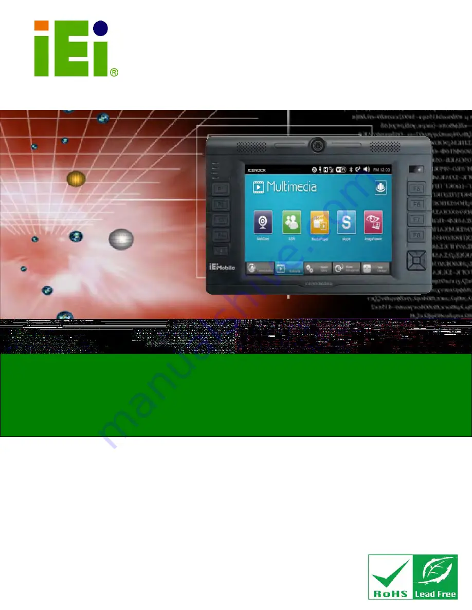
ICEROCK-08A
Industrial Tablet PC 1.6 GHz Intel® Atom™ Z530P CPU
On-board 1 GB DDR2 SDRAM, 802.11b/g/n Wireless, Mobile
3.75G, Gigabit Ethernet, USB, Mini USB, SD and CF card slots,
RoHS Compliant, IP62 Compliant Front Panel
Rev. 1.13 – 8 July, 2010
Summary of Contents for ICEROCK-08A Series
Page 2: ...ICEROCK 08A Panel PC Page ii Revision Date Version Changes 8 July 2010 1 00 Initial release ...
Page 12: ...ICEROCK 08A Panel PC Page 1 Chapter 1 1 Introduction ...
Page 21: ...ICEROCK 08A Panel PC Page 10 1 9 Dimensions Figure 1 7 Dimensions units in mm ...
Page 22: ...ICEROCK 08A Panel PC Page 11 Chapter 2 2 Unpacking ...
Page 26: ...ICEROCK 08A Panel PC Page 15 Chapter 3 3 Installation ...
Page 40: ...ICEROCK 08A Panel PC Page 29 Chapter 4 4 Demo Application ...
Page 48: ...ICEROCK 08A Panel PC Page 37 Figure 4 11 Audio Brightness Setting ...
Page 51: ...ICEROCK 08A Panel PC Page 40 Chapter 5 5 BIOS Setup ...
Page 83: ...ICEROCK 08A Panel PC Page 72 Chapter 6 6 System Maintenance ...
Page 85: ...ICEROCK 08A Panel PC Page 74 Appendix A A Safety Precautions ...
Page 89: ...ICEROCK 08A Panel PC Page 78 Appendix B B One Key Recovery ...
Page 95: ...ICEROCK 08A Panel PC Page 84 Figure B 3 Partition Creation Commands ...
Page 115: ...ICEROCK 08A Panel PC Page 104 Appendix C C BIOS Options ...
Page 118: ...ICEROCK 08A Panel PC Page 107 Appendix D D Terminology ...
Page 122: ...ICEROCK 08A Panel PC Page 111 Appendix E E Watchdog Timer ...
Page 125: ...ICEROCK 08A Panel PC Page 114 Appendix F F Hazardous Materials Disclosure ...