


ECN-360A-D2550 Em b e d d e d S ys te m
P a g e i
IEI Te c h n o lo g y Co rp .
Us e r Ma n u a l
,
MODEL:
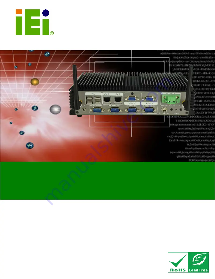
ECN-360A-D2550
Em b e d d e d S ys te m with In te l® d u a l c o re Ato m ™ D2550 P ro c e s s o r,
Two VGA, S ix US B 2.0, Fo u r COM,
Gb E a n d Ro HS Co m p lia n t
Re v. 1.00 – 1 J u ly 2013
Summary of Contents for ECN-360A-D2550
Page 12: ...ECN 360A D2550 Embedded Sys tem Page 1 Chapter 1 1 Introduction...
Page 17: ...ECN 360A D2550 Embedded Sys tem Page 6 Figure 1 3 ECN 360A D2550 Rear Panel...
Page 19: ...ECN 360A D2550 Embedded Sys tem Page 8 Chapter 2 2 Unpacking...
Page 23: ...ECN 360A D2550 Embedded Sys tem Page 12 Chapter 3 3 Ins tallation...
Page 34: ...ECN 360A D2550 Embedded Sys tem Page 23 Chapter 4 4 Sys tem Motherboard...
Page 58: ...ECN 360A D2550 Embedded Sys tem Page 47 Chapter 5 5 BIOS...
Page 86: ...ECN 360A D2550 Embedded Sys tem Page 75 A Safety Precautions Appendix A...
Page 91: ...ECN 360A D2550 Embedded Sys tem Page 80 B BIOS Menu Options Appendix B...
Page 94: ...ECN 360A D2550 Embedded Sys tem Page 83 Appendix C C One Key Recovery...
Page 102: ...ECN 360A D2550 Embedded Sys tem Page 91 Figure C 5 Partition Creation Commands...
Page 135: ...ECN 360A D2550 Embedded Sys tem Page 124 D Watchdog Timer Appendix D...
Page 138: ...ECN 360A D2550 Embedded Sys tem Page 127 Appendix E E Hazardous Materials Dis clos ure...


