IDT 89HPEB383, User Manual
The IDT 89HPEB383 User Manual is available for free download. This comprehensive manual provides detailed instructions and information about operating and maintaining the product. Easily access and download this manual from our website, ensuring you have all the information you need for an optimal user experience.
Share
Download


Reviews:
No comments
Related manuals for 89HPEB383

T1
Brand: Xilinx Pages: 48

NVITE
Brand: Nedap Pages: 40

MSR206
Brand: Unitech Pages: 2

H-GA32T
Brand: Hawking Pages: 2
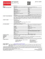
SKU 4670PE31GDT
Brand: Diamond Multimedia Pages: 1

MPG401
Brand: CTI Pages: 22

PRX-TSEC-STD-B
Brand: ICT Pages: 38

SkyLINE 11Mb
Brand: Farallon Pages: 40

855-S1610040400
Brand: ddm hopt+schuler Pages: 25

iCLASS SE
Brand: HID Pages: 2

PISO-CAN-FD Series
Brand: ICP DAS USA Pages: 88

DA-70824
Brand: Digitus Pages: 4

PIC-H61
Brand: DFI Pages: 60

Conekt CSR-35L
Brand: Farpointe Data Pages: 2
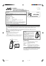
KS-USB10
Brand: JVC Pages: 2

MRW62ES1181 - Card Reader USB
Brand: Sony Pages: 2

MRW66E-H1
Brand: Sony Pages: 2

MRW620-U1
Brand: Sony Pages: 2


